Immunological Synapse Formation Between Helper T Cells and Antigen-Presenting Cells
Abstract
Source: Bello-Gamboa, A. et al., Imaging the Human Immunological Synapse. J. Vis. Exp. (2019)
This video demonstrates the in vitro study of immunological synapse formation between an antigen-presenting cell and helper T lymphocytes using a fluorescence microscope. T cell receptors of helper T lymphocytes interact with an antigen-MHC-II complex in antigen-presenting cells and form immunological synapses, followed by secretory vesicle movements toward the synapse, which is visualized by fluorescent microscopy.
Protocol
1. Preparation of Slides to Adhere Raji Cells
- Add 150 µL of fibronectin (100 µg/mL) per well to an 8 microwell chamber slide (plastic-bottom chamber slide) and incubate it for 30 min to 1 h at 37 °C. This adhesion substrate will allow the binding of Raji cells to the well bottom (Step 2), the formation of living conjugates with Jurkat cells (Step 4) cells, and time-lapse microscopy capture (step 6), and is also compatible afterward with optional paraformaldehyde (PFA) fixation.
NOTE: For acetone fixation, use glass bottom chamber slides and poly-L-lysine (20 µg/mL) instead of fibronectin, since acetone dissolves plastic. The 8 microwell chamber slide (1 cm2 well, 300 µL maximum volume) or equivalent is a flexible and appropriate format. - Aspirate fibronectin using a 200 μL automatic pipette and wash each well with 200 µL of PBS for 2 min with gentle shaking. Repeat this wash one more time. The chamber slide can be stored at this stage with PBS for 1-2 weeks at 4 °C.
2. Adhesion of Raji Cells to the Chamber Slides and 7-amino-4-chloromethylcoumarin (CMAC) Labeling
- Transfer 10 mL of a confluent (1-2 x 10⁶ cells/mL) pre-culture of Raji cells to a 15 mL, V-bottom tube. Mix well and use 10 µL to count the cells on the Neubauer chamber or equivalent.
- Centrifuge the remaining cells at 300 x g for 5 min at room temperature. Aspirate and discard the supernatant.
- Gently resuspend the cell pellet in a warm complete culture medium (RPMI 1640 supplemented with 10% FCS, 2 mM glutamine, 10 mM HEPES, 100 U/mL penicillin, and 100 µg/mL streptomycin) at a concentration of 106 cells/mL. Use the equation given below:
([ ]initial x Vinitial = [ ]final x Vfinal), where [ ]initial represents initial cell concentration, Vinitial = initial volume of the cell suspension, [ ]final = final cell concentration, Vfinal = final volume of the cell suspension.
NOTE: Depending on the cell concentration of the starting culture, it is possible to collect more cells than needed but it is important to maintain the remaining cells in culture (37 °C) till the end of the experiment in order to prevent potential problems (see Step 2.6). - Label Raji cells to allow for their identification during the synaptic conjugate formation. In this experiment, 7-amino-4-chloromethylcoumarin (CMAC) labeling is performed in step 2.4.2.
- Transfer the required number of Raji cells in the culture medium to a 2 mL tube. For the 8 microwell chamber slides, a total of 1.6 mL of the cell suspension is needed (200 µL per well).
- Add CMAC to a final concentration of 10 µM. Keep the cells in the dark by covering the tube with aluminum foil since CMAC is light-sensitive. 200 µL containing 2 x 10⁵ Raji cells are needed per 1 cm2 well. Thus, if 8 wells need to be prepared, 1.6 x 10⁶ Raji cells are required.
NOTE: Labeling Raji cells with cell tracker blue (CMAC, UV excitation, and blue emission) distinguishes them from Th cells when the synaptic conjugates are formed. This dye is compatible with PFA and acetone fixatives and allows further immunofluorescence procedures. Try to avoid light exposition. The labeling of Raji cells in a pool with CMAC followed by resuspension before the adhesion of the Raji cells to the fibronectin-coated chamber slides ensures the homogeneous labeling of Raji cells with CMAC among different wells.
- Resuspend CMAC-stained cells and, after aspiration of the PBS in the chamber slide from step 1.2., transfer 200 µL of the cell suspension to each well of the fibronectin-coated chamber slides prepared in steps 1.1-1.2. Incubate the chamber slide at 37 °C, 5% CO2 for 30 min-1 h.
NOTE: The adhesion and CMAC labeling will simultaneously occur at this step and this saves time. Please be aware that Raji cells will sediment quickly and caution needs to be taken to maintain a homogeneous concentration in the cell suspension before seeding. It is not necessary to wash CMAC at this stage by centrifugation since CMAC washing will be more easily done at step 2.7 (when the labeled Raji cells have already adhered to the chamber slides). Since CMAC is present in the cell suspension in large excess, the blue fluorescence background is too high to distinguish the blue-stained cells. Check cell CMAC fluorescence in step 2.7 after CMAC washing. - Ensure that Raji cells are adhered to the bottom of the wells by gentle shaking of the chamber slides on the microscope. Ensure that the cells display gaps among each other and are not confluent (Figure 1, middle panel). 50-60% of cell confluence is appropriate.
- If most of the cells efficiently adhere to the chamber slide and no cell gaps are observed, wash each well with a warm complete medium and resuspend the medium with a 200 μL automatic pipet to detach cell excess. Check confluence after each resuspension step.
- If the cells do not adhere, repeat the adhesion step again and increase adhesion time and/or cell number.
NOTE: It is possible to stop here, incubate the chamber slide at 37 °C, 5% CO2 overnight (O/N), and continue with the protocol the next day. Please confirm the next day that Raji cells remain adhered and CMAC-labeled by using fluorescence microscopy.
- Wash each well again carefully with warm supplemented RPMI to eliminate excess CMAC and check for blue emission with the fluorescence microscope (Figure 1).
NOTE: To avoid the use of immersion oil (sticky and viscous) and high numerical aperture oil objectives, extra-long distance (i.e., 20x or 40x) objectives can be used to quickly check CMAC labeling using the fluorescence microscope.
3. Pulse of CMAC — Labeled Raji Cells with Staphylococcal Enterotoxin E
- Add Staphylococcal Enterotoxin E (SEE, 1 µg/mL) to each well. SEE can be conveniently diluted in a cell culture medium (working solution at 100 µg/mL) from the SEE frozen stocks (1 mg/mL in PBS). Use 2 μL of the 100x working solution per 200 μL microwell.
CAUTION: Use gloves for this step and dispose of the used tip in the biohazard box. - Incubate the chamber slide at 37 °C, 5% CO2 for at least 30 min. The SEE effect lasts for at least 3-4 h.
NOTE: SEE can be added to the wells at different time points when required if distinct time-lapse setups are planned (step 5) and/or depending on the start time point for the end-point experiments (step 6).
4. Preparation of Jurkat Cells
- Use a previously growing culture of Jurkat cells (1-2 x 10⁶ cells/mL) for this experiment. Use cells from a standard culture flask or from a previous transfection following standard electroporation protocols, as previously described. The transfection of Jurkat cells will allow time-lapse visualization of the traffic of secretory granules in living cells. For instance, when GFP-CD63 (a marker of MVB) is expressed the movement of GFP-CD63-decorated vesicles can be recorded.
- Observe the cells under a phase contrast microscope. If an excess of dead cells (>20-30%) is observed, perform Ficoll density gradient centrifugation using standard protocols, to eliminate the excess of dead cells (dead cells exhibit higher density than living cells) prior to use (see Discussion).
- Transfer the cells to a 15 mL tube, V-bottom tube, and use 10 µL for counting using a hemocytometer.
- Centrifuge the remaining cells as described in step 2.2. Discard the supernatant and resuspend the cells at the same concentration as Raji cells (1 x 10⁶/mL) using a fresh, warm culture medium. Follow steps 2.2-2.3.
- Maintain the Jurkat cells in culture (37 °C, 5% CO2) while waiting for Step 4.
NOTE: In the second option (transfection), the number of living cells is going to be much lower than in the first one. Thus, consider using a higher starting cell culture volume in order to have enough cells for the experiment. From 10 x 106 Jurkat cells per electroporation cuvette and transfection, only 2-4 x 10⁶ Jurkat cells will survive after 48 h of transfection and some of these cells will be lost during the Ficoll step. Thus, one electroporation cuvette is generally sufficient to challenge the adhered SEE-pulsed Raji cells from 8 microwells (1.6 x 10⁶ transfected Jurkat cells needed).
5. Co-seeding of Raji and Jurkat Cells
- Take the chamber slides containing the CMAC-labeled, SEE-pulsed, adhered Raji cells out of the incubator from step 3.2. It is not necessary to wash the CMAC at this stage since this was previously done in Step 2.7.
- Aspirate carefully the culture medium of each well, one by one, from one corner of the well using an automatic 200 μL pipette. Do not let the medium in the well dry out completely.
- Immediately replace the medium with 200 µL of resuspended Jurkat cells in cell culture medium (1 x 10⁶/mL) prepared in step 4.5. If time-lapse imaging is performed, go to step 6 immediately after this step, since Jurkat cells tend to sediment and form synaptic conjugates very quickly. For convenience, the microwells containing SEE-pulsed, adhered Raji cells that do not receive seeding with Jurkat cells at this stage should be maintained with a cell culture medium until subsequent challenge with Jurkat cells. This will flexibly allow subsequent challenges with Jurkat cells for additional time-lapse or reverse kinetic, end-point experimental approaches.
- If a time-lapse is going to be performed, quickly proceed to step 6. This involves the co-culture for 1-2 h on the microscope stage incubator or equivalent at 37 °C, 5% CO2 to allow the synaptic conjugate formation and simultaneous image acquisition. If endpoint analysis, but no time-lapse, is foreseen check conjugate formation after the co-culture period using the microscope (as in Figure 1) before fixing the cells.
6. Time-Lapse Imaging of Emerging Synaptic Conjugates
- Prepare the microscope and incubation chamber prior to imaging. For the example, the detailed microscopy settings are shown in Figure 2.
NOTE: If a time-lapse experiment is planned, all the microscope settings and complements (ambient cell culture chamber, etc.) should be prepared before adding the Jurkat suspension to the chamber slide with adhered Raji cells. The following steps are described for a commercial microscope (Table of Materials). However, any inverted fluorescence microscope equipped with a cell culture incubator can be used.- Use a microscope with a 60x oil immersion, and high numerical aperture when imaging polarized traffic.
- Ensure that the automatic focus system is switched on and adjust the offset to focus the Raji cells bound to the bottom surface. Please refer to Figure 1.
- After Jurkat addition to each well containing the adhered Raji cells in step 5.3, quickly locate the microwell chamber slide on the pre-heated (1-2 h) microscope stage incubator (i.e., OKOlab) and select some XY positions with the microscope, fields in which it is likely to record an emerging IS formation made by, for instance, a Jurkat-transfected cell falling into the microscope focus.
- Use a pre-heated microscope stage incubator since it was observed that a temperature-stabilized stage maintains stable X, Y, Z positions. Criteria for a convenient XY field are: well-focused and non-confluent Raji cells (i.e., displaying gaps among cells) and the presence of transfected Jurkat cells (this can be checked by combining transmittance and UV or GFP channels). Jurkat cells will sediment very quickly (a few minutes) on the chamber slide, and the chances to image emerging synapses will decrease with time (Figure 1). It is possible either to finish the experiment after the defined time-lapse or proceed to Step 7 and fix the conjugates for subsequent immunofluorescence and analyses.
NOTE: It is possible to select up to 16 different microscope fields from up to 4 different microwells for simultaneous, multi-well time-lapse acquisition with the proper temporal resolution (1-2 min per frame). The limitation relies on both the number and intensity (affecting camera exposition) of the diverse fluorochromes to be imaged (dependent on the number of expressed fluorescent proteins, apart from CMAC). One way to increase the frame rate is recording for the CMAC channel in only one out of each "n" time frames for GFP (i.e., n = 8, as shown in Figure 2) since Raji cells are adhered to the well bottom and do not easily move as Jurkat cells. In addition, this benefits the cell viability, since frequent UV light exposure may damage the cells. Try to adjust the time frame rate to 1 frame every 1 minute or less (i.e., 20 s per frame, Figure 2) since the polarization of MVB takes a few min to hours to complete. A microscope equipped with a motorized epi-fluorescence turret and appropriate band-pass fluorescence filters or equivalents is necessary to perform this multichannel capture.
Representative Results
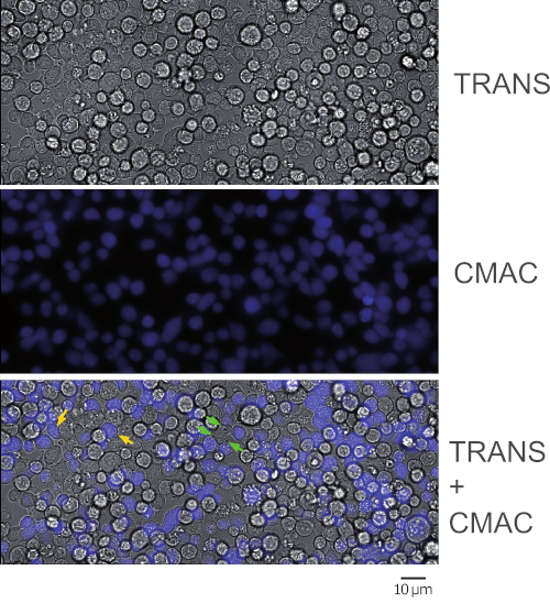
Figure 1 represents synaptic Jurkat-Raji conjugates that were obtained following the protocol (step 5.2). The image represents the first frame from a representative, time-lapse experiment. 2 x 10⁵ Raji cells and 2 x 10⁵ Jurkat cells were added to a 1 cm2 well. The upper panel shows transmittance channel, the middle panel consists of CMAC (blue) channel (Raji cells), and the lower panel shows both transmittance plus CMAC merged channels. Yellow arrows label some synaptic conjugates, as a reference, whereas green arrows indicate synaptic conjugates made by one Jurkat cell and several Raji cells (complex conjugates). Decreasing cell concentrations (105 or less cells in the 1 cm2 well) will circumvent the formation of complex cellular conjugates, but there may not be enough cell conjugates for subsequent analysis of polarized traffic (see below), that in turn will decrease also the chances to find and to image emerging synaptic conjugates.
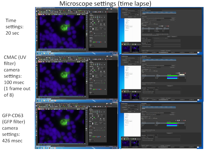
Figure 2 represents screenshots corresponding to the imaging parameters used for the simultaneous capture of the two different fluorochromes (CMAC and GFP-CD63) by using appropriate software (i.e., NIKON NIS_AR) in a representative time-lapse experiment.
Disclosures
The authors have nothing to disclose.
Materials
| Camera Nikon DS-QI1MC | Nikon | MQA11550 | Cooled Camera Head |
| CMAC | ThermoFisher Scientific | C2110 | Cell tracker blue |
| JURKAT cells | ATCC | ATCC TIB-152 | Effector T lymphocytes |
| μ-Slide 8 well ibiTreat, μ-Slide 8 well Glass-Bottom | IBIDI | Cat.No: 80826, 80827 | Cell culture and cell imaging supports |
| Microscope NIKON Eclipse Ti-E | Nikon | NIKON Eclipse Ti-E | Wide-field fluorescence, fully-motorized microscope equipped with Perfect Focus System (PFS) option |
| Microscope Stage Incubator with 3-channel manual gas mixer and gas bubbler/ humidity module | OKOLAB | H201-NIKON-TI-S-ER | Cell culture atmosphere |
| Raji Cells | ATCC | ATCC CCL-86 | APC |
| RPMI medium GIBCO | ThermoFisher Scientific | 21875034 | Culture medium |
| Streptococcus Enterotoxin E (SEE) | Toxin Technology, Inc | EP404 | Bacterial Toxin |
| Software Image J | NIH | Image J | Image software |
| Software Nikon NIS-AR | Nikon | NIS-Elements AR | Image capture and analysis software |
