The goal of the protocol is to optimize the fracture generation parameters to yield consistent fractures. This protocol accounts for the variations in bone size and morphology that may exist between animals. Additionally, a cost-effective, adjustable fracture apparatus is described.
The reliable generation of consistent stabilized fractures in animal models is essential for understanding the biology of bone regeneration and developing therapeutics and devices. However, available injury models are plagued by inconsistency resulting in wasted animals and resources and imperfect data. To address this problem of fracture heterogeneity, the purpose of the method described herein is to optimize fracture generation parameters specific to each animal and yield a consistent fracture location and pattern. This protocol accounts for variations in bone size and morphology that may exist between mouse strains and can be adapted to generate consistent fractures in other species, such as rat. Additionally, a cost-effective, adjustable fracture apparatus is described. Compared to current stabilized fracture techniques, the optimization protocol and new fracture apparatus demonstrate increased consistency in stabilized fracture patterns and locations. Using optimized parameters specific to the sample type, the described protocol increases the precision of induced traumas, minimizing the fracture heterogeneity typically observed in closed-fracture generation procedures.
Research on fracture healing is necessary to address a large clinical and economic problem. Each year over 12 million fractures are treated in the United States1, costing $80 billion per year2. The likelihood of a male or female suffering a fracture in their lifetime is 25% and 44%, respectively3. Problems associated with fracture healing are expected to increase with increased comorbidities as the population ages. To study and address this problem, robust models of fracture generation and stabilization are required. Rodent models are ideally suited for this purpose. They provide clinical relevance and can be modified to address specific conditions (i.e., multiple injuries, open, closed, ischemic, and infected fractures). In addition to replicating clinical scenarios, animal fracture models are important for understanding bone biology and developing therapeutics and devices. However, attempts to study differences between interventions may be complicated by the variability introduced by inconsistent fracture generation. Thus, generating reproducible and consistently closed fractures in animal models is essential to the field of musculoskeletal research.
Despite properly controlling for potential subject heterogeneity by ensuring the appropriate genetic background, sex, age, and environmental conditions, the production of clinically-relevant consistent bone injuries is a significant variable affecting reproducibility that must be controlled. Statistical comparisons using inconsistent fractures are plagued with experimental noise and a high variability4; in addition, fracture variability can result in unnecessary animal death because of the need to increase the sample size or the necessity to euthanize animals with comminuted or malpositioned fractures. The purpose of the method described herein is to optimize the fracture generation parameters that are specific to sample type and yield a consistent fracture location and pattern.
Current models of fracture generation fall into two broad categories, each with their own strengths and weaknesses. Open-fracture (osteotomy) models undergo surgery to expose the bone, after which a fracture is induced by cutting the bone or weakening it and then manually breaking it5,6,7,8. The benefits of this method are the direct visualization of the fracture site and a more consistent fracture location and pattern. However, the physiological and clinical relevance of the approach and mechanism of injury is limited. Additionally, open methods of fracture generation require a surgical approach and closure with prolonged periods during which the rodents are exposed to an increased risk of contamination.
Closed techniques address many of the open technique's limitations. Closed techniques produce fractures using an externally applied blunt force trauma which induces injury to the bone and surrounding tissues, more similar to those seen in human clinical injuries. The most common method was described by Bonnarens and Einhorn in 19849. They described a weighted guillotine being used to impart blunt trauma to break the bone without causing any external skin wounds. This method has been widely adopted to study the effect of genetics10,11, pharmacologic therapy12,13,14,15, mechanics16,17, and physiology18,19,20 on bone healing in mice and rats. While the benefit of closed methods is physiologically relevant fractures, experimental reproducibility and rigor are limited by fracture heterogeneity. The inconsistent fracture generation results in a limited between-group differentiation, lost specimens, and an increase in animals needed to achieve statistical significance.
Controlling the variability in fracture generation and stabilization is essential to produce meaningful results. In order to properly study the biology of fracture repair, a simple yet robust fracture model is needed. The model should be translatable to rodent species, bone types (femur or tibiae, for example), and across variable mouse genetic backgrounds and induced mutations. Furthermore, the ideal procedure should be technically simple and produce consistent results. To address fracture heterogeneity, the method described herein is the construction of a well-controlled fracture device that can then be used to optimize parameters and generate consistently closed fractures regardless of age, sex, or genotype.
This protocol was developed to ensure that animals are not used needlessly and are spared all unnecessary pain and distress; it adheres to all applicable federal, state, local, and institutional laws and guidelines governing animal research. The protocol was developed under the guidance of a university-wide Laboratory Animal Medicine Program directed by veterinarians specialized in laboratory animal medicine. The protocol was reviewed and approved by the Institutional Animal Care and Use Committee (IACUC).
1. Fracture Tower Construction
Note: All parts are listed in the materials section (Table of Materials). Detailed technical drawings are provided for the machined and 3D-printed parts in Supplementary Figures 1-12. The subassembly technical drawings include fastener details for all mounted parts (Supplementary Figures 1, 2, 7, and 9).
2. Fracture Optimization
3. Closed-stabilized Fracture Generation
The guillotine previously used in our laboratory was developed in 2004 and was based on models published by Einhorn21. The design did not permit adjustments to adequately account for any differences in bone morphology and did not permit a reproducible positioning of the limb. Furthermore, the previous apparatus required two people to operate it. Therefore, we designed, engineered, and built a new fracture apparatus. The main design goal was the possibility to the high-fidelity adjustment of the fracture depth, impact force, three-point contact, and animal positioning. The design is based on a fracture apparatus described by Marturano in 200822. A limiting factor of their design was the link between the fracture depth and the impact speed. The impact speed could not be adjusted without changing the fracture depth and the animal positioning. This made it impossible to change just one variable at a time when optimizing the fracture parameters. Additionally, it did not provide a way to easily adjust the location of a fracture in a long bone. Modifying how the depth of the fracture and the ram speed is adjusted, the design presented here permits a high-resolution, independent adjustment of all fracture variables. Additionally, the apparatus can be operated by a single user, it is cost-effective, and it allows adjustable animal positioning for generating location-specific fractures.
An optimization of tibia fractures in 17-week-old C57BL/6J male mice was performed using five specimens. The goal was to generate simple transverse fractures just below the level of the insertion of the fibula into the tibia. The distal tibia site is a common site of human bone fracture that results in non-union and, additionally, provides a homogeneous region of the tibia and avoids complications in the analysis associated with fibula damage. Mice were euthanized and radiographed. The mean FL from the calcaneal-tibial joint to the distal portion of the insertion of the fibula into the tibia was 0.556 ± 0.025 cm. Using an anvil width of 0.4 cm, the CGI was 0.2 cm, from which a JD of 0.356 cm was calculated. A positioning jig was constructed using computer-aided design software and printed at a resolution of 0.01 mm in acrylonitrile butadiene styrene (ABS) using a 3D printer (Figure 3B). Using one trial tibia, the jig design and the location of the fracture was confirmed by radiograph (Figure 1B).
For the results presented herein, the PL was calculated to be 1.579 cm, based on 90% of the mean tibial length (1.754 ± 0.031 cm). The mean medullary diameter (MD) was 0.05 cm. A needle size of 27 G x 3.175 cm was selected to exceed the necessary PL and fill the intramedullary canal (27 G = 0.041 cm). A cutting gauge was constructed with a length of 1.596 cm to demarcate the level of pin cutting (Figure 3B). Each of the remaining nine tibiae was then pinned. The mean cortical diameter was 0.098 cm, which was used to calculate an impact depth (ID) of 0.073 cm.
The initial tibia was impacted at a drop height of 1 cm, which resulted in no fracture. The drop height was increased by 1 cm to 2 cm. The new height resulted in a simple transverse fracture. For the subsequent fracture, the drop height was increased by 10% to 2.2 cm. This produced a simple transverse fracture on the first drop. All the remaining tibia fractured at 2.2 cm. In total, 9/9 (100%) of the pinned and fractured tibia resulted in simple transverse fractures without pin bending. The percentage of the experimental pin length to the target pin length and the experimental fracture length to the target fracture length were 101.1% and 97.6%, respectively. The final parameters are reported in Table 1, which also includes representative femur data.
Using the optimized parameters developed above, a trial was undertaken to compare pre- and post-optimization fractures. Retrospective radiographs were obtained from previous tibia fractures that were generated in our lab using a simple guillotine21 without optimization. Briefly, the tibiae were pinned using a 0.029-cm wire. The wire was inserted until resistance was felt, retracted 3 mm, cut, and driven into place. Subsequently, the mouse was placed under the guillotine with the point of impact approximately at the insertion of the fibula into the tibia. The guillotine was then dropped from a level of 10 cm. An additional dataset of fractures was collected which were generated using the adjustable guillotine and parameters derived from the optimization protocol (Table 1). Each group contained 58 fractures in 14-week-old, genotype-matched mice. The radiographs were analyzed for experimental fracture length (EFL): the distance from the calcaneal-tibial joint to the fracture, the experimental pin length (EPL), the bone length, and the fracture pattern.
Using an adjustable fracture device and optimized parameters significantly (p < 0.001) improved the generation of simple transverse fractures (Figure 5). The pre-optimization group only generated a simple transverse fracture 46.55% (27/58) of the time, compared to the post-optimization group which generated a simple transverse fracture 98.28% (57/58) of the time. Only one specimen in the post-optimization group had a complex fracture due to a malalignment in the positioning jig. Based on the methods described in the optimization protocol, the cut pin length should capture 90% of the total bone length. Using the optimization parameters and the pin cutting gauge, the percentage of the experimental pin length to bone length in the post-optimization group was 92.43% compared to only 83.67% in the pre-optimization group (p < 0.001). The optimization also significantly decreased the variability of the fracture locations, the pin length, and the pin-to-bone length percentage (p < 0.001). The results are reported in Table 2.
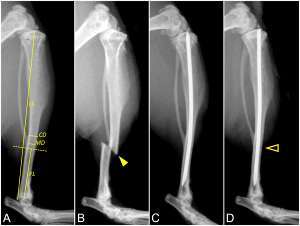
Figure 1: The optimization and generation of a simple tibia fracture. These panels show lateral radiographs of a murine tibia. (A) This panel shows the pre-fracture measurements. The dashed yellow line marks the ideal fracture location. The measurement overlays for the fracture length (FL), limb length (LL), medullary diameter (MD), and cortical diameter (CD) are indicated in the radiograph. (B) This panel shows a fracture location test. The solid arrowhead indicates the level of fracture in a non-stabilized tibia to test the positioning jig parameters. (C) This panel shows a pin length test with a pre-fracture radiograph to test the pin length (PL) and cutting gauge. PL should be 90% of LL, fill the intramedullary canal, and not protrude proximally or distally. (D) This panel shows a post-optimization fracture generation. The arrowhead outline indicates the level of the simple transverse tibia fracture. The pin is not bent at the level of impact. Please click here to view a larger version of this figure.
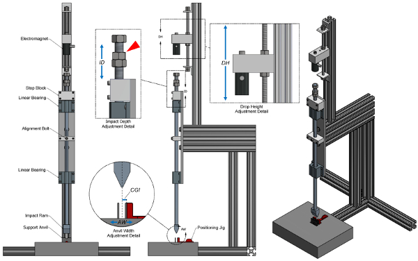
Figure 2: Adjustable fracture device design. This figure shows frontal, lateral, and perspective views of the fracture device. The frontal view includes annotations of major device components. The lateral view includes magnified details illustrating the adjustments for the impact depth (ID), the drop height (DH), and the anvil width (AW). Additional weight can be added to the ram by threading on weights at the top of the impact ram indicated by the red arrowhead. The dotted line in the Anvil Width Adjustment Detail indicates the line of impact. The center of guillotine impact to the outside surface a support anvil (CGI) is used to calculate the depth of the positioning jig to produce an accurate and precise fracture level. The positioning jig is shown in detail in Figure 3A. Please click here to view a larger version of this figure.
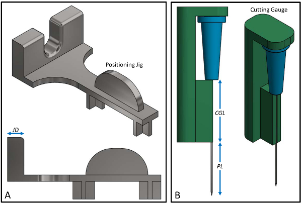
Figure 3: Positioning jig and cutting gauge design. (A) This panel shows details of the mouse positioning jig. The jig depth (JD) can be adjusted to change the fracture location on the limb. Increasing JD will move the fracture proximally and decreasing JD will move the fracture distally. (B) This panel shows details of the needle and the pin cutting gauge. The pin length (PL) should be 90% of the limb length (LL) (Figure 1A). The cutting gauge length (CGL) is derived from subtracting the PL from the needle length. In this example, a cutting gauge has been constructed (CGL = 1.6 cm) to demarcate a 27-G needle (length = 3.175 cm), leaving a PL of 1.58 cm after cutting. Please click here to view a larger version of this figure.
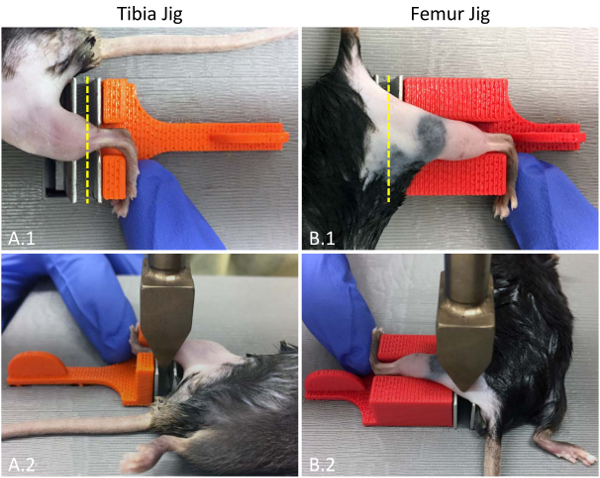
Figure 4: Tibia- and femur-fracture positioning. These are top-down photographs of (A) a mouse tibiaand (B) femur in the positing jig. (A.1) For tibia fractures, the mouse is placed in a supine position with the tibia in the center of the support anvils and the dorsum of the foot pressed against the jig. (B.1) For femur fractures, the mouse is placed in a prone position with the dorsum of the foot pressed against the jig. The dashed yellow line indicates the location of the anvil impact. (A.2 and B.2) The bottom photographs demonstrate the anvil location at the time of impact. The positioning of the researcher's hands should not interfere with the ram actuation. Please click here to view a larger version of this figure.
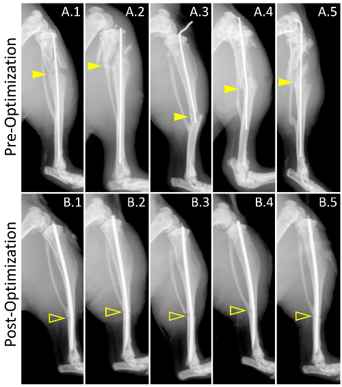
Figure 5. Pre- and post-optimization of the fracture generation. These panels show lateral radiographs of representative fractures from (A) pre-optimization and (B) post-optimization fracture groups. The size of the group was 58 mice. Solid arrowheads and arrowhead outlines indicate the level of fracture in the pre- and post-optimization groups, respectively. (A.1 – A.5) The fractures generated pre-optimization demonstrate a high degree of comminution and fracture-level variability. The pin diameter only partially fills the intramedullary canal with a high degree of length variability. The pin length inconsistency resulted in (A.3) non-stabilized fractures and (A.3 – A.5) pin exposure. A lack of fracture depth control resulted in (A.4) bent pins and contributed to (A.1 – A.5) comminution. In fractures generated post-optimization (see Table 1 for the full set of parameters), the use of a positioning jig (Figure 3A) resulted in a low variability of fracture locations (yellow arrowhead outlines). The optimization of the pin width based on pre-fracture radiographs resulted in a pin selection that filled the intramedullary canal. The use of a pin cutting gauge (Figure 3B) resulted in a consistent pin length. The optimization of the drop height and the impact depth produced simple transverse fractures with no comminution or bent pins. Please click here to view a larger version of this figure.
Abbreviation | Tibia | Femur | ||
Pre-fracture parameters | ||||
Anvil Width (cm) | AW | 0.40 | 0.40 | |
Ram Weight (g) | RW | 272.00 | 272.00 | |
Pre-fracture measurements | ||||
Limb Length (cm), mean±SD | LL | 1.75±0.03 | 1.32±0.05 | |
Cortical Diameter (cm), mean±SD | CD | 0.10±0.00 | 0.15±0.01 | |
Medullary Diameter (cm), mean±SD | MD | 0.05±0.00 | 0.09±0.01 | |
Pin Size (gauge/cm) | PS | 27/3.175 | 23/3.810 | |
Center of Guillotine Impact (cm) = AW / 2 | CGI | 0.20 | 0.2 | |
Fracture Length (cm), mean±SD | FL | 0.56±0.02 | 0.64±0.01 | |
Optimization | ||||
Pin Length (cm) = 0.9 * LL | PL | 1.58 | 1.19 | |
Impact Depth (cm) = 0.75 * CD | ID | 0.07 | 0.11 | |
Cutting Gauge Length (cm) = PS – PL | CGL | 1.60 | 2.62 | |
Jig Depth (cm) = FL – CGI | JD | 0.36 | 0.44 | |
Drop Height (cm) | DH | 2.20 | 4.40 | |
Post-fracture measurements | ||||
Experimental Pin Length (cm), mean±SD | EPL | 1.60±0.06 | 1.19±0.04 | |
Experimental Pin Length to Pin Length (%) | 101.1% | 100.0% | ||
Experimental Fracture Length (cm), mean±SD | EFL | 0.54±0.01 | 0.62±0.06 | |
Experimental Fracture Length to Fracture Length (%) | 97.6% | 97.1% | ||
Simple Transverse Fracture (%) | 9/9 (100%) | 9/9 (100%) |
Table 1: Parameters of the fracture generation before and after the development of the new guillotine system.
Pre-Optimization | Post-Optimization | Test | Significance | |
Experimental Fracture Length (cm), mean±SD | 0.74±0.28 | 0.52±0.05 | t | <0.001 |
F | <0.001 | |||
Experimental Pin Length (cm), mean±SD | 1.47±0.21 | 1.57±0.09 | t | <0.001 |
F | <0.001 | |||
Pin to Bone Length (%), mean±SD | 83.67±11.97 | 92.43±5.29 | t | <0.001 |
F | <0.001 | |||
Simple Transverse Fracture (%) | 46.55 | 98.28 | Pearson | <0.001 |
Table 2: Fracture results before and after the parameter optimization.
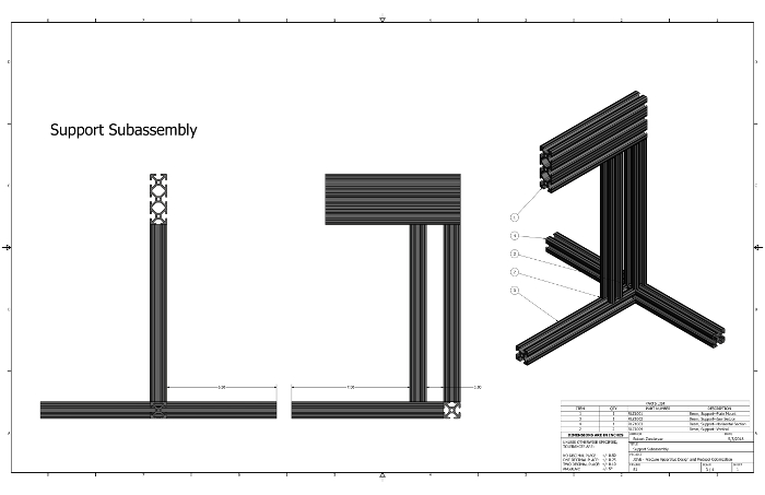
Supplementary Figure 1: Support Subassembly technical drawing. This figure shows a technical drawing for the assembly of the support components. Please click here to view a larger version of this figure.
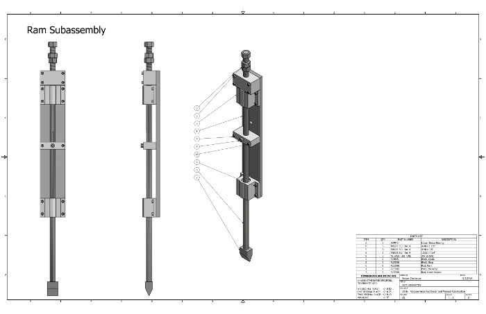
Supplementary Figure 2: Ram Subassembly technical drawing. This figure shows a technical drawing for the assembly of the ram components. Please click here to view a larger version of this figure.
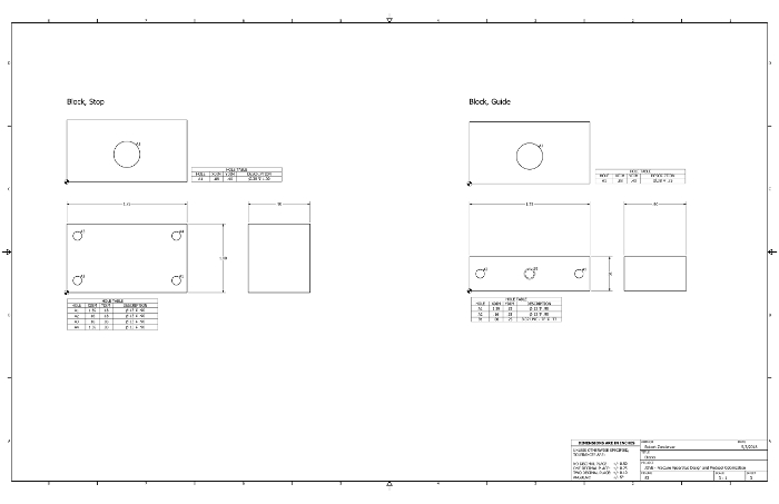
Supplementary Figure 3: Blocks technical drawing. This figure shows a technical drawing which can be used to manufacture the stop and guide blocks for the fracture apparatus. We used aluminum. Please click here to view a larger version of this figure.
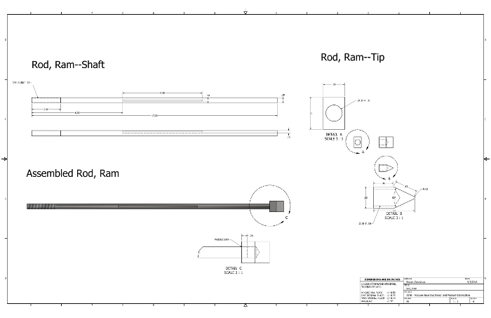
Supplementary Figure 4: Rod, Ram technical drawing. This figure shows a technical drawing which can be used to manufacture the ram for the fracture apparatus. We used stainless steel. Please click here to view a larger version of this figure.
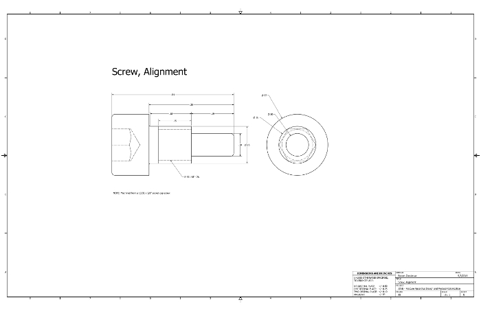
Supplementary Figure 5: Screw, Alignment technical drawing. This figure shows a technical drawing which can be used to modify a socket cap screw to align the ram. Please click here to view a larger version of this figure.
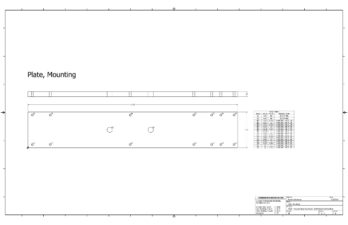
Supplementary Figure 6: Pate, Mounting technical drawing. This figure shows a technical drawing to manufacture the mounting plate for the fracture apparatus. We used aluminum. Please click here to view a larger version of this figure.
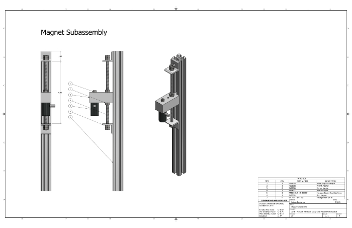
Supplementary Figure 7: Magnet Subassembly technical drawing. This figure shows a technical drawing for the assembly of the magnet components. Please click here to view a larger version of this figure.
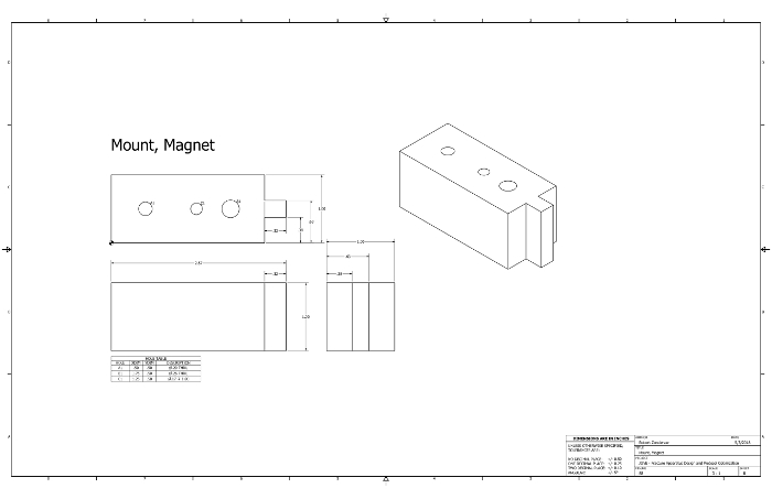
Supplementary Figure 8: Mount, Magnet technical drawing and CAD file. This figure shows (A) a technical drawing and (B) CAD file which can be used to manufacture the magnet mount (file format: *.stl). We 3D-printed the part using polylactic acid (PLA). Please click here to view a larger version of this figure.
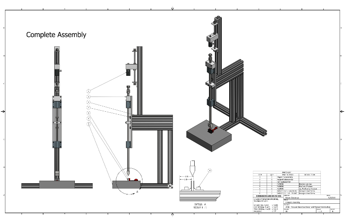
Supplementary Figure 9: Complete Assembly technical drawing and CAD file. This figure shows (A) a technical drawing of the complete fracture assembly with its components and (B) the CAD file (file format: *.iam). Please click here to view a larger version of this figure.
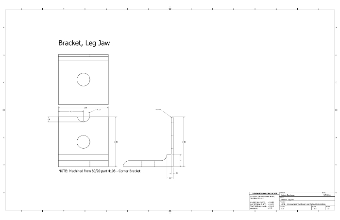
Supplementary Figure 10: Bracket, Leg Jaw technical drawing. This figure shows a technical drawing which can be used to manufacture the leg brackets for the fracture apparatus. The brackets are machined from off-the-shelf 8020 corner brackets. Please click here to view a larger version of this figure.
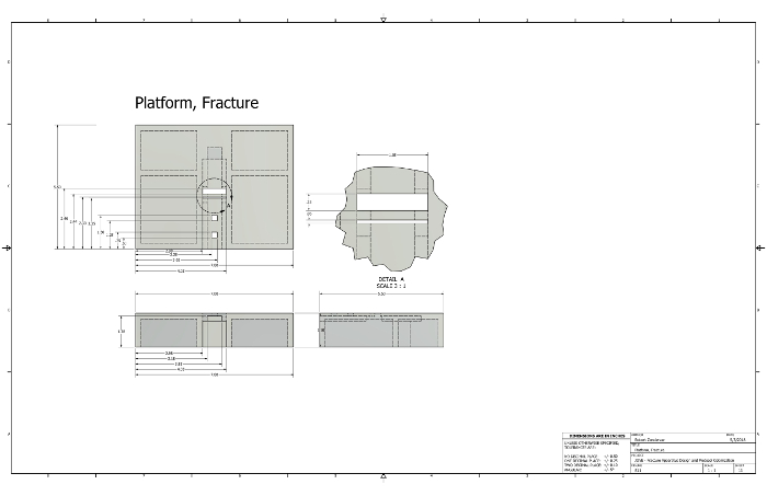
Supplementary Figure 11: Platform, Fracture technical drawing and CAD file. This figure shows (A) a technical drawing and (B) CAD file which can be used to manufacture the fracture platform (file format: *.stl). We 3D-printed the part using polylactic acid (PLA). Please click here to view a larger version of this figure.
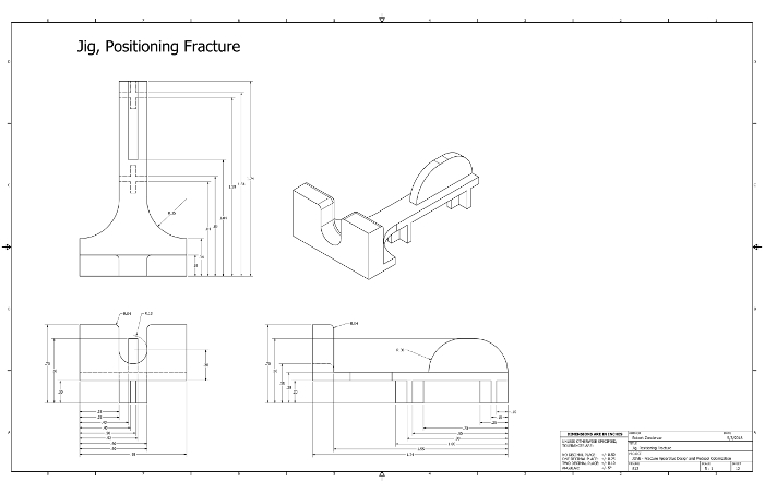
Supplementary Figure 12: Jig, Positioning Fracture technical drawing and CAD file. This figure shows (A) a technical drawing and (B) CAD file which can be used to manufacture the limb-positioning jig (file format: *.stl). We 3D-printed the part using polylactic acid (PLA). Please click here to view a larger version of this figure.
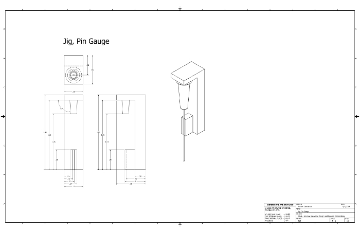
Supplementary Figure 13: Jig, Pin Gauge technical drawing and CAD file. This figure shows (A) a technical drawing and (B) CAD file which can be used to manufacture a pin cutting gauge (file format: *.stl). We 3D-printed the part using polylactic acid (PLA). Please click here to view a larger version of this figure.
This fracture optimization and generation protocol provides researchers with an efficient method to derive at fracture parameters and perform a minimally invasive procedure, which produces precise, repeatable, transverse fractures. Additionally, this protocol establishes a common set of fracture generation parameters, which promotes method consistency amongst researchers. These parameters will enable the creation of a common fracture database to establish fracture standards based on a variety of parameters (e.g., age, sex, gender, and genotype). An optimization of fracture variables significantly decreases sample heterogeneity – reducing the amount of wasted time, lost resources, and unusable data.
To generate accurate and precise fractures, it is vital to establish a standardized set of fracture generation parameters that will produce a high degree of specificity and reduce the variability of fracture locations. In addition to fracture generation, adequate stabilization is also required to promote fracture callus formation and to lessen the probability of non-union. Intramedullary pinning is a common fixation method used to stabilize appendicular long bone fractures both experimentally and clinically. Internally fixated fractures tend to heal indirectly – a process involving tissue differentiation, bone resorption at the fracture surface, and the subsequent fracture union via callus formation and remodeling. These processes can be impeded by movement at the fracture junction and migration of the pin within the medullary cavity. This protocol utilizes a fixation method that reduces the degree of displacement at the fracture site following fixation and limits the extent of pin migration without the use of sophisticated surgical equipment and techniques that can cause unnecessary damage to cortical bone tissue. Generating a set of pin parameters that maximize the intramedullary contact per a specific sample type provides the necessary stability for proper callus formation and bone remodeling.
Once the intramedullary pin has been placed, the next critical step is generating a simple transverse fracture. Protocols that generate fractures via externally applied, blunt-force trauma have the potential to produce comminuted fractures and damage fixation hardware. To mitigate these complications, it is important to control the impact depth, which has to be equal to 0.5x the average cortical diameter of each sample set23. Fracture comminution can also result from excessive force applied during external blunt-force trauma procedures. If the impact velocity exceeds a critical threshold, the speed of the crack propagation will generate stress waves resulting in multiple fracture sites24. It is critical to establish a ram weight and drop height that will generate enough kinetic energy to produce a fracture, while also remaining below the impact velocity threshold for stress wave production, reducing the possibility of comminution. A high-impact velocity will cause a rapid loading of the bone, which produces excessive energy absorption before the fracture is generated25. Upon fracture propagation, the excessive energy absorbed during the loading is released non-linearly, which produces comminution. A lower impact velocity and slower loading of the energy has a higher probability of producing a linear fracture compared to high-impact velocities and rapid loading26. To minimize the incidence of comminution, this protocol uses a standard ram weight of 250 g for mice – this can be adjusted to accommodate a larger species. When working with very young animals or with those with a known bone disease (e.g., osteopenia or osteosclerosis), it may be necessary to decrease the ram weight. It is important to use a consistent ram weight when adjusting the drop height so only one variable is being optimized at a time. Calculations for species-specific ideal impact velocities will produce more consistent fractures by accounting for slight variations in the size and soft tissue morphology of the specimen.
The methods described above eliminate many shortcomings of other fracture generation protocols; however, some aspects may require training to efficiently produce desired results. One possible complication of the procedure is an inaccurate pin placement, potentially causing considerable bone or soft-tissue damage. This is due primarily to the limited visibility of the approach and a lack of sufficient bilateral hand dexterity. An internal fixation without an open incision can require a fair amount of skill from the person performing the procedure. Therefore, it is important that he or she has had sufficient training – on cadavers, if necessary – to avoid excess soft-tissue damage that could cause complications throughout the healing process. Recognizing the structures specified in the protocol (the patellar ligament, tibial plateau, and intercondylar notch of the femur) will help produce a consistent, precise pinning with minimal soft-tissue damage. However, the goal of the described study was not to present a detailed procedure for pin placement, but rather to describe methods for generating ideal fractures.
The use of the cutting gauge is highly recommended to avoid any reaming through the proximal end of the femur or distal end of the tibia. Drilling through the proximal end of the femur could cause unnecessary damage to the soft tissue or bone in the hip, causing mobility and injury complications during the healing process. Similarly, reaming through the distal end of the tibia will damage ankle structures, altering the gait mechanics, loading, and callus formation.
To increase the accuracy of the fracture location, a custom limb-positioning jig can be designed to ensure the proper positioning of the limb within the device. A precise and accurate impact placement is essential to consistently generate fractures at the desired location. Our laboratory currently employs two jigs: one for mid-tibial fractures and the other for mid-femoral fractures, but the versatility of a modular design and 3D printing gives researchers the capability to generate fractures at a variety of locations. The addition of a custom jig designed to generate fractures in a particular location increases both the accuracy and precision of fracture generation by limiting the likelihood of operator errors.
The few limitations of this method are similar to those encountered in other existing closed fracture techniques. Excessive soft tissue or fat can impede the generation of fractures, as seen in older or overweight mice. It is important to note that this is normally due to a lack of force and not to a lack of impact depth. This limitation can be overcome by increasing either the ram weight or the velocity to increase the kinetic energy applied to the fracture site. This method also relies upon internal fixation, which can disrupt the endosteal surface of the bone and affect the healing. While endosteal disruption also occurs clinically with intramedullary nailing, if the contribution of endosteum to fracture repair is being studied, external fixation or plates may be a better option. An additional limitation is the required sample of sacrificial animals to establish the initial parameters; however, as the fracture variables for more sample types are established and the database develops, the need for additional sacrificial samples should decrease.
The described protocol increases the precision of induced traumas through the use of standardized parameters specific to sample type, minimizing the fracture heterogeneity typically seen in closed fracture generation procedures. Most current fracture generation protocols are applicable to only murine species and produce moderately consistent fractures. They often require the use of a specific sample type to obtain optimal results or do not account for variations within strains. The protocol presented here accounts for variation in size or bone morphology that may exist between mouse strains and can be adapted to generate consistent fractures in other species. In addition, the widespread application of this protocol will support the adoption of a standardized fracture language between researchers. Using similar protocols with common variables will improve the method consistency and strengthen comparisons between studies. While the parameters discussed above are specific to murine long bones, there is the potential for the fracture optimization protocol to be used in additional fracture models, further increasing the versatility of a collective fracture generation parameter database. Employing this fracture optimization protocol will increase the production of homogeneous, usable samples by improving the consistency of the fracture location and pattern. The higher percent yield of the samples will decrease the waste of laboratory resources, reduce the number of animals needed, and improve study efficiency.
The authors have nothing to disclose.
The research reported in this publication was supported by the National Institute of Arthritis and Musculoskeletal and Skin Diseases of the National Institutes of Health under award number F30AR071201 and R01AR066028.
Support Subassembly | Supplementary Figure 1 | ||
Beam, Support–Jaw Section | 80/20 | 1003 x 9.00 | w/ #7042 at A, C, in Left End |
Beam, Support–Horizontal Section | 80/20 | 1002 x 14.00 | |
Beam, Support–Vertical 1 | 80/20 | 1050 x 10.50 | w/ #7042 at A in Left End and at A in Right End |
Beam, Support–Vertical 2 | 80/20 | 1010 x 10.50 | w/ #7042 at D, B in Left End and at A in Right End |
Beam, Support–Plate Mount | 80/20 | 1030 x 8.00 | w/ #7036 at Left End |
Beam, Support–Magnet | 80/20 | 1010 x 13.50 | w/ #7042 at A, C, in Right End |
Anchors (3) | 80/20 | 3392 | |
Double Anchor (3) | 80/20 | 3091 | |
Bolt Assembly (6) | 80/20 | 3386 | 1/4-20 x 3/8" |
Button Head Socket Cap Screw (6) | 80/20 | 3604 | 1/4-20 x 3/4" |
Ram Subassembly | Supplementary Figure 2 | ||
Block, Stop | Custom | Supplementary Figure 3 | |
Block, Guide | Custom | Supplementary Figure 3 | |
Rod, Ram | Custom | Supplementary Figure 4 | |
Alignment Screw | Custom | Supplementary Figure 5 | |
Plate, Mounting | Custom | Supplementary Figure 6 | |
Linear Sleeve Bearing (2) | McMaster-Carr | 8649T2 | |
Hex Nut (3) | McMaster-Carr | 92673A125 | 3/8-16 UNC |
Socket Cap Screw (8) | McMaster-Carr | 92196A108 | 4/40 x 3/8" |
Socket Cap Screw (6) | McMaster-Carr | 92196A032 | 4/40 x 1 1/8" |
Socket Cap Screw (1) | McMaster-Carr | 92196A267 | 10/32 3/8" |
Magnet Subassembly | Supplementary Figure 7 | ||
Mount, Magnet | Custom | Supplementary Figure 8 | |
Power Supply | McMaster-Carr | 70235K23 | |
Foot Switch | McMaster-Carr | 7376k2 | |
Electromagnet | McMaster-Carr | 5698k111 | |
Wire – 10 feet | McMaster-Carr | 9936k12 | |
Rod, Magnet | McMaster-Carr | 95412A566 | 1/4" Threaded Rod x 7" |
Corner Bracket (6) | 80/20 | 4108 | |
Socket Cap Screw (1) | McMaster-Carr | 92196A705 | 10/32 1 1/4" |
Hex Nut (4) | McMaster-Carr | 92673A113 | 1/4-20 UNC |
Complete Assembly | Supplementary Figure 9 | ||
Bracket, Leg Jaw (2) | Custom | Supplementary Figure 10 | |
Platform, Fracture | Custom | Supplementary Figure 11 | |
Jig, Positioning-Fracture | Custom | Supplementary Figure 12 | |
Other | |||
Pin Cutter | Medical Supplies and Equipment | 150S | |
Needles | Sigma | Z192430, Z192376 | 23g x 1.5" – mouse femur, 27g x 1.25" – mouse tibia |