Protrusion Force Microscopy: A Method to Quantify Forces Developed by Cell Protrusions
Summary
Here, we detail the experimental techniques used to evaluate the protrusion forces that podosomes apply on a compliant film, from the preparation of the film to the automated analysis of topographical images.
Abstract
In numerous biological contexts, animal cells need to interact physically with their environment by developing mechanical forces. Among these, traction forces have been well-characterized, but there is a lack of techniques allowing the measurement of the protrusion forces exerted by cells orthogonally to their substrate. We designed an experimental setup to measure the protrusion forces exerted by adherent cells on their substrate. Cells plated on a compliant Formvar sheet deform this substrate and the resulting topography is mapped by atomic force microscopy (AFM) at the nanometer scale. Force values are then extracted from an analysis of the deformation profile based on the geometry of the protrusive cellular structures. Hence, the forces exerted by the individual protruding units of a living cell can be measured over time. This technique will enable the study of force generation and its regulation in the many cellular processes involving protrusion. Here, we describe its application to measure the protrusive forces generated by podosomes formed by human macrophages.
Introduction
Animal cells interact physically with the matrix and the other cells that constitute their environment1. This is required for them to migrate, internalize bodies, acquire external information, or differentiate. In such processes, the cell must generate mechanical forces and, as numerous studies have shown over the recent years, the ability of a cell to generate forces and probe its environment influences its biological behavior, directing for instance proliferation or differentiation2,3. In turn, the measurement of cellular forces is a major aid to study the regulation of force generation and understand its implication in cell behavior and tissue fate4,5.
Recent years have witnessed the development of numerous techniques to measure the forces that a cell can exert on its environment6. The majority of these have been instrumental in revealing the traction forces that cells exert as they pull on mobile probes or a deformable substrate. However, the mechanical forces involved in protrusion into the extracellular environment suffer from a lack of measurement techniques and are to date not well characterized.
To overcome this limitation, we present a method to measure forces exerted orthogonally to the substrate. It consists in plating living cells on a thin elastic sheet that can deform in the orthogonal direction, making it possible to measure substrate deformation by the cells and deduce the forces involved. Substrate topography is measured with nanoscale resolution using atomic force microscopy and the evaluation of forces from deformation relies on the knowledge of the geometry of the protrusive cellular structures7,8,9.
Here, we describe the setup and its application to measure the forces generated by podosomes, protrusive adhesion structures formed by macrophages for their mesenchymal migration in three-dimensional environments10,11,12,13,14,15,16,17. We believe that this technique will advance the understanding of force generation and its regulation in the many cellular processes involving protrusion.
Protocol
1. Preparation of Formvar-Coated Grids
- Clean electron microscopy grids with pure acetone and dry them on filter paper. Then clean a microscope slide with pure ethanol, wipe with a lens paper and remove dust with a blower.
- Place an ethanol-cleaned glass slide vertically in the funnel of a film casting device containing a solution of Formvar in the lower part. Cover the top of the funnel.
- Pump 100 mL of Formvar solution (0.5% in ethylene dichloride) with the atomizer bulb until the level reaches two thirds of the slide.
- Keep the slide in the solution for 1 min.
- Open the valve of the device to drain the Formvar solution in a steady stream. A flow rate of 10 to 15 mL/s will yield a Formvar film of 30-80 nm. The thickness of the film is determined by the concentration of the Formvar solution and by the drainage rate.
NOTE: The drainage rate can be controlled by venting the pressure via the air-out valve by slowly opening the valve. The faster the drainage, the thicker the film. In practice, because it is difficult to predict the film thickness from the Formvar flow rate, we prepare several batches of Formvar films and control their thickness by AFM (see Step 2). - Remove the slide from the chamber and dry it delicately on filter paper to remove any liquid Formvar.
- Cut out a 20 mm x 50 mm rectangle from the Formvar film with a razor blade.
- Fill a beaker with clean distilled water and slowly plunge the slide vertically into the water to float off the film: the film should float on the water surface.
- Place dry acetone-cleaned grids on the film, shiny face up.
- Place a round glass coverslip (Ø 12 mm) onto a few of the grids. This coverslip will serve to measure the film thickness (see Step 2).
- Cover a microscope slide with a white sticker resized to fit it. Dip the slide vertically at the border of the floating Formvar film until the whole film adheres to the slide. Remove excess water from the slide with filter paper and let it dry at room temperature overnight.
2. Measurement of Film Thickness
- Cut the Formvar around the coverslip with tweezers to detach it from the slide.
- Mark the location of the grid under the coverslip with a pen.
- Cut the Formvar around the marked grid to detach it from the coverslip. There will therefore be a hole in the remaining Formvar sheet, which will allow to measure the film thickness. Cover the coverslip with PBS and place it on a glass slide on the microscope.
- Mount a silicon nitride cantilever on the AFM glass block, making sure the golden stripe is not covered by the tip of the spring.
NOTE: The sensitivity and spring constant of the cantilever should have previously been calibrated in PBS. - Mount the glass block onto the AFM module, and then place the module onto the microscope.
- Place the Formvar-coated coverslip on the observation chamber and cover it with 500 µL of PBS.
- Scan the border of the hole in the Formvar sheet using AFM in contact mode and a 0.5 nN force set point.
- Use the glass coverslip surface as the reference for height measurements, and evaluate the Formvar thickness as the height of the cross-section (perform at least 10 measurements per Formvar batch).
3. Seeding Cells on Grids
- Under a sterile hood, put a strip (12 mm x 3 mm) of double-sided adhesive tape on a coverslip.
- Cut out a Formvar-coated grid with tweezers and put it upside-down on the adhesive strip (only the rim of the grid needs to be attached to the tape). The Formvar film needs to face the coverslip.
- Put this device in a culture well.
- Place a 10 µL droplet of RPMI without FCS containing 104 macrophages differentiated from human monocytes16.
NOTE: Make sure not to touch the grid with the pipette tip to prevent damaging the Formvar coating. - Incubate for 30 min (37 °C, 5% CO2) to let cells adhere.
- Fill up the well with 2 mL of RPMI containing 10% FCS.
- Incubate the device for 2 h at 37 °C and 5% CO2 to let cells adhere before AFM observation.
4. Topography Measurements of Podosome-Induced Deformations
- Stick two strips of doubled-sided adhesive tape on a glass bottom Petri dish.
NOTE: The distance between the two strips should be smaller than the grid diameter. - Carefully detach the grid plated with macrophages from the adhesive tape.
- Turn the grid upside-down in order to have the cells facing the glass and stick the grid between the two adhesive strips.
- Fix the grid with two new strips of doubled-sided adhesive: the grid will thus be sandwiched between two adhesive strips, leaving the central area of the grid accessible to the AFM tip.
NOTE: Make sure that the grid is well fixed and not twisted; otherwise the AFM cantilever might not be able to approach the Formvar surface. - Fill the Petri dish with 2 mL of pre-heated 37 °C culture medium (RPMI with 10% FCS) supplemented with 10 mM HEPES (pH 7.4).
- Place the culture dish on a 37 °C dish heater.
- Install the dish heater on the AFM stage.
- Let the system stabilize at 37 °C.
- In contact mode with a 0.5 nN force, make a first global image to locate podosomes, and then scan the Formvar topography at 3 Hz with an approximately 20 nm-large pixel.
NOTE: Avoid scanning near the edges of the grid.
Representative Results
The above protocol describes how to prepare the experimental setup to quantify protrusion forces applied by macrophage podosomes on a Formvar substrate. This is achieved using AFM and is illustrated in Figure 1.
When analyzing a topographical image of bulges beneath podosomes using the JPK data processing software, a third-degree polynomial fit should be subtracted from each scan line independently. The maximum height of podosome-induced bumps can be assessed by adding a z color scale on the side of the image. After being exported in TIFF format, the topographical image is further analyzed using a dedicated home-made ImageJ macro available online8. This macro locates bulges on the corrected height image and yields a force map (Figure 2) according to given parameters: Formvar film thickness and podosome ring radius. In addition, the macro also yields a text file with the coordinates, height and computed force value for each detected bulge on the Formvar surface.
This process also applies in the case of time-lapse acquisitions. The macro then tracks each bulge from the middle time point onwards and backwards, requesting user validation if any doubt arises.
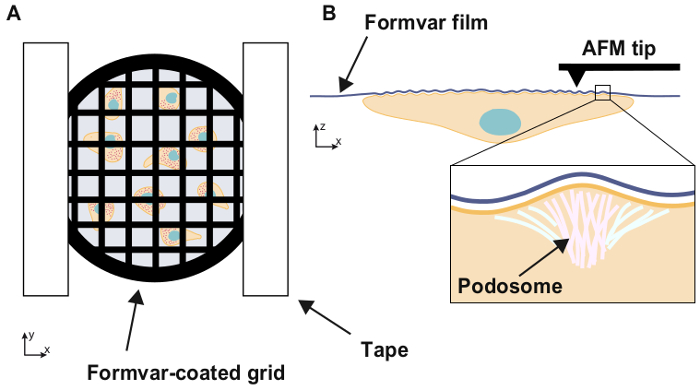
Figure 1: Experimental setup
Schematic illustration of the experimental setup. Cells are seeded on an electron microscopy grid coated with a thin, compliant Formvar film and the grid is placed, cells facing down, inside a Petri dish. When adhering to a substrate, macrophages form submicron highly dynamic adhesion structures called podosomes. The topography of the Formvar film beneath the cells is then imaged using AFM. Podosome apply forces orthogonal to the substrate, which result in bulges on its surface.
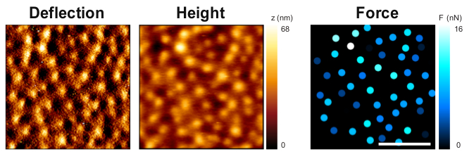
Figure 2: Substrate deformation and forces exerted by podosomes
Topography of the Formvar film on the reverse side of the cells showing deflection (left panel) and height (middle panel, color codes for height). The bulges observed on the film correspond to the deformation by individual podosomes. The force applied by each podosome is evaluated by the model (right panel, each spot corresponds to one podosome and force values are color-coded). Scale bar: 5 µm.
Discussion
Material properties
The choice of the material for the deformable membrane, in our case Formvar, needs to fulfill a few requirements. The material must be transparent to visible light and exhibit limited auto fluorescence to allow observations in bright field and fluorescence microscopy. The roughness of the thin film must be well below 10 nm to avoid any topographical effect on cell adhesion and to allow clear observation of the cell-induced protrusions by AFM imaging. Finally, the stiffness of the membrane, which depends on the Young's modulus and thickness of the material, needs to be high enough to induce the formation of podosomes while keeping some observable deformability for the typical stresses generated at podosome sites which are around 10-100 kPa. Formvar material, prepared in thin films of 30-80 nm is a good compromise between all these constraints. It is worth noticing that by tuning the thickness of the Formvar membrane, its stiffness can be adjusted to study the mechanosensing properties of podosomes7.
Reproducibility and quality of Formvar preparation
Some batches of Formvar present folds on the grid and are therefore unusable: this may be seen beforehand on bright field images. In our experience, we need multiple grids for one condition because sometimes the mounting of the grid is not perfect and the grid moves or gets twisted. The thickness of the Formvar film needs to be adapted to the expected force. The thicker the film, the stiffer it is, but the lower the deformations will be, making observation more difficult. Conversely, the thinner the film, the more fragile it is and the more difficult to manipulate without tearing it.
Influence of the force applied by the cantilever on topography measurements
To obtain a measurement of the film deformation without either affecting the nanomechanical activity of the podosome or deforming the film with the AFM probe, it is crucial to control forces applied during AFM imaging. Indeed, applying excessive force during imaging may lead to an overestimation of the protrusion height and thus of the protrusion force. In other words, there is a need to limit this force far below the stall force of the protruding site. We recommend limiting the applied forces during imaging around to a few hundreds of pico-newtons.
Model for protrusion force evaluation
To convert AFM topographical measurements into force values, it is necessary to define the boundary conditions and to know the spatial configuration of force application. In the case of podosomes, we proposed a model based on the current knowledge of its molecular organisation and verified that this model provided deformation profiles consistent with topographical observations8. More precisely, we modeled the dense core of polymerizing vertical actin filaments surrounded by a ring of adhesion proteins as a central module pushing the substrate and a peripheral module pulling on it. Substrate deformation by these two modules acting was determined using finite element simulations, leading to a force-deformation relationship. Thanks to this numerical approach, we characterized the influence of each geometrical parameter on the force-deformation relationship, showing that ring diameter and substrate thickness needed to be measured precisely. The relationship between the height h of a bulge in the substrate and the force F applied by one podosome may be expressed as F = C0 E/(1-υ2) e3/r2 h, where E = 2.1 GPa is the Young's modulus of Formvar and υ = 0.3 its Poisson ratio7, C0 is a constant equal to 2.7 and e and r respectively denote film thickness and podosome radius8. For each condition, the average value of r was obtained from fluorescence images of podosomes.
Applications of Protrusion Force Microscopy
Protrusion force microscopy was profitably used in macrophages to test the importance of specific proteins on podosome force generation, demonstrate the mechanical role of the podosome ring18 and reveal spatio-temporal correlations of force generation between close neighbours within the network of podosomes8.
Cells have been found to protrude into their environment in several biological processes. Invasive tumor cells use protrusive structures called invadopodia, which are essential to extracellular matrix degradation19. Lymphocytes have been shown to protrude into endothelial cells during their transcellular diapedesis through the endothelium20. Some instances of cell-cell interaction also rely on cellular protruding structures: this is the case for antigen recognition of T cells on endothelial cells21, and for the initiation of cell fusion that leads to multinucleated osteoclasts or to myotubes22,23,24. Finally, internalization processes such as phagocytosis use cellular actin-based structures that project around the target body25. Studying the forces generated by protruding structures will certainly help shed light on the mechanisms at play in these processes.
Disclosures
The authors have nothing to disclose.
Acknowledgements
The authors are grateful to Anna Labernadie, Guillaume Charrière and Patrick Delobelle for their initial contribution to this work and to Matthieu Sanchez and Françoise Viala for their help with video filming and editing. This work has been supported by l’Agence Nationale de la Recherche (ANR14-CE11-0020-02), la Fondation pour la Recherche Médicale (FRM DEQ2016 0334894), INSERM Plan Cancer, Fondation Toulouse Cancer and Human Frontier Science Program (RGP0035/2016).
Materials
| 200 mesh nickel grids | Electron Microscopy Sciences | G200-Ni | |
| Filter paper | Sigma-Aldrich | 1001-055 | |
| Microscope slides | Fisher Scientific | 10235612 | |
| White stickers 26 x 70 mm | Avery | DP033-100 | |
| Film casting device with valve in its outlet | Electron Microscopy Sciences | 71305-01 | |
| Razorblades | Electron Microscopy Sciences | 72000 | |
| Ethanol | VWR | 1.08543.0250 | |
| Acetone | VWR | 20066.321 | |
| Formvar 0.5% solution in ethylene dichloride | Electron Microscopy Sciences | 15820 | |
| 12 mm coverslips | VWR | 631-0666 | |
| Inverted microscope | Carl Zeiss | Axiovert 200 | |
| Atomic Force Microscope | JPK Instruments | NanoWizard III | |
| Temperature-controlled sample holder | JPK Instruments | BioCell | |
| Silicon nitride cantilever with a nominal spring constant of 0.01 N/m | Veeco Instruments | MLCT-AUHW | |
| PBS | Gibco | 14190-094 | |
| Double-sided adhesive tape | APLI AGIPA | 118100 | |
| RPMI 1640 | Gibco | 31870-025 | |
| FCS | Sigma-Aldrich | F7524 | |
| HEPES | Sigma-Aldrich | H0887 | |
| 35 mm glass-bottom Petri dishes | WPI | FD35-100 |
References
- Discher, D. E., Janmey, P., Wang, Y. L. Tissue Cells Feel and Respond to the Stiffness of Their Substrate. Science. 310, 1139-1143 (2005).
- Paszek, M. J., et al. Tensional Homeostasis and the Malignant Phenotype. Cancer Cell. 8, 241-254 (2005).
- Engler, A. J., Sen, S., Sweeney, H. L., Discher, D. E. Matrix Elasticity Directs Stem Cell Lineage Specification. Cell. 126, 677-689 (2006).
- Gilbert, P. M., Weaver, V. M. Cellular Adaptation to Biomechanical Stress across Length Scales in Tissue Homeostasis and Disease. Seminars in Cell & Developmental Biology. 67, 141-152 (2017).
- Vining, K. H., Mooney, D. J. Mechanical Forces Direct Stem Cell Behaviour in Development and Regeneration. Nature Reviews Molecular Cell Biology. , (2017).
- Roca-Cusachs, P., Conte, V., Trepat, X. Quantifying Forces in Cell Biology. Nature Cell Biology. 19, 742-751 (2017).
- Labernadie, A., et al. Protrusion Force Microscopy Reveals Oscillatory Force Generation and Mechanosensing Activity of Human Macrophage Podosomes. Nature Communications. 5, 5343 (2014).
- Proag, A., et al. Working Together: Spatial Synchrony in the Force and Actin Dynamics of Podosome First Neighbors. ACS Nano. 9, 3800-3813 (2015).
- Proag, A., Bouissou, A., Vieu, C., Maridonneau-Parini, I., Poincloux, R. Evaluation of the Force and Spatial Dynamics of Macrophage Podosomes by Multi-Particle Tracking. Methods. 94, 75-84 (2016).
- Cougoule, C., et al. Three-Dimensional Migration of Macrophages Requires Hck for Podosome Organization and Extracellular Matrix Proteolysis. Blood. 115, 1444-1452 (2010).
- Cougoule, C., et al. Blood Leukocytes and Macrophages of Various Phenotypes Have Distinct Abilities to Form Podosomes and to Migrate in 3d Environments. European Journal of Cell Biology. 91, 938-949 (2012).
- Guiet, R., et al. Macrophage Mesenchymal Migration Requires Podosome Stabilization by Filamin A. Journal of Biological Chemistry. 287, 13051-13062 (2012).
- Maridonneau-Parini, I. Control of Macrophage 3d Migration: A Therapeutic Challenge to Limit Tissue Infiltration. Immunology Review. 262, 216-231 (2014).
- Park, H., et al. Tyrosine Phosphorylation of Wiskott-Aldrich Syndrome Protein (Wasp) by Hck Regulates Macrophage Function. Journal of Biological Chemistry. 289, 7897-7906 (2014).
- Van Goethem, E., et al. Macrophage Podosomes Go 3d. European Journal of Cell Biology. 90, 224-236 (2011).
- Van Goethem, E., Poincloux, R., Gauffre, F., Maridonneau-Parini, I., Le Cabec, V. Matrix Architecture Dictates Three-Dimensional Migration Modes of Human Macrophages: Differential Involvement of Proteases and Podosome-Like Structures. Journal of Immunology. 184, 1049-1061 (2010).
- Verollet, C., et al. Hiv-1 Reprograms the Migration of Macrophages. Blood. 125, 1611-1622 (2015).
- Bouissou, A., et al. Podosome Force Generation Machinery: A Local Balance between Protrusion at the Core and Traction at the Ring. ACS Nano. 11, 4028-4040 (2017).
- Lizarraga, F., et al. Diaphanous-Related Formins Are Required for Invadopodia Formation and Invasion of Breast Tumor Cells. 癌症研究. 69, 2792-2800 (2009).
- Carman, C. V., et al. Transcellular Diapedesis Is Initiated by Invasive Podosomes. Immunity. 26, 784-797 (2007).
- Sage, P. T., et al. Antigen Recognition Is Facilitated by Invadosome-Like Protrusions Formed by Memory/Effector T Cells. Journal of Immunology. 188, 3686-3699 (2012).
- Sens, K. L., et al. An Invasive Podosome-Like Structure Promotes Fusion Pore Formation During Myoblast Fusion. Journal of Cell Biology. 191, 1013-1027 (2010).
- Takito, J., et al. The Transient Appearance of Zipper-Like Actin Superstructures During the Fusion of Osteoclasts. Journal of Cell Science. 125, 662-672 (2012).
- Shilagardi, K., et al. Actin-Propelled Invasive Membrane Protrusions Promote Fusogenic Protein Engagement During Cell-Cell Fusion. Science. 340, 359-363 (2013).
- Freeman, S. A., et al. Integrins Form an Expanding Diffusional Barrier That Coordinates Phagocytosis. Cell. 164, 128-140 (2016).
