The manuscript presents a miniature implantable pH sensor with ASK modulated wireless output together with a fully passive receiver circuit based on zero-bias Schottky diodes. This solution can be used as a basis in the development of in vivo calibrated electrostimulation therapy devices and for ambulatory pH monitoring.
Ambulatory pH monitoring of pathological reflux is an opportunity to observe the relationship between symptoms and exposure of the esophagus to acidic or non-acidic refluxate. This paper describes a method for the development, manufacturing, and implantation of a miniature wireless-enabled pH sensor. The sensor is designed to be implanted endoscopically with a single hemostatic clip. A fully passive rectenna-based receiver based on a zero-bias Schottky diode is also constructed and tested. To construct the device, a two-layer printed circuit board and off-the-shelf components were used. A miniature microcontroller with integrated analog peripherals is used as an analog front end for the ion-sensitive field-effect transistor (ISFET) sensor and to generate a digital signal which is transmitted with an amplitude shift keying transmitter chip. The device is powered by two primary alkaline cells. The implantable device has a total volume of 0.6 cm3 and a weight of 1.2 grams, and its performance was verified in an ex vivo model (porcine esophagus and stomach). Next, a small footprint passive rectenna-based receiver which can be easily integrated either into an external receiver or the implantable neurostimulator, was constructed and proven to receive the RF signal from the implant when in proximity (20 cm) to it. The small size of the sensor provides continuous pH monitoring with minimal obstruction of the esophagus. The sensor could be used in routine clinical practice for 24/96 h esophageal pH monitoring without the need to insert a nasal catheter. The "zero-power" nature of the receiver also enables the use of the sensor for automatic in-vivo calibration of miniature lower esophageal sphincter neurostimulation devices. An active sensor-based control enables the development of advanced algorithms to minimize the used energy to achieve a desirable clinical outcome. One of the examples of such an algorithm would be a closed-loop system for on-demand neurostimulation therapy of gastroesophageal reflux disease (GERD).
The Montreal Consensus defines gastroesophageal reflux disease (GERD) as "a condition that develops when refluxing the contents of the stomach causes unpleasant symptoms and/or complications". It may be associated with other specific complications such as esophageal strictures, Barrett's esophagus, or esophageal adenocarcinoma. GERD affects approximately 20% of the adult population, mainly in countries with high economic status1.
Ambulatory pH monitoring of pathological reflux (acid exposure time of more than 6%) allows us to distinguish the relationship between symptoms and acidic or non-acidic gastroesophageal reflux2,3. In patients unresponsive to PPI (proton pump inhibitor) therapy, pH monitoring can answer whether it is pathological gastroesophageal reflux and why the patient does not respond to standard PPI therapy. Various pH and impedance monitoring options are currently offered. One of the newer possibilities is wireless monitoring using implantable devices4,5.
GERD is associated with lower esophageal sphincter (LES) disorder, where the contractions shown during esophageal manometry are not pathological but have a reduced amplitude in long-term GERD. LES consists of smooth muscle and maintains tonic contractions due to myogenic and neurogenic factors. It relaxes due to vagal-mediated inhibition involving nitric oxide as a neurotransmitter6.
Electrical stimulation with two pairs of electrodes was proven to increase the contraction time of the LES in a canine reflux model7. The relaxation of the LES including the residual pressure during swallowing was not affected by both low and high frequency stimulation. High-frequency stimulation is an obvious choice because it requires less power and extends the battery life.
Although electrostimulation treatment (ET) of the lower esophageal sphincter is a relatively new concept in the treatment of patients with GERD, this therapy was shown to be safe and effective. This form of treatment has been shown to provide significant and lasting relief from the symptoms of GERD while eliminating the need for PPI treatment and reducing esophageal acid exposure8,9,10.
The current state-of-the-art pH sensor for diagnostics of GERD is the Bravo device11,12. At an estimated volume of 1.7 cm3, it can be implanted directly into the esophagus with or without visual endoscopic feedback and provides 24 h+ monitoring of pH in the esophagus.
Considering that electrostimulation therapy is one of the most promising alternatives for treating GERD not responding to standard therapy8,13, it makes sense to provide the data from the pH sensor to the neurostimulator. The recent research shows a clear path to future development in this field which will lead to rigid all-in-one implantable devices which will reside at the site of neurostimulation14,15. For this purpose, the ISFET (ion-sensitive field-effect transistor) is one of the best types of sensors because of its miniature nature, the possibility of on-chip integration of a reference electrode (gold in this case), and sufficiently high sensitivity. On silicon, the ISFET resembles the structure of a standard MOSFET (Metal Oxide Semiconductor Field Effect Transistor). However, the gate, normally connected to an electrical terminal, is replaced by a layer of active material in direct contact with the surrounding environment. In the case of pH-sensitive ISFETs, this layer is formed by silicon nitride (Si3N4)16.
The main disadvantage of endoscopically implantable devices is the inherent limitation of the battery size, which may lead to a reduced lifetime of these devices or motivate the manufacturers to develop advanced algorithms that will deliver the required effect at a lower energy cost. One of the examples of such an algorithm would be a closed-loop system for on-demand neurostimulation therapy of GERD. Similar to continuous glucose meters (CGM) + insulin pump systems17, such a system would employ an esophageal pH sensor or another sensor to detect the current pressure of the lower esophageal sphincter together with a neurostimulation unit.
The response to the neurostimulation therapy and the requirements for neurostimulation patterns can be individual13. Thus, it is important to develop independent sensors that could be used either for diagnosis and characterization of the dysfunction or to actively participate in calibrating the neurostimulation system according to the individual requirements of the patients18. These sensors should be as small as possible to not affect the normal functionality of the organ.
This manuscript describes a method of design and fabrication of an ISFET based pH sensor with amplitude-shift keying (ASK) transmitter and a small footprint passive rectenna-based receiver. Based on the simple architecture of the solution, the pH data can be received by an external receiver or even the implantable neurostimulator without any significant volume or power penalty. The ASK modulation is chosen because of the nature of the passive receiver, which is only capable of detection of received RF signal power (often called "received signal strength"). The schematic diagram, which is embedded as Supplementary material, shows the construction of the device. It is powered directly from two AG1 alkaline batteries, which provide a voltage between 2.0-3.0 V (based on the state of charge). The batteries power the internal microcontroller, which utilizes its ADC (analog-to-digital converter), DAC (digital-to-analog converter), internal operation amplifier, and FVR (fixed-voltage reference) peripherals to bias the ISFET pH sensor. The resulting "gate" voltage (the gold reference electrode) is proportional to the pH of the surrounding environment. A stable Ids current is provided by a low-side R2 sensing resistor. The source of the ISFET sensor is connected to the non-inverting input of the operational amplifier, while the inverting input is connected to the output voltage of the DAC module set to 960 mV. The output of the operational amplifier is connected to the drain pin of the ISFET. This operational amplifier regulates the drain voltage so that the voltage difference on the R2 resistor is always 960 mV; thus, a constant bias current of 29 µA flows through the ISFET (when in normal operation). The gate voltage is then measured with an ADC. The microcontroller then powers on the RF transmitter via one of the GPIO (general purpose input/output) pins and transmits the sequence. The RF transmitter circuit involves a crystal and matching network which matches the output to 50 Ω impedance.
For the experiments demonstrated here, we used a pig stomach with a long section of the esophagus mounted in a standardized plastic model. This is a commonly used model for practicing endoscopic techniques such as ESD (endoscopic submucosal dissection), POEM (oral endoscopic myotomy), endoscopic mucosal resection (EMR), hemostasis, etc. Concerning the closest possible anatomical parameters approaching human organs, we used the stomach and esophagus of pigs weighing 40-50 kg.
No living animals were involved in this study. The experiment was performed on an ex vivo model consisting of a porcine esophagus and stomach. The stomach and esophagus were purchased from a local butchery as their standard product. This procedure is in accordance with Czech laws, and we prefer it because of the "3R" principle (Replacement, Reduction, and Refinement).
1. Fabrication of the pH sensor assembly
NOTE: Observe precautions for handling electrostatic discharge (ESD) sensitive components throughout the fabrication of the pH sensor assembly. Be careful when working with the soldering iron.
2. Fabrication of the electronic assembly
NOTE: Observe precautions for handling ESD-sensitive components throughout the fabrication of the electronics. Be careful when working with the soldering iron and hot-air gun.
3. Fabrication of passive rectenna receiver
4. Testing of the device
NOTE: The following steps require the use of chemicals. Study the material safety data sheets of the chemicals beforehand and use proper protective equipment and common lab practices when manipulating them.
5. Endoscopic implantation of the sensor
6. Experiment after implantation
NOTE: The following steps require the use of chemicals. Study the material safety data sheets of the chemicals beforehand and use proper protective equipment and common lab practices when manipulating them.
A device capable of autonomous pH sensing and wireless transmitting of the pH value was successfully constructed, as shown in Figure 8. The constructed device is a miniature model; it weighs 1.2 g and has a volume of 0.6 cm3. The approximate dimensions are 18 mm x 8.5 mm x 4.5 mm. As shown in Figure 15, Figure 16, and Figure 17, it can be implanted to the proximity of the lower esophageal sphincter with a single hemostatic clip; no special accessories are needed. A detailed view of a dissected esophagus with the sensor implanted is shown in Figure 19.
The passive rectenna receiver has an overall footprint of only 22 mm2 even though it is optimized for hand-soldering. When the passive rectenna receiver is put into proximity of the pH sensing device (10 cm) when in an active state (24 h after insertion of batteries until full discharge of the batteries), clear voltage spikes can be observed when the device is transmitting. This is shown in Figure 13. The first two short (75 ms) pulses are synchronization pulses. The distance between the end of the second pulse and the beginning of the third pulse is proportional to the Vgs voltage of the ISFET subtracted by 800 mV (100 ms = 900 mV, 200 ms = 1000 mV, etc.). This voltage linearly translates to the pH of the environment that the sensor is subjected to.
Based on a simple two-point calibration with pH buffers of pH 4 and pH 10 (Table 1), the sensor can return stable and repeatable pH value readings (Table 2). A total of four different solutions with known pH were used-pH 0.6 (160 mM solution of hydrochloric acid in the water, mimicking the stomach acid20) and calibration buffers with pH 4, pH 7, and pH 10. The mean error pH values of the sensor were 0.25 and 0.31 when tested in solutions in beakers and an ex vivo model, respectively. The standard deviations of the errors were 0.30 and 0.36, respectively.
When in the proximity of the transmitter (10 cm), the passive rectenna produces a signal with an amplitude of at least tens of millivolts which can be easily detected by a simple comparator or amplified with an ultra-low-power quiescent current operational amplifier. The effect of a mobile phone antenna with an active GSM call has only a minor negative effect on receiving the data from the sensor, as demonstrated in Figure 14. The mobile phone transmission peaks can be filtered by a simple passive RC/LC (resistor-capacitor/inductor-capacitor) filter as they form a high-frequency part of the signal (their frequency is generally above 500 Hz).
In one of the devices, a short circuit between all three of the ISFET electrodes was intentionally made to show how the device's behavior changes when the device is incorrectly assembled. In this case, no voltage-pH response is observed, and the gate voltage is equal to the drain voltage, which is the battery pack voltage (2-3.2 V). The AD converter, which is referenced to an internal 2.048 V reference, then returns the highest possible value, which translates to 2048 mV. Noise may cause slight fluctuations in the ADC output.
Two variants of firmware that can be programmed to the device were developed and tested. The first one (firmware_10s.zip) is intended for short-term experiments where the pH value is transmitted every 10 s. This provides more data points for the cost of reduced battery life, which is limited to around 24-30 h. The other one (firmware_1min.zip) is intended for long-term experiments. The pH value is transmitted once per min. The lifetime of the sensor with a lower sampling frequency is around 5-6 days. There is also a version of the firmware (firmware-test.zip), which does not include the 24 h delay. This file can be used for testing the correct functionality of the electronics before encapsulation. Alternatively, the delay can be modified by changing the code and recompiling the project. The delay was implemented to allow for a full cure of the epoxy or a possibility when the device is manufactured at a different site than the endoscopic surgery room. With the introduced delay, the useful operating life of the device is maximized.
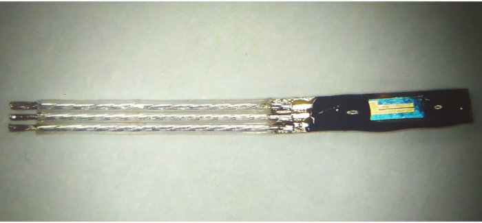
Figure 1: pH sensor assembly before final trimming Please click here to view a larger version of this figure.
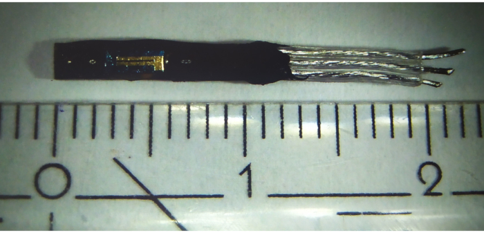
Figure 2: pH sensor assembly after final trimming Please click here to view a larger version of this figure.
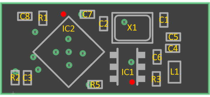
Figure 3: Placement diagram for the implantable sensor (see Table of Materials for component values). Pin 1 is marked as a red dot. Please click here to view a larger version of this figure.
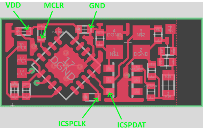
Figure 4: Placement of programming wires Please click here to view a larger version of this figure.
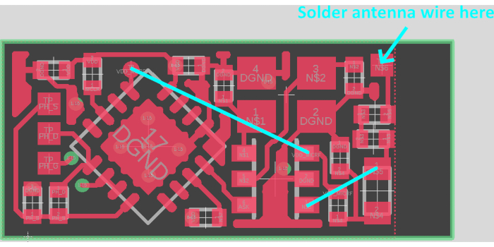
Figure 5: Placement of antenna wire and jumper wires Please click here to view a larger version of this figure.
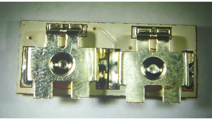
Figure 6: Placement of battery holders Please click here to view a larger version of this figure.
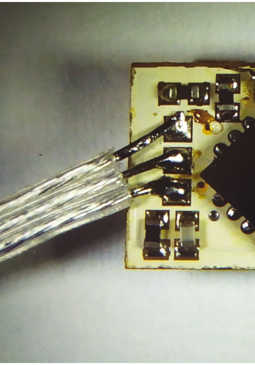
Figure 7: Soldering of the pH sensor assembly to the electronics Please click here to view a larger version of this figure.
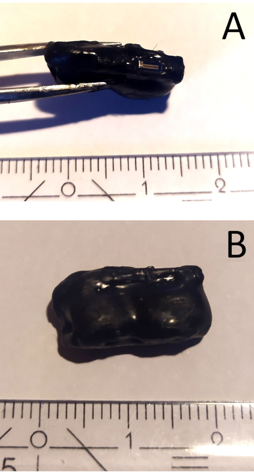
Figure 8: Finished encapsulated sensor. (A) side view, (B) back view Please click here to view a larger version of this figure.
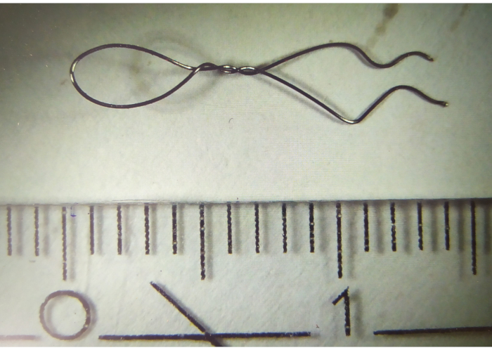
Figure 9: Titanium wire hook Please click here to view a larger version of this figure.
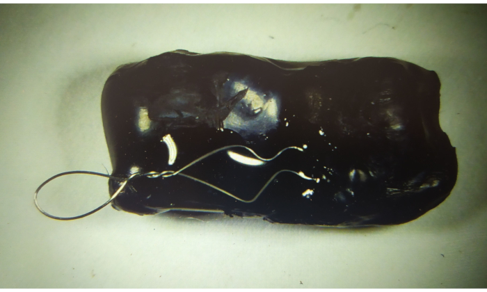
Figure 10: Attachment of the wire hook to the implantable device Please click here to view a larger version of this figure.
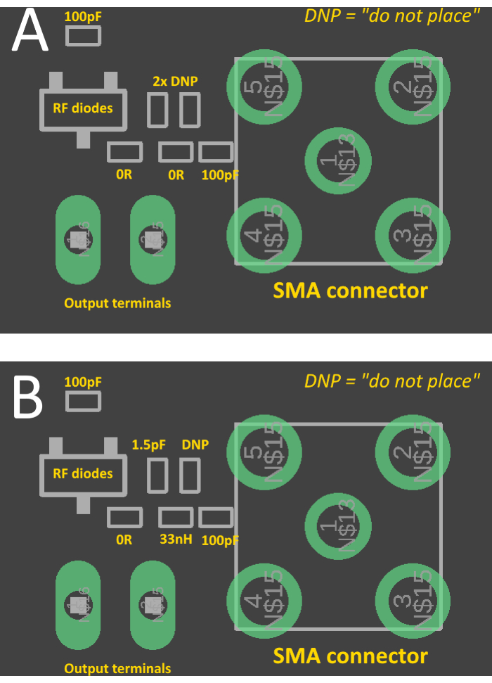
Figure 11: Placement diagram for the rectenna. (A) with matching components, (B) without matching components, ready to be matched with a vector network analyzer Please click here to view a larger version of this figure.
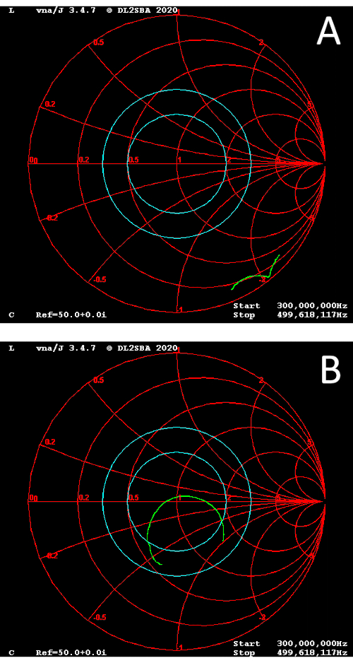
Figure 12: Smith chart. (A) unmatched rectenna, (B) matched rectenna Please click here to view a larger version of this figure.
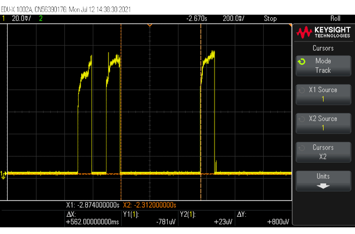
Figure 13: Example response of the rectenna to the incoming data from the sensor Please click here to view a larger version of this figure.
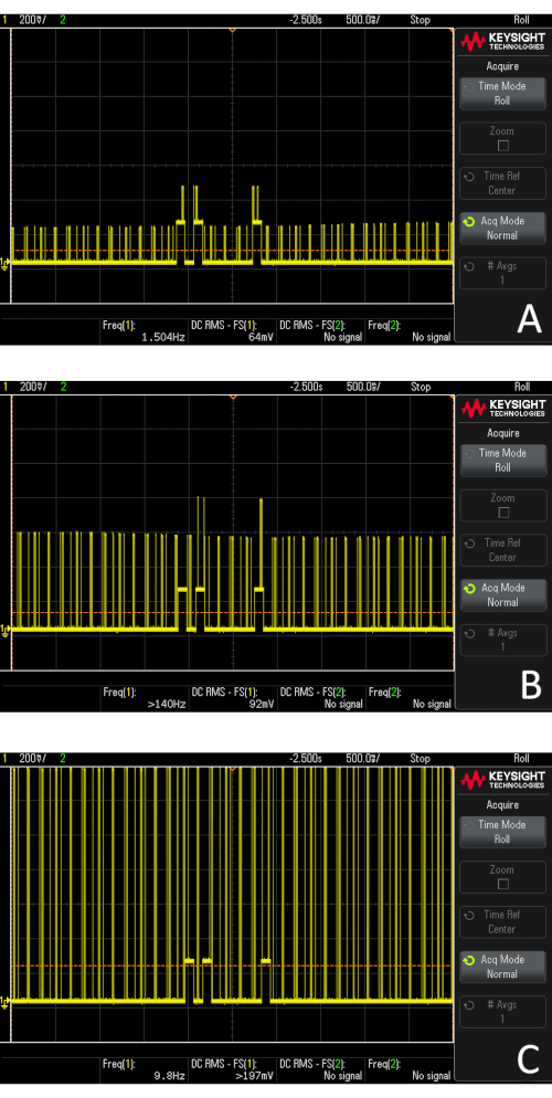
Figure 14: Example response when in the presence of RF noise (nearby phone with an active GSM call). (A) 20 cm between the edge of the phone and receiver, (B) 10 cm between the edge of the phone and receiver, (C) 5 cm between the edge of the phone and receiver Please click here to view a larger version of this figure.
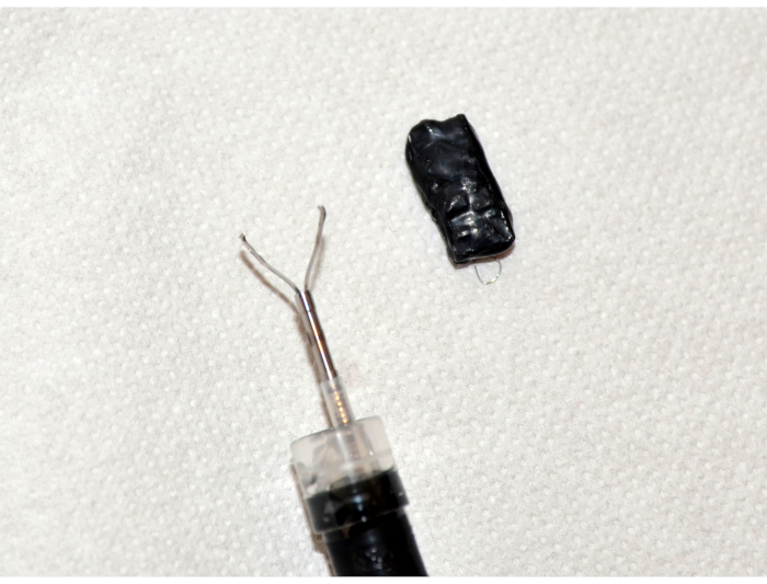
Figure 15: Picture of the endoscope with hemostatic clip and implantable pH sensor Please click here to view a larger version of this figure.
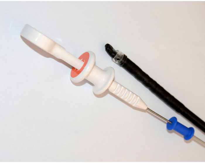
Figure 16: Implantable pH sensor grasped with the hemostatic clip in a cap Please click here to view a larger version of this figure.
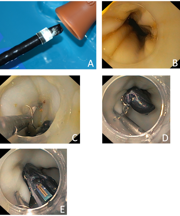
Figure 17: Implantation of the sensor. (A) insertion of the endoscope with the implantable pH sensor into the model, (B) place of implantation – 3 cm above the gastroesophageal junction, (C) preparation of the clip placement, (D) the clip was successfully placed, (E) view of the ISFET pH sensor, implanted to the proximity of lower esophageal sphincter Please click here to view a larger version of this figure.
Figure 18: Injection of the pH buffer solution through the endoscope channel Please click here to view a larger version of this figure.
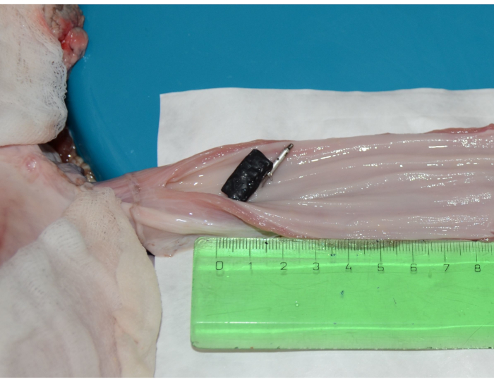
Figure 19: Dissected esophagus of the ex vivo model with the implanted sensor Please click here to view a larger version of this figure.
Calibration data | ||
pH value (cal. meter) [-] | Pulse length [ms] | Calc. volt. output [mV] |
3.98 | 400 | 1200 |
10.01 | 710 | 1510 |
Table 1: Example calibration data
Measured data | ||||
pH value (cal. meter) [-] | Calc. volt. output [mV] | Estimated pH [-] | Error [abs. pH] | Error [%] |
0.62 | 1010 | 0.28 | -0.34 | -54% |
3.98 | 1200 | 3.98 | 0.00 | 0% |
10.01 | 1490 | 9.62 | -0.39 | -4% |
0.62 | 1020 | 0.48 | -0.14 | -23% |
7.01 | 1350 | 6.90 | -0.11 | -2% |
3.98 | 1220 | 4.37 | 0.39 | 10% |
10.01 | 1480 | 9.43 | -0.58 | -6% |
3.98 | 1210 | 4.17 | 0.19 | 5% |
7.01 | 1350 | 6.90 | -0.11 | -2% |
Std. deviation of pH [-] | 0.30 | |||
Mean error [-] | 0.25 |
Table 2: Measured data (test with beakers)
Measured data | ||||
pH value (cal. meter) [-] | Calc. volt. output [mV] | Estimated pH [-] | Error [abs. pH] | Error [%] |
0.62 | 1010 | 0.28 | -0.34 | -54% |
3.98 | 1220 | 4.37 | 0.39 | 10% |
7.01 | 1340 | 6.70 | -0.31 | -4% |
10.01 | 1520 | 10.20 | 0.19 | 2% |
Std. deviation of pH [-] | 0.36 | |||
Mean error [-] | 0.31 |
Table 3: Measured data (test in an ex vivo model)
Supplemental File 1: spreadsheet.xlsx. Spreadsheet for calibrating and processing of the data from the sensor Please click here to download this File.
Supplemental File 2: pcb1.zip. Gerber manufacturing data for the implantable device Please click here to download this File.
Supplemental File 3: pcb2.zip. Gerber manufacturing data for the receiver Please click here to download this File.
Supplemental File 4: firmware_10s.zip. Firmware for the microcontroller with 10 s transmission period Please click here to download this File.
Supplemental File 5: firmware_1min.zip. Firmware for the microcontroller with 1 min transmission period Please click here to download this File.
Supplemental File 6: firmware-test.zip. Firmware for the microcontroller without 24 h pause before activation Please click here to download this File.
Supplemental File 7: Schematic diagram of the electronics Please click here to download this File.
This method is suitable for researchers who work on the development of novel active implantable medical devices. It requires a level of proficiency in the manufacturing of electronic prototypes with surface mount components. The critical steps in the protocol are related to the manufacturing of the electronics, especially populating the PCBs, which is prone to operator error in placement and soldering of small components. Then, correct encapsulation is crucial to prolong the lifetime of the device when exposed to moisture and liquids. The implantation method was designed with simplicity in mind. The risk of perforation of the esophagus or other adverse events during the implantation is minimal. Hemostatic clips are widely used in clinical practice; thus, no special training is needed to perform the implantation.
The device can be easily modified to accompany other sensors with voltage output, i.e., resistive sensors and other ISFET sensors. This gives great flexibility to utilize the whole concept in other areas of research and clinical practice; it is not limited to research of novel methods of treatment of GERD in the case of a pH ISFET sensor.
The constructed device is miniature; it weighs 1.2 g and occupies 60% less volume (0.6 cm3) than the closest commercialized implantable pH sensor. Further miniaturization could be achieved by the integration of the ISFET onto the PCB with wires bonded directly to the PCB. This, however, would significantly increase the barrier of entry in terms of required equipment (it would require at least a manual wire bonder). Thus, a more economically viable alternative with a pre-packaged ISFET sensor by the manufacturer was presented.
As for the power source, silver oxide/alkaline/carbon-zinc 1.5 V cells provide better performance and do simplify the circuit design. The use of primary lithium batteries or Li-Ion batteries in this device form factor could lead to potential problems. Small primary lithium batteries have high output resistance, which would cause significant voltage drops, potentially leading to the brown-out of the microcontroller and RF transmitter. Lithium-ion batteries, on the other hand, are incompatible with 3.3 V microcontrollers (their operating voltage is around 3.0-4.2 V), adding complexity to the circuitry (requirement of a regulator or DC/DC step-down converter). For these reasons, two primary 1.5 V button cells are the best readily available type of battery based on the availability, operating voltage, and sufficiently low output resistance.
The sensor exhibits good accuracy for esophageal pH monitoring; the mean error of pH in an ex vivo model was 0.31 with a standard deviation of 0.36. Despite the washing step with deionized water between each buffer addition, a larger deviation in the ex vivo model could have been caused by minor mixing of the different buffer solutions in the esophagus, which may have altered the pH of the solutions. The sensitivity of the used ISFET pH sensor almost follows the Nernstian slope (-58 mV/pH for 25 °C) at -51.7 mV/pH. The sensitivity is higher than reported in antimony-based pH sensors for monitoring GERD (-45 mV/pH)21.
The delay of 24 h between the insertion of batteries and the start of the wireless transmission routine was introduced to accommodate for encapsulation epoxy curing and instances where the lab for manufacturing of electronics is present at a different location than the endoscopic surgery room. This delay can be altered by modifying the source code and recompiling the firmware.
Depending on the nature of the experiment, which will be done by the researchers, suitable epoxy (cost versus performance) can be chosen. The initial experiments were done with automotive-grade epoxy, which was suitable for initial experiments but not for in vivo experiments from the point of biocompatibility. For survival experiments, a medical-grade epoxy that is ISO10993 compliant for long-term contact with mucous membranes shall be chosen. Also, coatings that improve biocompatibility (e.g., PTFE or parylene) can further reduce the rejection rate of the implant and/or inflammation/irritation of the implantation site.
The fully passive rectenna receiver can be improved by biasing the detector diodes to improve the sensitivity22,23. In case that improved immunity against electromagnetic interference or RF noise is required, the diode detector can be further modified by adding a highly selective band SAW filter between the RF input and diode detector24. If longer-range communication is required, an active ASK receiver (or a software-defined receiver – SDR) can be used. In both cases, the center frequency of the receiver shall be set to 431.73 MHz (frequency of the crystal multiplied by 32 by the PLL in the RF transmitter integrated circuit) and the resolution bandwidth of around 150-250 kHz. The RF output frequency is both voltage and temperature-dependent, and drifts up to 50 kHz from the center frequency were observed during normal operation. The output power in the band can then be monitored and used to decode the pH value according to the protocol. The use of an active receiver is recommended for initial testing. If used inside an implantable device, it comes with an increase in complexity and a major energy penalty. It cannot provide the "zero-power" advantage that the Schottky detector provides.
Today, virtually all active implantable medical devices are not designed with interoperability in mind. Their configuration is done manually by a surgeon or practitioner25 and does not cooperate. The implantable device presented in this method together with a passive rectenna receiver, shows a way to realize seamless data transfer from a disposable sensor to another implantable device. While commercially available RF modules for implantable devices based on the heterodyne concept exist, the receiver mode is very power demanding26. With the presented solution, no active receiver in the neurostimulator is required; the circuit can be built to be completely passive. The main advantages of taking real-time patient data into account are to improve the efficacy of the therapy and significantly lower the power consumption. For example, in the case of GERD therapy, a pH sensor presented in the manuscript can be implanted above the lower esophageal sphincter after the implantation of the stimulator to automatically adapt the neurostimulation pattern to maximize the effect of the therapy while minimizing the power consumption. As the implantation of the sensor to the inner esophageal wall is prone to dislocation after several days, it makes more sense to design the sensor as a battery-powered one. Thanks to the higher volumetric energy density of primary batteries, the use of a primary power source is superior to a sensor that contains a wireless power receiving circuit, charging coil, and capacitor-based energy storage. The overall efficiency of the wireless charging is also heavily dependent on the spatial orientation of the coils, which would introduce yet another difficulty to the design. Wireless charging provides benefits to the permanently implanted microneurostimulators, i.e., to the submucosa14. The battery-powered pH sensor provides a possibility to optimize the energy consumption of such a microneurostimulator. Instead of permanent/regular neurostimulation of the sphincter, the pH sensor can show when the stimulation is needed (i.e., primarily at night and/or which hours of the day) and what power output is the lowest possible to achieve sufficient lower esophageal sphincter pressure. These closed-loop or quasi-closed-loop implantable systems can become a promising alternative to current traditional systems, offering smaller implantable devices with less-invasive implantation and improving the treatment's efficacy.
The authors have nothing to disclose.
The authors gratefully acknowledge Charles University (project GA UK No 176119) for supporting this study. This work was supported by the Charles University research program PROGRES Q 28 (Oncology).
AG1 battery | Panasonic | SR621SW | Two batteries per one implant |
Battery holder | MYOUNG | MY-521-01 | |
Copper enamel wire for the antenna | pro-POWER | QSE Wire – 0.15 mm diameter, 38 SWG | |
Epoxy for encapsulation | Loctite | EA M-31 CL | Two-part medical-grade ISO10993 compliant epoxy |
FEP cable for pH sensor | Molex / Temp-Flex | 100057-0273 | |
Flux cleaner | Shesto | UTFLLU05 | Prepare 5% solution in deionized water for cleaning by sonication |
Hemostatic clip | Boston Scientific | Resolution | |
Hot air gun + soldering iron | W.E.P. | Model 706 | Any soldering iron capable of soldering with tin and hot-air gun capable of maintaining 260 °C can be used |
Impedance matching software | Iowa Hills Software | Smith Chart | Can be downloaded from http://www.iowahills.com/9SmithChartPage.html – alternatively, any RF design software supports calculation of impedance matching components |
ISFET pH sensor on a PCB | WinSense | WIPS | Order a model pre-mounted on a PCB with on-chip gold reference electrode |
Laboratory pH meter | Hanna Instruments | HI2210-02 | Used with HI1131B glass probe |
Microcontorller programmer | Microchip | PICkit 3 | Other PIC16 compatible programmers can be also used |
Pig stomach with esophagus | Local pig farm | Obtained from approx. 40–50 kg pig | It is important that the stomach includes a full length of the esophagus. |
Printed circuit board – receiver | Choose preferred PCB supplier | According to pcb2.zip data | One layer, 0.8 mm thickness, FR4, no mask |
Printed circuit board – sensor | Choose preferred PCB supplier | According to pcb1.zip data | Two-layer with PTH, 0.6 mm thickness, FR4, 2x mask |
Receiver – 0R | Vishay | CRCW04020000Z0EDC | See Figure 12 and Figure 13 for placement |
Receiver – 1.5 pF | Murata | GRM0225C1C1R5CA03L | See Figure 12 and Figure 13 for placement |
Receiver – 100 pF | Murata | GRM0225C1E101JA02L | See Figure 12 and Figure 13 for placement |
Receiver – 33 nH | Pulse Electronics | PE-0402CL330JTT | See Figure 12 and Figure13 for placement |
Receiver – RF schottky diodes | MACOM | MA4E2200B1-287T | See Figure 12 and Figure 13 for placement |
Receiver – SMA antenna | LPRS | ANT-433MS | |
Receiver – SMA connector | Linx Technologies | CONSMA001 | See Figure 12 and Figure 13 for placement |
Sensor – C1 | Murata | GRM0225C1H8R0DA03L | 8 pF 0402 capacitor |
Sensor – C2 | Murata | GRM0225C1H8R0DA03L | 8 pF 0402 capacitor |
Sensor – C3 | Murata | GCM155R71H102KA37D | 1 nF 0402 capacitor |
Sensor – C4 | Murata | GRM0225C1H1R8BA03L | 1.8 pF |
Sensor – C5 | Vishay | CRCW04020000Z0EDC | Place 0R 0402 resistor or use to match the antenna |
Sensor – C6 | Murata | GRM155C81C105KE11J | 1 uF 0402 capacitor |
Sensor – C7 | Murata | GRM155C81C105KE11J | 1 uF 0402 capacitor |
Sensor – C8 | Murata | GRM022R61A104ME01L | 100 nF 0402 capacitor |
Sensor – IC1 | Microchip | MICRF113YM6-TR | MICRF113 RF transmitter |
Sensor – IC2 | Microchip | PIC16LF1704-I/ML | PIC16LF1704 low-power microcontroller |
Sensor – R1 | Vishay | CRCW040210K0FKEDC | 10 kOhm 0402 resistor |
Sensor – R2 | Vishay | CRCW040233K0FKEDC | 33 kOhm 0402 resistor |
Sensor – R3 | Vishay | CRCW04021K00FKEDC | 1 kOhm 0402 resistor |
Sensor – R5 | Vishay | CRCW040210K0FKEDC | 10 kOhm 0402 resistor |
Sensor – X1 | ABRACON | ABM8W-13.4916MHZ-8-J2Z-T3 | 3.2 x 2.5 mm 13.4916 MHz 8 pF crystal |
Titanium wire | Sigma-Aldrich | GF36846434 | 0.125 mm titanium wire |
Vector network analyzer | mini RADIO SOLUTIONS | miniVNA Tiny | Other vector network analyzers can be used – the required operation frequency is 300–500 MHz, resolution bandwidth equal or lower than 1 MHz, output power of no more than 0 dBm and dynamic range preferably better than 60 dB for the receiving front-end |