Summary

High-Throughput Bioprinting Method for Modeling Vascular Permeability in Standard Six-well Plates with Size and Pattern Flexibility

Published: August 16, 2024
doi:

Summary

We present a protocol for high-throughput production of vascular channels with flexible sizes and desired patterns on a standard six-well plate using 3D bioprinting technology, referred to as vessels-on-a-plate (VOP). This platform has the potential to advance the development of therapeutics for the disorders associated with compromised endothelium.

Abstract

Vascular permeability is a key factor in developing therapies for disorders associated with compromised endothelium, such as endothelial dysfunction in coronary arteries and impaired function of the blood-brain barrier. Existing fabrication techniques do not adequately replicate the geometrical variation in vascular networks in the human body, which substantially influences disease progression; moreover, these techniques often involve multi-step fabrication procedures that hinder the high-throughput production necessary for pharmacological testing. This paper presents a bioprinting protocol for creating multiple vascular tissues with desired patterns and sizes directly on standard six-well plates, overcoming existing resolution and productivity challenges in bioprinting technology. A simplified fabrication approach was established to construct six hollow, perfusable channels within a hydrogel, which were subsequently lined with human umbilical vein endothelial cells to form a functional and mature endothelium. The computer-controlled nature of 3D bioprinting ensures high reproducibility and requires fewer manual fabrication steps than traditional methods. This highlights VOP’s potential as an efficient high-throughput platform for modeling vascular permeability and advancing drug discovery.

Introduction

The vascular network throughout the human body functions as a crucial transport barrier by dynamically regulating the exchange of molecules and cells between the blood and surrounding tissues. This regulation is essential for preventing tissue edema and enabling selective nutrient and cell exchange, thus supporting tissue metabolism and homeostasis1. Altered endothelial permeability, a factor in many health conditions, affects both disease severity and treatment efficacy2. Vascular endothelium acts as a selective barrier, facilitating the transfer between vessels, tissues, and organs. This regulation involves several mechanisms, such as the basic filtering of solutes and small molecules, intentional disruption of the vascular barrier, and the influence of molecules such as prostaglandins and growth factors on permeability levels3.

Key factors in this regulation include endothelial cell junctions, the migration of leukocytes, and the functionality of the blood-brain barrier4. Given its complexity, the process varies across different environments, involving various blood vessel types and utilizing distinct anatomical pathways. Comprehending the biological underpinnings of vascular permeability is crucial for devising therapeutic approaches to treat conditions associated with abnormal vascular permeability. Maintaining vascular permeability is crucial for the health of the vascular system and surrounding tissues; consequently, impairment of this function leads to endothelial dysfunction, a state in which the endothelium loses its normal functionality.

Endothelial dysfunction is a precursor to several prevalent human diseases, including hypertension, coronary artery disease, diabetes, and cancer5,6,7. This condition can present in several ways, including decreased vasodilation, increased vessel permeability, and a tendency toward a pro-inflammatory state. This pathological state is the earliest stage of several critical cardiovascular issues, such as coronary artery disease, stroke, and peripheral artery disease8, which continue to be the leading causes of mortality in the United States1. Endothelial dysfunction affects cardiovascular health as well as the blood-brain barrier (BBB) and plays a major role in the progression of various neurological disorders. Dysfunction can increase BBB permeability, thus allowing toxins, pathogens, and immune cells to infiltrate into the central nervous system and contributing to neurological disorders such as stroke, Alzheimer's disease, multiple sclerosis, and brain infections9.

Endothelial dysfunction in diabetes is marked by the compromised ability of the endothelium to regulate vascular tone and produce vasodilator mediators, such as nitric oxide, leading to impaired vasodilation10. This condition is exacerbated by hyperglycemia-induced pathways such as protein kinase C activation and oxidative stress, contributing significantly to the progression of diabetic vascular disease11. Moreover, an inflammatory environment has been found to enhance tumor cell adhesion to brain microvascular endothelial cells while a leaky endothelium has been reported to be a major factor in cancer metastasis12,13. The geometry of blood vessels has been found to directly influence brain cancer metastasis. Tumor cells preferentially attach to areas of greater blood vessel curvature7. This finding underscores the importance of vascular geometry in cancer metastasis. More importantly, in conditions such as fibrosis and cancer, disrupted endothelial barrier function not only plays a role in disease development but also hinders treatment effectiveness by hindering adequate drug delivery14. Research on vascular permeability is crucial for advancing cardiovascular disease treatment and offering insights into managing other diseases involving compromised vascular function.

Given the crucial role of vascular permeability in health and disease, considerable research has focused on examining the selective nature of the endothelial barrier for therapeutic development by using animal models, alongside traditional 2D and 3D in vitro testing platforms. However, animal models have limitations because of species-specific differences and ethical issues, as well as high costs15,16. For instance, Pfizer, in 2004, stated that over the previous 10 years, it had spent over $2 billion on drug developments that showed promising effects in animal models but eventually failed in advanced human testing stages17. Moreover, traditional 2D models do not accurately mimic the three-dimensional (3D) architecture and the complex geometric structure of vascular channels.

With advancements in biofabrication technologies, extensive efforts have been aimed at fabricating vascular channels while recapitulating 3D architecture. Microscale vascular channels can be effectively fabricated within microfluidic chips by using soft lithography, thus offering an advantage of real-time analysis18,19. Alternative methods, such as hydrogel casting or wrapping cell sheets around a mold or mandrel, can be used to create freestanding tubular structures with the desired diameter20,21. However, these methods have limitations; for example, microfluidic chips are restricted to microchannel configurations, and hydrogel casting around a mold does not effectively replicate multiple geometries.

With the emergence of 3D bioprinting technology22, replicating complex geometries by precisely depositing various extracellular matrix (ECM)-based hydrogel materials has become possible23,24. Some bioprinting methods, such as those using concentrically arranged nozzles, e.g., coaxial and triaxial25,26, cannot create bifurcated tubes; however, complex structures can be achieved with sacrificial patterning methods27. None of these bioprinting methods have been demonstrated to enable high-throughput in vitro modeling-a crucial requirement for pharmacological research in drug discovery. Herein, we present a method for efficiently fabricating endothelialized vascular channels with efficient control over dimensions.

We established a straightforward approach using commercially available six-well plates, combined with a sacrificial patterning method in which a bioprinter fabricates vascular channels of desired sizes and patterns within an ECM hydrogel. Human umbilical vein endothelial cells (HUVECs) were seeded to endothelialize these channels and evaluate the functionality of endothelium through a permeability assay. This design enables pumpless perfusion by creating media reservoirs on both sides of the channel and uses gravity-driven flow with the help of a commonly used 2D rocker to mimic the dynamic culture. This approach eliminates the need for peristaltic pumps and facilitates the scalability of this platform for high-throughput applications. The computer-controlled nature of 3D bioprinting technology also streamlines the fabrication process, thus decreasing the likelihood of errors during manufacturing. The VOP model shows promise as a valuable tool for pharmacological testing in drug discovery.

Protocol

1. Generation of G-code for the bioprinter

  1. To generate and visualize the printing path, visit an online G-code simulation tool (e.g., NCviewer).
  2. Click the New File icon on the interface to create a new G-code file.
  3. Generate a printing path by manually writing the G-code commands for the sacrificial channel and the silicon chamber. Use the dimensions of a standard six-well plate as a reference for creating the geometry.
    NOTE: G-code used here is based on Computer Numerical Control (CNC) code. The functions of each command are provided in Supplemental Table S1. The six-well plate format was selected because of its compatibility with commercial microplate readers and microscopy setups and its ability to accommodate adequate volumes of media to support endothelium maturation, thereby minimizing the need for frequent media changes. This fabrication protocol can also be adapted for use with other standard well plates.
  4. Once the G-code is completed, click the Save File icon on the interface to download the file with a .nc extension.
    NOTE: Any other available G-code generation algorithm can be used to generate the printing paths. The geometry of the vascular channel can be manipulated in this G-code.

2. Preparation of sacrificial and silicon chamber inks

NOTE: Sources for all materials used in this protocol are listed in the Table of Materials.

  1. Combine two types of silicone polymers, SE1700 and polydimethylsiloxane (PDMS), in a 10:2 ratio. Add curing agent of each polymer in a ratio of 10:1, polymer to curing agent.
  2. Use a planetary mixer to thoroughly mix and degas the polymer mixture at 2,000 rpm.
  3. With a spatula, transfer the mixed silicone polymer into a 10 mL disposable syringe. Centrifuge the loaded syringe at 400 × g for 3 min at 5 °C to ensure uniform consistency and avoid bubbles during printing.
    NOTE: The chamber ink should be used within 2 h after the addition of the curing agents to ensure optimal printing quality. Store the syringe at 5 °C while preparing for printing. This process helps slow ink curing, which can otherwise alter the printing parameters.
  4. Weigh Pluronic F-127 (PF127) to prepare a 40% (w/v) stock solution of PF127 in distilled water.
  5. Mix the PF127 solution in a planetary mixer for 3 min at 400 × g to achieve homogeneity. Keep the homogenized mixture at 4 °C for complete dissolution of PF127.
  6. Prepare a thrombin stock solution of 1,000 units/mL in Dulbecco's phosphate-buffered saline (DPBS).
    NOTE: Store thrombin stock solution in 100 µL aliquots to avoid repeated freeze-thaw cycles. The aliquots should be stored at -20 °C for no longer than 6 months.
  7. Before printing, prepare sacrificial ink by mixing thrombin at a 1:10 dilution with PF127 to a final working concentration of 36% (w/v) for PF127 and 100 units/mL for thrombin. To prepare 1 mL of sacrificial ink, mix 100 µL of thrombin stock solution with 900 µL of PF127 stock solution.
    NOTE: When preparing the sacrificial ink for printing a single plate, a total volume of 1 mL is more than sufficient.

3. Fabrication process

  1. Before starting the fabrication process, treat a six-well plate with oxygen (O2) plasma at a strength of 100 watts for 1 min.
  2. Follow the procedure outlined in section 2 to prepare both the sacrificial and silicon inks, ensuring that the inks are free of bubbles and homogeneously mixed for consistent printing. Carefully load the inks in the printhead of the bioprinter. Set the temperature of the bioprinter's head to 37 °C for the sacrificial ink and 5 °C for the silicon ink.
  3. Attach a 22 G double-screw thread tapered nozzle to the silicon syringe. For the sacrificial ink, choose the nozzle size according to the desired channel diameter.
    NOTE: Here, we demonstrated three sizes of nozzles: 18 G, 20 G, and 22 G. Optimal printing parameters including printing pressure and printhead speed, are outlined in Table 1.
  4. Load the desired G-code and press the servo ready function on the bioprinter's software interface for 3 s. Position the plate on the stage at the starting point of the G-code and click start to initiate the printing process.
    NOTE: Typically, fabrication of one plate containing six chambers requires approximately 1 h and 10 min. Step 3.4, involving the loading and execution of the G-code, is subject to variation depending on the specific bioprinter used. Ensure that sterile conditions are maintained while using the bioprinter to avoid contamination.
  5. Place a lid over the plate and transfer the plate to a humidified CO2 incubator at 37 °C for 72 h to cure the silicon chambers.
    NOTE: Although the silicon curing may occur at a slower rate inside the incubator, the plate must not be placed inside a dry oven.

4. Hydrogel preparation and channel embedding

  1. Prepare a 50 mL conical tube containing 20 mL of 1x PBS. Place 0.01 g of lithium phenyl-2,4,6-trimethylbenzoylphosphinate (LAP) into the conical tube to make a 0.05% (w/v) LAP solution. Vortex it until the powder is completely dissolved.
    NOTE: Wrap the conical tube in foil to prevent exposure to light. Store the LAP stock solution at 4 °C.
  2. Add 3 g of gelatin methacrylate (GelMA) and 0.2 g of fibrinogen to 20 mL of LAP solution to achieve a final concentration of 15% GelMA and 1% fibrinogen (referred to as GelFib). Place the mixture in a 37 °C water bath, and periodically vortex mix until the solution is fully dissolved.
  3. After fabrication as outlined in Section 3, add 300 µL of prewarmed GelFib into each hydrogel chamber to embed the sacrificial pattern. Rapidly crosslink the GelMA with ultraviolet (UV) light at a wavelength of 405 nm with an intensity of 85 mW/cm2 for 120 s. Repeat this procedure for all other wells.
    NOTE: Fibrinogen crosslinks rapidly upon contact with the sacrificial pattern containing thrombin. We recommend adding hydrogel and performing UV crosslinking individually for each well to avoid unwanted gelation of GelMA at room temperature. Additionally, sterile conditions should be maintained to prevent contamination during the UV curing process.
  4. Add 1 mL of DPBS to each side of the vascular channel in each well, and keep the plate at 4 °C for 15 min to liquefy the PF127.
  5. After 15 min, suction off the DPBS, and repeat step 4.5 3x for complete washing of PF127.
  6. Before introducing cells into the channels, perfuse DMEM F12 containing 1% Matrigel for 30 min through the channels to enhance cell attachment.

5. HUVEC culture

  1. Prewarm endothelial cell growth medium (ECGM) in a 37 °C water bath for 30 min.
  2. Meanwhile, retrieve a vial of cryopreserved HUVECs from the nitrogen tank, gently loosen the vial's cap, and then retighten it to release nitrogen from the threads. Immediately thaw the cells by submerging the vial in a 37 °C water bath for 2 min, ensuring that a small amount of ice remains inside the vial. Rinse the vial with 70% ethanol to prevent contamination.
    NOTE: Wear safety goggles when retrieving cells from the nitrogen tank. The vial's cap must be kept above the water level during this process.
  3. Prepare a 15 mL conical tube containing 5 mL of prewarmed ECGM. With a micropipette, carefully transfer the thawed cells from the vial into the conical tube. To ensure that no cells are left behind, add 1 mL of fresh prewarmed medium to the cryovial, rinse the inside, and transfer any remaining cells into the conical tube.
  4. Centrifuge the conical tube at 200 × g for 3 min to obtain a cell pellet. Discard the supernatant, resuspend the cells in 10 mL of fresh medium, transfer the cells to a T75 flask, and place the flask inside a 37 °C humidified CO2 incubator.
    NOTE: This step is important to remove dimethyl sulfoxide present in the freezing medium in the cryovial through centrifugation.
  5. Refresh the medium every other day until cells reach 80-90% confluency.

6. Endothelialization of channels

  1. Prewarm ECGM, DPBS, trypsin-neutralizing solution, and trypsin ethylenediaminetetraacetic acid (TE) in a 37 °C water bath for 30 min.
  2. At 90% confluency, rinse the cells in a T75 flask with 10 mL of DPBS, add 1 mL of 0.25% TE to the flask, and incubate it for 3 min.
  3. Gently tap the sides of the flask and add 5 mL of trypsin-neutralizing solution to neutralize the TE. Transfer the cells to a 15 mL conical tube. Use 5 mL of fresh ECGM to collect the remaining cells and add them to the conical tube.
  4. Centrifuge the conical tube at 250 × g for 3 min to collect the cell pellet.
  5. Discard the supernatant and resuspend the cell pellet in 1 mL of fresh ECGM. Count the cells with a hemocytometer and repeat Step 6.4 to obtain a cell pellet. Resuspend 3 million cells in 90 µL of fresh ECGM.
  6. Before introducing the cell suspension into the channel, briefly vacuum suction the channel to clear the lumen.
    NOTE: Avoid prolonged suction of the channel to avoid damaging its integrity.
  7. Gently load the channel with a cell suspension at a seeding density of 0.5 million cells per well. Use a micropipette to add ~15 µL of this suspension to fill the channel.
    NOTE: The seeding density may vary depending on the size of the channel. This density is optimized for a channel printed with a 20 G nozzle and an internal diameter of approximately 900 µm.
  8. Place the plate flat inside the incubator for 2 h. Subsequently, invert the plate to 180°, maintaining it in a flat position for the following 2 h.
  9. After 4 h, wash the channel with DPBS to remove non-adherent and dead cells. Add 2 mL of fresh ECGM to each well (1 mL to each side of the channel). Start the dynamic culture on a rocker at a 10° tilt angle and 5 rpm by positioning the plate on the rocker with the channels parallel to the direction of rocking. Refresh the growth medium every other day.
    NOTE: Dynamic culture enhances medium exchange between the reservoirs and channels and helps the cells proliferate overnight.

7. Endothelium maturation assessment

  1. Prewarm ECGM and DPBS in a 37 °C water bath for 30 min and Cell Counting Kit-8 (CCK8) reagent at room temperature.
  2. Make a working solution of CCK8 by mixing 100 µL of CCK8 reagent with 1 mL of fresh ECGM for each well. While working for a plate/6 channel, prepare 600 µL of CCK8 reagent by combining it with 6 mL of fresh ECGM.
  3. Remove the growth medium by suction and rinse the channels with DPBS. Add 1 mL of CCK8 working solution to each well and allow the plate to remain flat inside the incubator for 30 min. Afterward, start the dynamic culture on a rocker as described in step 6.9, and continue this process for the next 3 h.
  4. After 3 h, remove the contents from each well by tilting the plate to one side, and transfer them to a new six-well plate. Rinse the channels with DPBS and add fresh medium.
    NOTE: Cover the plate with aluminum foil until absorbance measurement. Maintain a consistent reagent volume across all wells to ensure uniform readings. While pipetting, carefully avoid introducing air bubbles, which can disrupt the accuracy of optical density readings.
  5. After gently shaking the plate for 15 s to ensure an even mixing of the colors, use a microplate reader to measure the absorbance at 450 nm.
  6. Repeat this procedure at predefined time intervals. Calculate the mean optical density for each time point and plot a growth curve in graphing software. This curve indicates the relative maturation of the endothelium over time.

8. Permeability assay

  1. Remove the medium from one well of interest.
    NOTE: For the permeability assay, processing each well separately is recommended to prevent other channels from drying out, which might alter their vascular permeability.
  2. Prepare 6 mL of 0.1 mg/mL solution of FITC-conjugated dextran by dissolving 70 kDa FITC dextran in DPBS.
    NOTE: Prepare a 20 mg/mL stock solution of FITC dextran by dissolving 100 mg of FITC dextran in 5 mL of DPBS. After gently vortexing the solution, aliquot 500 µL into 1.5 mL tubes to avoid repeated freeze-thaw cycles. These aliquots can be stored at -20 °C for a maximum of 6 months. Before conducting the assay, dilute the stock solution to a working concentration of 0.1 mg/mL.
  3. Position the plate firmly on the microscope stage and adjust the objective's magnification in phase contrast mode to ensure clear visibility of the channel wall at the region of interest, along with the gel located nearby, within the field of view.
    NOTE: For effective permeability assessment, try to maximize the area of the gel surrounding the region of interest in the field of view; this aspect is key to accurate monitoring of dextran transport.
  4. After focusing on the desired area, change from phase contrast to fluorescence mode. Under the image acquisition tab, add FITC into the widefield channel, and acquire an image before adding dextran solution, to calculate the background fluorescence intensity. Then, add 1 mL of FITC dextran working solution to one side of the channel and let the solution flow toward the other side of the well, driven by the hydrostatic pressure difference.
  5. Acquire images at predetermined time intervals-more frequently for channels with high permeability and less frequently for those with lower permeability.

9. Fluorescence intensity measurement in ImageJ

  1. In ImageJ image analysis software, measure the intensity at the initial time point (It1), the average intensity observed at the later time point (It2), and the intensity due to background noise (Ib), as outlined below. Use equation (1) to calculate the permeability coefficient (Pd). t1 and t2 refer to the initial and later time points of image acquisition.
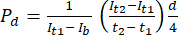
    Equation 1        (1)
    1. Start ImageJ, and open the image acquired at the initial time point.
    2. Set the scale in ImageJ. Navigate to Analyze | Set Scale. Input the known scale and unit of measurement.
    3. Select the rectangle tool and draw a rectangle over the area of the gel where the fluorescence intensity measurement is required.
    4. Navigate to Analyze | Set Measurements and ensure that the Mean gray value is checked.
      NOTE: This option measures the average intensity within the selected area. Other parameters can be selected as needed for the given analysis.
    5. With the area still selected, navigate to Analyze | Measure or simply press M. Wait for a results window to open, showing the mean fluorescence intensity and any other parameters selected.
    6. Take three measurements and calculate the average fluorescence intensity value in a spreadsheet.
    7. Repeat this procedure for the images captured at the subsequent time point t2, as well as those taken before the addition of the dextran solution for calculation of fluorescence intensity at the later time point, to determine the background fluorescence.

Representative Results

The VOP platform, featuring flexibility in size and pattern, was fabricated with a multi-head bioprinting system. Channels, both hollow and capable of perfusion, were seeded with HUVECs to facilitate endothelialization and were subsequently assessed with a permeability assay (Figure 1A). To demonstrate the multiscale manufacturing capability of this method, we printed three distinct configurations: straight, bifurcated, and convoluted (Figure 1B). Through a straightforward fabrication approach, six hollow, perfusable vascular channels embedded within a hydrogel matrix can be produced inside a standard six-well plate. These channels can then be endothelialized with HUVECs (Figure 2A). The cells rapidly attach and proliferate to cover the luminal surface of the vascular channel (Figure 2B). Cells adhered to both the lower and upper luminal surfaces exhibit a uniform distribution inside the lumen (Supplemental Figure S1).

The plate was placed in a humidified incubator for 3 days to allow the silicon ink to cure while ensuring that the sacrificial pattern remained free from desiccation (Figure 3A). To evaluate the flow through these channels, green microbeads were introduced, demonstrating that the channels are effectively perfusable (Supplemental Video S1). The diameter of the channels was varied from 558 ± 38 µm to 1094 ± 45 µm by altering the nozzle size from 22 G to 18 G during sacrificial pattern printing. Additionally, the geometrical configuration of the channels was manipulated by modification of the G-code of the bioprinter (Supplemental File 1) to enable the printing of convoluted and bifurcated patterns (Figure 3B).

Crosslinking duration with UV was optimized to 120 s, which supports effective cell proliferation (Supplemental Figure S2). This crosslinking duration resulted in a more physiologically relevant environment that promotes endothelial cell proliferation, likely due to the balanced mechanical properties and porosity of the hydrogel, facilitating better cell attachment and subsequent proliferation.HUVECs proliferated effectively on the luminal surface and showed a cobblestone-like morphology by day 5 after seeding. The maturation of the endothelium was evaluated with CCK8 assay conducted on days 1, 3, and 5 (Figure 4A,B). The maturation of the endothelium was verified by immunostaining for CD31 5 days post cell seeding, which demonstrated the localization of CD31 at the tight junctions (Figure 4D).

To evaluate the barrier function of the endothelium, we perfused a 70 kDa dextran solution through the channels on day 5 of maturation. For comparison, a control channel without endothelium (bare) was selected. The endothelialized channel exhibited minimal changes in fluorescence within the perivascular gel region over time, thereby suggesting that the endothelium effectively maintained its barrier function. However, the bare channels exhibited an increase in fluorescence in the perivascular gel region, thus indicating higher permeability due to the absence of endothelium (Figure 4C and Figure 4E).

Figure 1
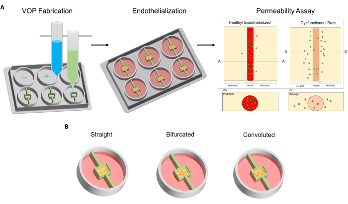
Figure 1: Preparation of printed vascular channels and their configurations. (A) Schematic of fabrication, endothelialization, and permeability assay of printed vascular channels. (B) Schematic of the three configurations demonstrated in this method: straight, bifurcated, and convoluted. Abbreviation: VOPs = vessels on a plate. Please click here to view a larger version of this figure.

Figure 2
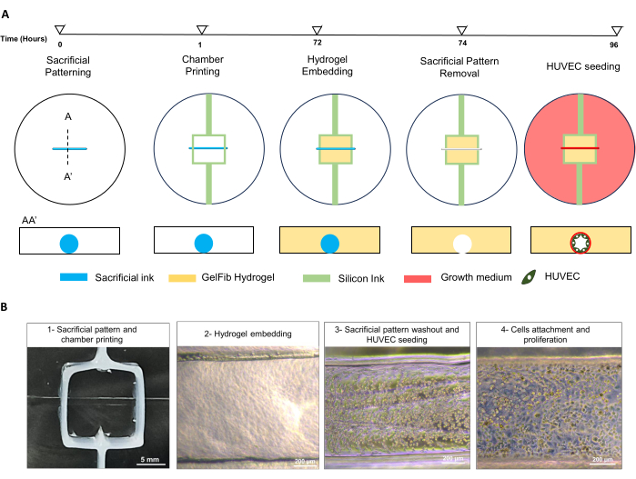
Figure 2: Fabrication timeline for printing the sacrificial pattern and silicon chamber, as well as vascular channel endothelialization. (A) The illustration represents a single well of the well plate and AA' refers to the view along the cross-sectional plane. (B) Representative images of steps involved in the fabrication process. Scale bars = 5 mm (B1), 200 µm (B24). Abbreviations: GelFib = 15% gelatin methacrylate and 1% fibrinogen in 0.05% w/v lithium phenyl-2,4,6-trimethylbenzoylphosphinate solution; HUVECs = Human umbilical vein endothelial cells. Please click here to view a larger version of this figure.

Figure 3
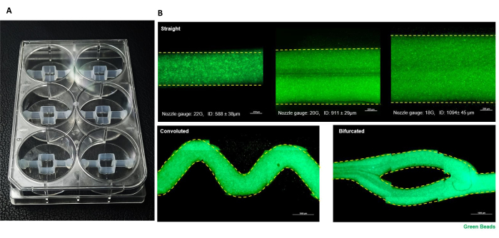
Figure 3: Vessels on a plate. (A) Gross image of vessels on a plate after printing of the sacrificial pattern and silicon chamber. (B) Demonstration of multiscale fabrication of vascular channels with a variety of configurations and sizes, perfused with green microbeads. Scale bars = 200 µm (straight channels), 1,000 µm (convoluted and bifurcated channels). Abbreviations: ID = internal diameter. Please click here to view a larger version of this figure.

Figure 4
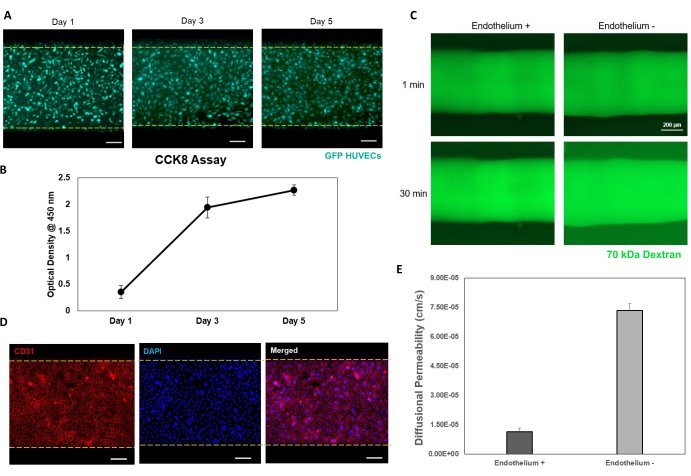
Figure 4: Vascular channels and their endothelial maturation and permeability. (A) Fluorescence microscopic images of vascular channels at days 1, 3, and 5 after seeding with green fluorescent protein-tagged HUVECs, showing the proliferation and cobblestone morphology of HUVECs at day 5. (B) Endothelial maturation was assessed with CCK-8 assay at days 1, 3, and 5 after cell seeding. (C) Permeability assay of endothelialized (endothelium +) and bare (endothelium -) vascular channels. (D) Representative images of CD31 staining illustrate the localization of CD31 at tight junctions on day 5. (E) Quantification of diffusional permeability. Scale bars = 200 µm (A, C, D). Abbreviations: HUVECs = Human umbilical vein endothelial cells; GFP = green fluorescent protein; GFP HUVECs = GFP-tagged HUVECs; CCK-8 = cell counting kit 8; DAPI = 4'6-diamidino-2-phenylindole. Please click here to view a larger version of this figure.

Printing Ink Printing parameters
Nozzle gauge Temperature (°C) Air pressure (kPa) Head speed (mm/min)
Sacrificial ink 18 37 40-48 200
20
22
Silicon ink 22 5 100

Table 1: Printing parameters for the sacrificial and silicon inks.

Supplemental File 1: G-Code script containing the commands for 3D printing the sacrificial pattern and silicon chamber inside a six-well plate. Please click here to download this File.

Supplemental Figure S1: Representative images of the lower and upper luminal surface after cell seeding showing GFP-HUVEC attachment at both lower and upper focal planes. Scale bars = 200 µm. Abbreviations: UU' = upper focal plane; LL' = lower focal plane. Please click here to download this File.

Supplemental Figure S2: GFP-HUVEC proliferation under different durations of crosslinking with UV (405 nm). Scale bars = 200 µm. Abbreviations: HUVECs = Human umbilical vein endothelial cells; GFP = green fluorescent protein; GFP HUVECs = GFP-tagged HUVECs. Please click here to download this File.

Supplemental Video S1: Perfusion with green microbeads showing the effective perfusion through the straight, convoluted, and bifurcated channels. Please click here to download this File.

Supplemental Table S1: Functions of G-code and M-code commands. NOTE: In G-code, X, Y, and Z indicate the coordinates for movement along the X-axis, Y-axis, and Z-axis, respectively. Please click here to download this File.

Discussion

Taking advantage of the precision, automation, and computer-controlled nature of 3D bioprinting technology, we established a streamlined method for fabricating vascular channels in standard six-well plates, which were chosen for their compatibility with commercial microplate readers and microscope imaging setups. The plate's design can accommodate multi-size channels and a sufficient volume of media for the growth of larger channels while decreasing the necessary frequency of media changes. Future adaptations of this design could be adapted to other commercially available standard well plates, thus increasing experimental throughput and decreasing the use of materials.

Microfluidic platforms often use a silicone polymer called PDMS because of its non-toxicity, gas permeability, and high transparency28. However, PDMS's low shape fidelity limits its use in microextrusion-based bioprinting for chip fabrication with high shape fidelity. SE170029, another silicone polymer, offers higher precision in constructing chambers for tissue fabrication, but its high viscosity necessitates larger nozzles and substantial pneumatic pressure. We formulated a blend of SE1700 and PDMS that can be used with smaller nozzles, thereby enabling fabrication in confined areas with high precision and shape fidelity. Other types of polymers, such as Polycaprolactone (PCL) or Polyethylene Vinyl Acetate (PEVA), can also be employed for chamber printing considering their high shape fidelity30.

The optical transparency of GelMA is also crucial31. In contrast to other ECM-based hydrogels – such as collagen, which becomes opaque after crosslinking – GelMA retains transparency, thus allowing for real-time cellular analysis within channels, even as the channel size increases. This aspect provides a major advantage over methods requiring thin sections for observation when the size of the construct is increased32. GelMA's biodegradability facilitates the replacement of the ECM scaffold with new, functional tissue as it disintegrates, thereby providing the necessary space for the growth of newly formed functional tissue33,34. Additionally, its proven low cytotoxicity renders it highly suitable for tissue engineering applications35,36. The excellent mechanical characteristics of GelMA make it a good candidate for applications in vascular tissue engineering37. Its effectiveness in facilitating the endothelialization of vascular conduits with HUVECs has been well-documented38.

The cells utilized for endothelialization in this study, HUVECs, exhibit a high isolation success rate and are an exceptional model for examining a wide range of cardiovascular and metabolic diseases39. However, this approach can be tailored to accommodate different types of endothelial cells, including those derived from arteries or directly from patients. This adaptability enables the creation of patient-specific vascular tissue models, facilitating the evaluation of individual responses to specific drugs.

This protocol has some critical steps for readers to keep in mind. First, plasma treatment is critical for modifying the surface characteristics of the plate, specifically to enhance hydrophilicity, because most commercial well plates are hydrophobic. The plasma treatment introduces polar functional groups on the surface, thus improving the bonding ability with the silicon chamber and hydrogel. Second, temperature control is crucial because the sacrificial ink liquifies at lower temperatures, and the silicon ink requires lower temperatures to prevent premature curing, which can impede ink extrusion through the nozzle. Third, thorough removal of all traces of PF127 is crucial because any residual PF127 can adversely affect the cellular processes, such as by interfering with cell adhesion40. Fourth, during cell culture, if the cells grow to a confluency exceeding 90%, they can experience stress because of competition for space and nutrients. This stress can result in altered cell behavior, decreased cell viability, and modifications to the cellular microenvironment. To maintain cell health and proper proliferation, keeping cultures below 90% confluency is recommended. Fifth, it is important to keep the plate flat inside the incubator before and after inversion to achieve uniform cell adhesion inside the channel and ultimately uniform endothelialization. Finally, maintaining consistent exposure time, excitation laser intensity, and microscope focus is crucial during image acquisition, because variations in these parameters could change the intensity of the emission signal, thus potentially affecting the accuracy of the results.

Our approach allows for the creation of channels in multiple configurations, such as the straight, bifurcated, and convoluted patterns demonstrated herein. This adaptability is essential for replicating the diverse vascular network geometries in the human body and surpasses the capabilities of traditional methods, such as hydrogel casting around a mold or the concentric nozzle-based bioprinting techniques used for tube-like structures30,41,42. However, one limitation of this method is that it does not ensure the circularity of the channels because the sacrificial pattern is laid out on a flat surface.

The advantage of constructing channels in multiple sizes is key to overcoming the limitations of microfluidic platforms, which are often restricted to microchannels. This restriction can be a drawback in conventional biochemical assays. For example, to obtain sufficient material for standard protein expression assays such as western blotting, outputs from several microfluidic devices must be combined. Additionally, when hollow channels are created, the hydrogel must maintain sufficient stiffness to endure the needle removal process. Our approach uses a thermoreversible sacrificial material, which becomes liquid when the temperature is decreased, thus facilitating this process without damaging the integrity of the gel. Moreover, other thermoreversible gelling materials, such as gelatin43, can also be utilized as sacrificial materials in this method.

This approach enables easy customization of tissue structures on the plate, thus providing a promising tool for pharmacological testing in drug discovery. This method can facilitate the screening of drugs by evaluating their effects on vascular permeability-a key factor in developing therapies for diseases associated with vascular dysfunction. Our model can be used to study vascular permeability under specific conditions, such as inflammation, and to develop strategies for vascular normalization, which is relevant for treating various diseases involving abnormal vascular permeability44, advancing the understanding of this process, and developing potential clinical applications45.

To assess vascular permeability, we perfused 70 kDa dextran through the vascular channel. Typically, a healthy vascular endothelium serves as an effective barrier to dextran molecules of this molecular weight46. However, in the presence of inflammation, disruption of the tight junctions occurs, allowing these molecules to leak through, thereby increasing vascular permeability30. Additionally, fluorescence-labeled dextran is utilized to evaluate the distribution of drugs within engineered tissues47. Although bidirectional flow and limited control overflow dynamics within the channel are limitations of this model, we envision that end-users will be able to adapt the system according to their requirements by using customized rockers to control the flow dynamics within the channels. This adaptation may include the implementation of pumpless unidirectional flow48.

In the future, this fabrication method could be scaled up to construct complex tissues. By precisely positioning other types of cells near vascular channels, perfusable, vascularized tissues could be created, thereby overcoming a major challenge in bioprinting volumetric tissues. We also believe that this method could be adapted for simulating other types of hollow, perfusable tissues, such as lymphatic vessels and intestines, in a high-throughput manner for a variety of biomedical applications.

Disclosures

The authors have nothing to disclose.

Acknowledgements

This work was supported by the National Research Foundation of Korea (NRF) grants funded by the Korea government (Ministry of Science and ICT, MSIT) [No. NRF-2019R1C1C1009606; No. 2020R1A5A8018367; and No. RS-2024-00423107]. This research was supported by the Bio and Medical Technology Development Program of the NRF grants funded by the MSIT [No. NRF-2022M3A9E4017151 and No. NRF-2022M3A9E4082654]. This work was supported by the Technology Innovation Program [No. 20015148] and the Alchemist Project [No. 20012378] funded By the Ministry of Trade, Industry and Energy (MOTIE, Korea). This work was also supported by Korea Institute of Planning and Evaluation for Technology in Food, Agriculture and Forestry (IPET) through the Agriculture and Food Convergence Technologies Program for Research Manpower development, funded by Ministry of Agriculture, Food and Rural Affairs (MAFRA) [No. RS-2024-00397026].

Materials

10 mL Serological Pipette SPL SPL 91010
10 mL syringe  Shinchang Medical
15 mL conical tube SPL 50015
3D Bioprinter  T&R Biofab 3DX-Printer
6-well plate  SPL 37206
Biological Safety Cabinets CHC LAB PCHC-777A2-04, 
Brightfield Inverted Microscopes Leica DMi1
Cell Counting Kit (CCK8) GlpBio GK10001
Cell Culture Flask 75T SPL 70075
Corning Matrigel Growth Factor Reduced (GFR) Basement Membrane Matrix, LDEV-free, 10 mL Corning 354230
Distilled water
DMEM/F12 Gibco 11320033
DMSO, Cell Culture Grade Sigma aldrich D2438
Dow-Corning, PDMS-Sylgard 184a Kit DOW DC-184
DOWSIL SE 1700 Clear W/C 1.1 KG Kit  DOW 2924404
D-PBS – 1x Welgene LB001-01
Endothelial Cell Growth Medium MV 2 (Ready to use) Promocell C-22022
Eppendorf Micro pipette(1000,200,100,20,10) eppendorf
Ethyl Alcohol 99.9% Duksan D5
Excel Microsoft
Fibrinogen from bovine plasma Sigma Aldrich F8630-1G
FITC Dextran 70 kDa Sigma Aldrich 46945-100MG-F
Fluorescent beads (1.0 μm, green) Sigma Aldrich L1030-1ML
GelMA-powder (Gelatin methacrylate) 50 g 3D Materials  20JT29
Gibco, Recovery Cell Culture Freezing Medium, 50 mL Gibco
HUVECs (Human Umbillical Vein Endothelial Cells) Promocell
ImageJ software NIH
Incubator Thermo SCIENTIFIC Forma STERI-CYCLE i160 CO2 Incubator
Invitrogen, Live/dead viability/cytotoxicity Kit (for mammalian cells) Thermo Fisher L3224
Lithium Phenyl (2,4,6-trimethylbenzoyl) phosphate powder  Tokoyo Chemical Industry CO. 85073-19-4 
Marienfeld Superior, Counting chamber cover Marienfeld Superior
Marienfeld Superior, Hemocytometer, cell counting chamber Marienfeld Superior HSU-0650030
Microcentrifuge eppendorf Centrifuge 5920 R
NCViewer.com
Nitrogen tank WORTHINGTON INDUSTRIES LS750
Omnicure UV Laser EXCELITAS SERIES 1500
Parafilm M amcor PM-996
Penicillin-Streptomycin Solution (100x) GenDEPOT CA005-010
Planetary Mixer THINKY CORPORATION, japan ARE-310
Plasma treatment machine FEMTO SCIENCE CUTE-1MPR
Pluronic F-127 Sigma aldrich P2443-250G
Pre-made buffer, (P2007-1) 10x PBS Biosesang PR4007-100-00
Reagent storage cabinet ZIO FILTER TECH SC2-30F-1306D1-BC
Real time Live cell Imaging Microscope Carl ZEISS
Refrigerator SAMSUNG RT50K6035SL
ROCKER 2D digital IKA 4003000
Scoop-Spatula CacheBy SL-SCO7001-EA
sigma,Trypsin-EDTA solition, 0.25% Sigma aldrich T4049-100ML
Sodium Dodecyl Sulfate (SDS) Thermo Fisher scientific 151-21-3
Syringe Barrel Tip Cap FISNAR 3051806
Tally counter Control Company  C23-147-050
Tapered Nozzle (18 G) Mushashi TPND-18G-U
Tapered Nozzle (22 G) Mushashi TPND-22G-U
Tapered nozzle 20 G Musashi TPND-20G-U
Thrombin from bovine plasma Sigma Aldrich T7326-1KU
Timer, 4-channel ETL SL.Tim3005
Trypan Blue Solution 0.4% Gibco 15250061
Trypsin Neutralizing Solution Promocell C-41120
UG 24 mL UG ointment jar Yamayu No. 3-53
UG 58 mL UG ointment jar Yamayu No. 3-55
Water Bath DAIHAN Scientific WB-11
Weight machine Sartorius bce2241-1skr

References

  1. O’Connor, C., Brady, E., Zheng, Y., Moore, E., Stevens, K. R. Engineering the multiscale complexity of vascular networks. Nat Rev Mater. 7 (9), 702-716 (2022).
  2. Claesson-Welsh, L., Dejana, E., McDonald, D. M. Permeability of the Endothelial Barrier: Identifying and Reconciling Controversies. Trends Mol Med. 27 (4), 314-331 (2021).
  3. Claesson-Welsh, L. Vascular permeability-the essentials. Ups J Med Sci. 120 (3), (2015).
  4. Wautier, J. -. L., Wautier, M. -. P. Vascular Permeability in Diseases. Int. J. Mol. Sci. 23 (7), (2022).
  5. Higashi, Y., Kihara, Y., Noma, K. Endothelial dysfunction and hypertension in aging. Hypertens Res. 35 (11), (2012).
  6. Gallo, G., Volpe, M., Savoia, C. Endothelial dysfunction in hypertension: current concepts and clinical implications. Front Med (Lausanne). 8, 798958 (2022).
  7. Park, W., Lee, J. -. S., Gao, G., Kim, B. S., Cho, D. -. W. 3D bioprinted multilayered cerebrovascular conduits to study cancer extravasation mechanism related with vascular geometry. Nat Commun. 14 (1), 7696 (2023).
  8. Sun, H. -. J., Wu, Z. -. Y., Nie, X. -. W., Bian, J. -. S. Role of endothelial dysfunction in cardiovascular diseases: the link between inflammation and hydrogen sulfide. Front Pharmacol. 10, 1568 (2020).
  9. Yuan, Y., Sun, J., Dong, Q., Cui, M. Blood-brain barrier endothelial cells in neurodegenerative diseases: Signals from the "barrier.". Front Neurosci. 17, 1047778 (2023).
  10. Hadi, H. A., Suwaidi, J. A. Endothelial dysfunction in diabetes mellitus. Vasc Health Risk Manag. 3 (6), 853-876 (2007).
  11. De Vriese, A. S., Verbeuren, T. J., Van de Voorde, J., Lameire, N. H., Vanhoutte, P. M. Endothelial dysfunction in diabetes. Br J Pharmacol. 130 (5), 963-974 (2000).
  12. Wang, K., et al. Inflammatory environment promotes the adhesion of tumor cells to brain microvascular endothelial cells. Front Oncol. 11, 691771 (2021).
  13. Tiwary, S., et al. Metastatic brain tumors disrupt the blood-brain barrier and alter lipid metabolism by inhibiting expression of the endothelial cell fatty acid transporter Mfsd2a. Sci Rep. 8 (1), 8267 (2018).
  14. Chauhan, V. P., Stylianopoulos, T., Boucher, Y., Jain, R. K. Delivery of molecular and nanoscale medicine to tumors: transport barriers and strategies. Annu Rev Chem Biomol Eng. 2 (1), 281-298 (2011).
  15. Van Norman, G. A. Limitations of animal studies for predicting toxicity in clinical trials: Is it time to rethink our current approach. JACC Basic Transl Sci. 4 (7), 845-854 (2019).
  16. Morgan, S. J., et al. Use of animal models of human disease for nonclinical safety assessment of novel pharmaceuticals. Toxicol Pathol. 41 (3), 508-518 (2013).
  17. Can Pfizer deliver. MIT Technology Review Available from: https://www.technologyreview.com/2004/02/01/233321/can-pfizer-deliver/ (2004)
  18. Raasch, M., et al. Microfluidically supported biochip design for culture of endothelial cell layers with improved perfusion conditions. Biofabrication. 7 (1), 015013 (2015).
  19. Xu, Z., et al. Design and construction of a multi-organ microfluidic chip mimicking the in vivo microenvironment of lung cancer metastasis. ACS Appl Mater Interfaces. 8 (39), 25840-25847 (2016).
  20. Strobel, H. A., et al. Assembly of tissue-engineered blood vessels with spatially controlled heterogeneities. Tissue Eng Part A. 24 (19-20), 1492-1503 (2018).
  21. Atchison, L., Zhang, H., Cao, K., Truskey, G. A. A Tissue engineered blood vessel model of Hutchinson-Gilford Progeria Syndrome using human iPSC-derived smooth muscle sells. Sci Rep. 7 (1), 8168 (2017).
  22. Ronaldson-Bouchard, K., Vunjak-Novakovic, G. Organs-on-a-Chip: A fast track for engineered human tissues in drug development. Cell Stem Cell. 22 (3), 310-324 (2018).
  23. Gold, K. A., et al. 3D bioprinted multicellular vascular models. Adv Healthc Mater. 10 (21), 2101141 (2021).
  24. Tabriz, A. G., Hermida, M. A., Leslie, N. R., Shu, W. Three-dimensional bioprinting of complex cell laden alginate hydrogel structures. Biofabrication. 7 (4), 045012 (2015).
  25. Gao, G., et al. Tissue engineered bio-blood-vessels constructed using a tissue-specific bioink and 3D coaxial cell printing technique: a novel therapy for ischemic disease. Adv. Funct. Mater. 27 (33), 1700798 (2017).
  26. Cho, W. -. W., Ahn, M., Kim, B. S., Cho, D. -. W. Blood-lymphatic integrated system with heterogeneous melanoma spheroids via in-bath three-dimensional bioprinting for modelling of combinational targeted therapy. Adv Sci (Weinh). 9 (29), 2202093 (2022).
  27. Kolesky, D. B., et al. 3D bioprinting of vascularized, heterogeneous cell-laden tissue constructs. Adv Mater. 26 (19), 3124-3130 (2014).
  28. Polacheck, W. J., Kutys, M. L., Tefft, J. B., Chen, C. S. Microfabricated blood vessels for modeling the vascular transport barrier. Nat Protoc. 14 (5), 1425-1454 (2019).
  29. Li, H., et al. Expanding sacrificially printed microfluidic channel-embedded paper devices for construction of volumetric tissue models in vitro. Biofabrication. 12 (4), 045027 (2020).
  30. Gao, G., Park, J. Y., Kim, B. S., Jang, J., Cho, D. Coaxial cell printing of freestanding, perfusable, and functional in vitro vascular models for recapitulation of native vascular endothelium pathophysiology. Adv Healthc Mater. 7 (23), 1801102 (2018).
  31. Farasatkia, A., Kharaziha, M., Ashrafizadeh, F., Salehi, S. Transparent silk/gelatin methacrylate (GelMA) fibrillar film for corneal regeneration. Mater Sci Eng C Mater Biol Appl. 120, 111744 (2021).
  32. Duong, V. T., et al. Double-layered blood vessels over 3 mm in diameter extruded by the inverse-gravity technique. Biofabrication. 15 (4), 045022 (2023).
  33. Luo, L., et al. Application of bioactive hydrogels combined with dental pulp stem cells for the repair of large gap peripheral nerve injuries. Bioact Mater. 6 (3), 638-654 (2021).
  34. Zhu, M., et al. Gelatin methacryloyl and its hydrogels with an exceptional degree of controllability and batch-to-batch consistency. Sci Rep. 9 (1), 6863 (2019).
  35. Wang, Y., et al. Development of a photo-crosslinking, biodegradable GelMA/PEGDA hydrogel for guided bone regeneration materials. Materials. 11 (8), 1345 (2018).
  36. Han, Y., et al. Biomimetic injectable hydrogel microspheres with enhanced lubrication and controllable drug release for the treatment of osteoarthritis. Bioact Mater. 6 (10), 3596-3607 (2021).
  37. Bupphathong, S., et al. Gelatin methacrylate hydrogel for tissue engineering applications-a review on material modifications. Pharmaceuticals. 15 (2), 171 (2022).
  38. Wu, Z., et al. Microfluidic printing of tunable hollow microfibers for vascular tissue engineering. Adv Mater Technol. 6 (8), 2000683 (2021).
  39. Medina-Leyte, D. J., Domínguez-Pérez, M., Mercado, I., Villarreal-Molina, M. T., Jacobo-Albavera, L. Use of human umbilical vein endothelial cells (HUVEC) as a model to study cardiovascular disease: a review. Appl. Sci. 10 (3), 938 (2020).
  40. Khattak, S. F., Bhatia, S. R., Roberts, S. C. Pluronic F127 as a cell encapsulation material: utilization of membrane-stabilizing agents. Tissue Eng. 11 (5-6), 974-983 (2005).
  41. Jia, W., et al. Direct 3D bioprinting of perfusable vascular constructs using a blend bioink. Biomaterials. 106, 58-68 (2016).
  42. Kim, S. -. J., et al. Bioprinting methods for fabricating in vitro tubular blood vessel models. Cyborg Bionic Syst. 4, 0043 (2023).
  43. Maji, S., Lee, M., Lee, J., Lee, J., Lee, H. Development of lumen-based perfusable 3D liver in vitro model using single-step bioprinting with composite bioinks. Mater Today Bio. 21, 100723 (2023).
  44. Pauty, J., et al. A vascular permeability assay using an in vitro human microvessel model mimicking the inflammatory condition. Nanotheranostics. 1 (1), 103-113 (2017).
  45. van Duinen, V., et al. 96 perfusable blood vessels to study vascular permeability in vitro. Sci Rep. 7 (1), 18071 (2017).
  46. Pink, D. B. S., Schulte, W., Parseghian, M. H., Zijlstra, A., Lewis, J. D. Real-time visualization and quantitation of vascular permeability in vivo: implications for drug delivery. PLoS ONE. 7 (3), e33760 (2012).
  47. Filippi, M., et al. Perfusable biohybrid designs for bioprinted skeletal muscle tissue. AAdv Healthc Mater. 12 (18), 2300151 (2023).
  48. Zhang, F., Lin, D. S. Y., Rajasekar, S., Sotra, A., Zhang, B. Pump-less platform enables long-term recirculating perfusion of 3D printed tubular tissues. Adv Healthc Mater. 12 (27), 2300423 (2023).
This article has been published
Video Coming Soon
Keep me updated:

.

Cite This Article
Ahmad, A., Zobaida Akter, M., Kim, S., Choi, Y., Yi, H. High-Throughput Bioprinting Method for Modeling Vascular Permeability in Standard Six-well Plates with Size and Pattern Flexibility. J. Vis. Exp. (210), e66676, doi:10.3791/66676 (2024).

View Video