We demonstrate the transmission of multiple independent signals through a multimode fiber using wavefront shaping employing a single spatial light modulator. By modulating the wavefront for each signal individually, spatially separated foci are transmitted. Potential applications are multiplexed data transfer in communications engineering and endoscopic light delivery in biophotonics.
The transmission of multiple independent optical signals through a multimode fiber is accomplished using wavefront shaping in order to compensate for the light distortion during the propagation within the fiber. Our methodology is based on digital optical phase conjugation employing only a single spatial light modulator, where the optical wavefront is individually modulated at different regions of the modulator, one region per light signal. Digital optical phase conjugation approaches are considered to be faster than other wavefront shaping approaches, where (for example) a complete determination of the wave propagation behavior of the fiber is performed. In contrast, the presented approach is time-efficient since it only requires one calibration per light signal. The proposed method is potentially appropriate for spatial division multiplexing in communications engineering. Further application fields are endoscopic light delivery in biophotonics, especially in optogenetics, where single cells in biological tissue have to be selectively illuminated with high spatial and temporal resolution.
The transmission of multiple light signals through a multimode fiber (MMF) is evident in communications engineering1 and biophotonics2. In communications engineering, space-division multiplexing (SDM) is believed to be a viable solution in order to enhance the transmission capacity of optical fibers for future data transfer applications benefiting from a higher utilization of the limited space, compared to multiple single-mode fibers3. In biophotonics, biological samples are manipulated by light transmitting through an MMF endoscope4. For example, the independent optical control of individual neurons using MMF endoscopes is of interest for optogenetics in order to study neuronal networks in the brain5. However, the light projected onto the MMF input facet is subject to distortion due to mode mixing and dispersion during propagation to the output facet of the MMF. As a result, the light propagation is altered, which makes signal transmission challenging.
Wavefront shaping methods6,7 are applied in scattering media using spatial light modulators (SLM) and enable the compensation for the distortion due to scattering during light propagation8. There are iterative approaches that optimize the output using an optical feedback9. These approaches are rather time consuming because of the necessity for numerous iterations and the high degree of freedom, corresponding to a large number of modulator elements. Another approach is to completely determine the distortion within the MMF described by its transmission matrix10. If the number of modes to be transmitted is large, this will be time consuming as well. In contrast, digital optical phase conjugation (DOPC) is considered to be fast and advantageous here, since only few focal spots have to be generated at the output facet of the MMF. Phase conjugation approaches have also been demonstrated for focusing or imaging through biological tissue12,13,14.
So far, DOPC was employed for a single time signal only15,16, and was applied for the transmission of light through an MMF17. A DOPC approach for multiple independent signals has not been accomplished. We have developed an enhanced DOPC method providing the independent transmission of multiple light signals using individual wavefront shaping for each signal employing a single phase-only SLM18. To this aim, the SLM is segmented into regions, one for each signal to be transmitted. The proposed experimental setup is depicted in Figure 1, where a calibration is performed in a) before the actual transmission happens in b).
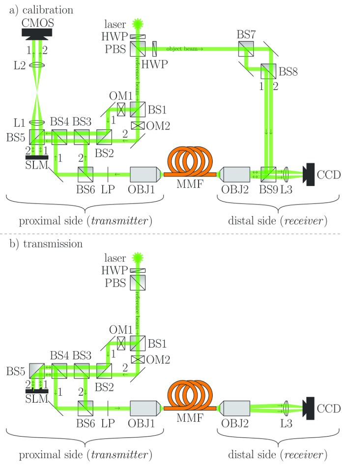
Figure 1: Experimental setup. BS = beam splitter, CCD = charge-coupled device, OM = optical modulator, CMOS = complementary metal-oxide semiconductor, HWP = half wave plate, L = lens, LP = linear polarizer, MMF = multimode fiber, OBJ = microscope objective, PBS = polarizing beam splitter, SLM = spatial light modulator (phase only) — only relevant beams for (a) the calibration and (b) the transmission are depicted Please click here to view a larger version of this figure.
1. Assembling the Experimental Setup
2. Calibrating the System
3. Transmitting the Signals
Typical output signals at the distal side of the 2 m long fiber are depicted in Figure 2. Note that the desired focal spot (peak) is accompanied by an undesired speckle pattern (background), which is due to imperfection of the DOPC as a matter of principle. The corresponding peak-to-background ratio (PBR) amounts to 53 (solely signal 1 is 'on'), 36 (solely signal 2 is 'on') and 20 (both signals 1 and 2 are 'on') here, respectively. The PBR can be increased when a fiber that supports a larger number of modes (currently: 1710) is used.
Due to the finite PBR, a crosstalk results between the output signals, which is visualized in Figure 3. The crosstalk between to periodic signals with the frequencies f1 and f2 amounts to -24 dB (from signal 2 to signal 1) and -29 dB (from signal 1 to signal 2).
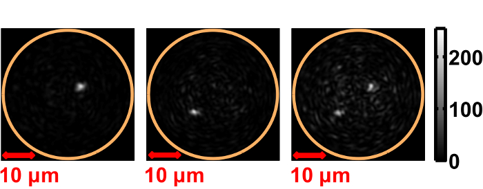
Figure 2: Image of distal fiber end, transmission of output signal 1 (left), signal 2 (center) and both signal 1 and signal 2 (right). Intensity [a. u.] Please click here to view a larger version of this figure.
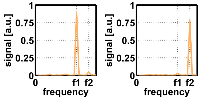
Figure 3: Temporal frequency spectrum of the transmitted output signal 1 (left) and 2 (right). Amplitude [a. u.] Please click here to view a larger version of this figure.
The assembling of the experimental setup (step 1 in the protocol) requires a thorough alignment of the optical components with respect to each other. The most important aspect is the rectangular incidence of the reference beams onto the SLM in order to ensure a high PBR.
In order to enhance the setup to more than two transmitted signals, additional beam splitters could be used. As an alternative, a fiber-based implementation would be more compact and robust allowing the system to be portable for in situ investigations in biophotonics. If a single-side access is possible only, model-based calibration solutions20 need to be accomplished as a future step. The more signals are transmitted, the more modes will be required so more pixels on both the SLM and the CMOS camera will have to be involved for achieving a PBR. Moreover, the number of pixels should be larger than or equal to the number of modes. In addition, the pixel size of the SLM should be twice the size of the smallest speckle diameter at the proximal side. It is further recommended that the SLM has a bit depth of at least four bit. The pixel number of the camera denoted with CMOS should exceed the number of the SLM pixels. However, instead of the CMOS camera any other detector type may be employed, e.g. CCD. The same holds for the camera denoted with CCD.
One limitation of the proposed method is that the light source requires a large coherence length (low spectral bandwidth) to assure interference in the hologram needed for the phase measurement. In addition, the system must be stable, i.e. no changes of the fiber or the optical setup between the calibration and the transmission are tolerable that are faster than the duration of the calibration, which is currently below 1 s. For long fibers and high signal frequencies, the group velocity dispersion of the different fiber modes has to be taken into account and may deteriorate the signal. To compensate for that, gradient-index fibers or the correction of spatiotemporal distortions21 may be used.
In contrast to previous phase conjugation approaches, our proposed SDM method can be used in applications, where independent light signals have to be transmitted. Phase conjugation methods are advantageous regarding time performance, compared to iterative approaches or complete matrix determination.
One further potential application field may be endoscopic light delivery, for instance at optical traps or in optogenetics. For optogenetics, our method is advantageous regarding the selective illumination of single neurons in order to analyze the behavior of the brain and better understand neurodegenerative diseases.
The authors have nothing to disclose.
The financial support by DFG (German research foundation, project CZ 55/30-1) for parts of this work is gratefully acknowledged.
spatial light modulator | Holoeye | PLUTO‐VIS‐016 | |
CMOS camera | Mikrotron | MC4082 | |
diode‐pumped solid state laser | Laser Quantum | torus 532 | |
CCD camera | IDS | U3‐3482LE‐M | CMOS camera; suitable as well |
lens 1 | Qioptiq | G063204000 | |
lens 2 | Qioptiq | G063203000 | |
lens 3 | Thorlabs | AC508‐180‐A‐ML | |
multimode fiber | Thorlabs | M14L02 | |
beam splitters | Thorlabs | BS013 | 9x |
polarizing beam splitters | Thorlabs | PBS251 | |
mirrors | Thorlabs | PF10‐03‐P01 | 5x |
microscope objectives | Thorlabs | RMS20X | 2x |
half wave plates | Thorlabs | WPH10M‐532 | 2x |
linear polarizer | Thorlabs | LPVISB050‐MP2 | |
optical modulators | Thorlabs | MC2000B‐EC | 2x |
linear and rotation stage for CMOS camera | Thorlabs | XYR1/M | |
fiber connector | Thorlabs | S120‐SMA | 2x |
reducing ring for microscope objectives | Qioptiq | G061621000 | 2x |
xy adjustment for objective adapters | Qioptiq | G061025000 | 2x |
z translation mount for fiber adapter | Thorlabs | SM1Z | 2x |
rods for fiber alignment to objectives | Qioptiq | G061210000 | 8x |
mounts for lenses 1 and 2 plus two phantom mounts | Qioptiq | G061047000 | 4x |
rail carriers for objective and lens mounts | Qioptiq | G061372000 | 6x |
rail for rail carriers | Qioptiq | G061359000 | 2x |
adapter for CCD camera to 1 post | in-house | ||
adapter for laser to 4 posts | in-house | ||
mount for lens 3 | Thorlabs | LMR2/M | |
mounts for half wave plates | Thorlabs | RSP1D/M | 2 |
mounts for mirrors | Thorlabs | KM100 | 5x |
mount for linear polarizer | Thorlabs | RSP05/M | |
mounts for beam splitters and SLM | Thorlabs | KM100PM/M | 11x |
clamping arms for beam splitters and SLM | Thorlabs | PM4/M | 11x |
posts for mounts, rail carriers and adapters | Thorlabs | TR75/M | 29x |
holders for posts | Thorlabs | PH50/M | 29x |
pedestals for holders | Thorlabs | BE1/M | 29x |
clamping forks for pedestals | Thorlabs | CF125 | 29x |