A reverse engineering system is employed to record and obtain detailed and comprehensive geometry data of vertebral endplates. Parametric models of vertebral endplate are then developed, which are beneficial to designing personalized spinal implants, making clinical diagnoses, and developing accurate finite element models.
Detailed and comprehensive geometric data of vertebrae endplates is important and necessary to improve the fidelity of finite element models of the spine, design and ameliorate spinal implants, and understand degenerative changes and biomechanics. In this protocol, a high-speed and highly accurate scanner is employed to convert morphology data of endplate surfaces into a digital point cloud. In the software system, the point cloud is further processed and reconstructed into three dimensions. Then, a measurement protocol is performed, involving a 3D coordinate system defined to make each point a 3D coordinate, three sagittal and three frontal surface curves that are symmetrically fitted on the endplate surface, and 11 equidistant points that are selected in each curve. Measurement and spatial analyses are finally performed to obtain geometric data of the endplates. Parametric equations representing the morphology of curves and surfaces are fitted based on the characteristic points. The suggested protocol, which is modular, provides an accurate and reproducible method to obtain geometric data of vertebral endplates and may assist in more sophisticated morphological studies in the future. It will also contribute to designing personalized spinal implants, planning surgical acts, making clinical diagnoses, and developing accurate finite element models.
A vertebral endplate is the superior or inferior shell of the vertebral body and serves as a mechanical interface to transfer stress between the disc and vertebral body1. It consists of the epiphyseal rim, which is a strong and solid bony labrum surrounding the outer rim of the vertebral body, and the central endplate, which is thin and porous2.
The spine is subject to a wide array of degenerative, traumatic, and neoplastic disorders, which may warrant surgical intervention. Recently, spinal devices such as artificial discs and cages have been widely used. Accurate and detailed morphometric parameters of endplates are necessary for the design and amelioration of spinal implants with effective prosthesis-vertebra contact and bone ingrowth potential3. Furthermore, information on the exact shape and geometry of vertebral endplates is important for understanding the biomechanics. Although the finite element modeling allows for simulation of the real vertebrae and has been widely used to study physiological responses of the spine to various loading conditions4, this technique is patient-specific and not generalizable to all vertebrae. It has been suggested that the intrinsic variability of vertebrae geometry among the general population should be considered when developing the finite element model5. Therefore, the geometric parameters of endplates are conducive to the mesh generation and fidelity enhancement in finite element modeling.
Although the importance of the matching of endplate geometry and implant surface has been discussed in previous studies6,7,8, data on the morphology of vertebral endplates is scarce. Most previous studies have failed to reveal the 3D nature of the endplate9,10,11. A spatial analysis is required to better and fully depict endplate morphology12,13,14. In addition, most studies have employed lower precision measurement techniques10,15,16. Moreover, significant magnification has been reported when geometry parameters are measured by employing radiography or computed tomography (CT)17,18. Though magnetic resonance imaging (MRI) is considered non-invasive, it is less accurate in defining the precise margins of osseous structures11. Due to a lack of a standardized measurement protocol, there are large differences among existing geometric data.
In recent years, reverse engineering, which can digitize the existing physical parts into computerized solid models, has been increasingly applied to the field of medicine. The technique makes it feasible to develop an accurate representation of the anatomical character of sophisticated vertebrae surfaces. The reverse engineering system includes two subsystems: the instrumentation system and software system. The instrumentation system adopted in this protocol has a non-contact optical 3D range flatbed scanner, which is high-speed and highly accurate (precision 0.02 mm, 1,628 x 1,236 pixels). The scanner can efficiently (input time 3 s) capture surface morphology information of the target object and convert it into digital point cloud. The software system (i.e., reverse engineering software) is a computer application for point cloud data processing (see Table of Materials), 3D surface model reconstruction, free curve and surface editing, and data processing (see Table of Materials).
The purposes of the present report are to (1) devise a measurement protocol and algorithm to obtain quantitative parameters of vertebral endplates based on a reverse engineering technique, (2) develop a mathematical model that allows for a realistic representation of vertebral endplates without digitizing too many landmarks. These methods will be beneficial to surgical act planning and finite element modeling.
This study was approved by the health research ethics board of the authors’ institute. As cervical vertebral bones have more intricate shapes19, the protocol uses the cervical vertebrae as an illustration to facilitate relevant research.
1. Preparation of materials, scanning, and image processing
2. Quantification of 3D morphology of the endplate
3. Development of endplate surface mathematical model
4. Acquisition of geometric data based on parametric equation
5. Representation of the endplate based on parametric equation
Using the highly accurate optical 3D range flatbed scanner, the endplates were converted into more than 45,000 digital points, which adequately characterize the morphology (Figure 2A,B).
In the measurement protocol, the spatial analysis of endplate surfaces was conducted. Representative curves were fitted and quantified on the surface to characterize morphology (Figure 4B). The linear parameters were measured by calculating the distance between two endpoints. Measurements obtained include the concavity depth and concavity apex location in mid-sagittal plane, in addition to those of the whole endplate concavity and any specific section (Figure 5B). The components of endplates, epiphyseal rim, and central endplate were separated (Figure 5C), and their lengths and areas were obtained conveniently.
A total of 138 cervical vertebral endplates were digitized and analyzed, and the mathematical model of the endplate was established. The protocol sets the sums of squared error below 0.01, and it was concluded that using the four-order polynomial function could achieve satisfaction.
The parametric equation of each curve was deduced based on the coordinates of 11 points: f(x) = P1*x^4 + P2*x^3 + P3*x^2 + P4*x + P5. P1, P2, P3, P4 and P5 were the parameters, the exact values of which are shown in Table 1.
The parametric equation representing the morphological characteristics of endplate surface is:
F(x, y) = P00 + P10*x + P01*y + P20*x^2 + P11*x*y + P02*y^2 + P30*x^3 + P21*x^2*y + P12*x*y^2 + P03*y^3 + P40*x^4 + P31*x^3*y + P22*x^2*y^2 + P13*x*y^3 + P04*y^4
Where: PXYs are the parameters, which were deduced from the pre-measured coordinates of 66 points (Table 2).
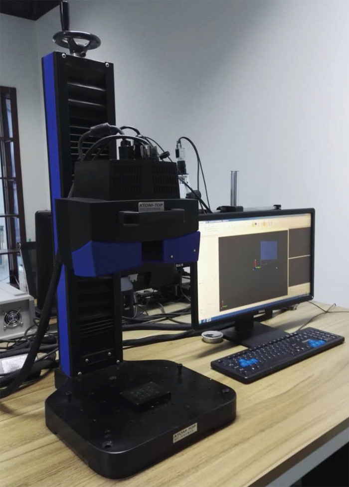
Figure 1: The non-contact optical 3D range flatbed scanner. The scanner, which is based on heterodyne multifrequency phase shift 3D optical measurement technology, includes optical measurement (integrating around two cameras and a projector) and control devices. Precision of this instrument is 0.02 mm, and pixels are 1628 x 1236. The scanner can efficiently (input time 3 s) digitize the surface geometry of a target object. Please click here to view a larger version of this figure.
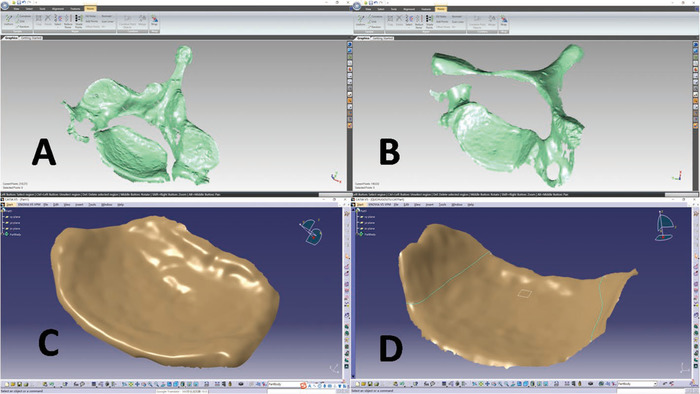
Figure 2: The point cloud of vertebral surface and 3D reconstruction of endplate. (A) and (B) are the inferior and superior surfaces of a cervical vertebra generated by the software specially used for processing point clouds, respectively. (C) and (D) are the 3D reconstruction of the inferior and superior endplates generated by the software specially used for 3D reconstruction and data processing, respectively. The posterior elements and osteophytes are removed from the vertebrae, leaving only the endplate. The best-fit plane is defined through the anterior-most and posterior-most points of the bilateral uncinate processes, and the two curves formed by the best-fit plane and endplate are the boundaries of the uncovertebral joint and caudal endplate. Please click here to view a larger version of this figure.
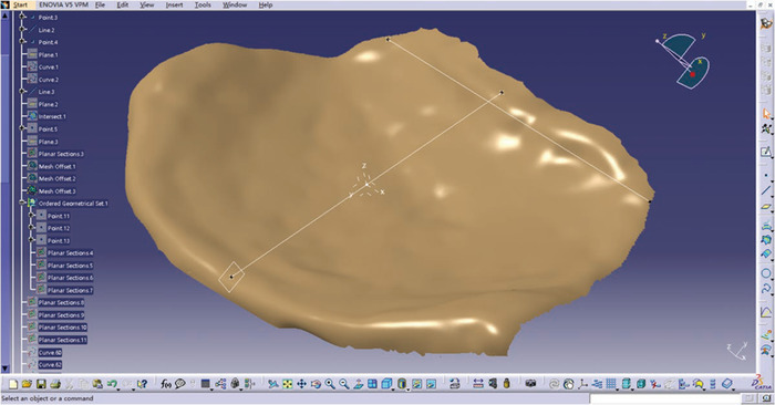
Figure 3: Definition of the endplate 3D coordinate system. Marking of three anatomic landmarks on the epiphyseal rim: the first two are the left and right endpoints of the endplate trailing edge, respectively; the third is the anterior median point. The posterior frontal line is formed by the two trailing edge endpoints, which define the mid-sagittal plane with the anterior median point. The posterior median point is determined by the mid-sagittal plane and posterior epiphyseal rim, which form the mid-sagittal diameter with the anterior median point. The origin is the midpoint of the mid-sagittal diameter. The y-axis is determined by mid-sagittal diameter and pointing forward. The x-axis is the line parallel to the posterior frontal line. The z-axis is normal to the x-y plane. Please click here to view a larger version of this figure.
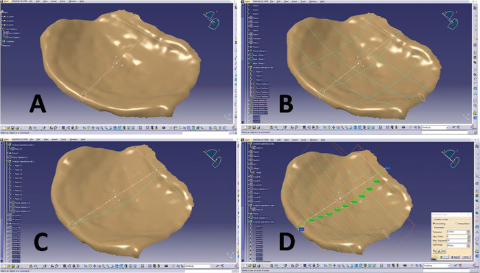
Figure 4: The steps of fitting characteristic curves and points on endplate surface. (A) Divide the mid-sagittal diameter and the mid-frontal diameter equally into four parts. (B) Go through every equidistant point, and choose six surface curves symmetrically, three of which are the intersection curves of the frontal plane and the endplate surface, and the other three in the sagittal plane. (C) Divide the mid-sagittal diameter equally into 10 parts. (D) Going through each equidistant point, the frontal planes and mid-sagittal curve form nine intersections, resulting in a sum of 11 points, together with the two endpoints. Please click here to view a larger version of this figure.
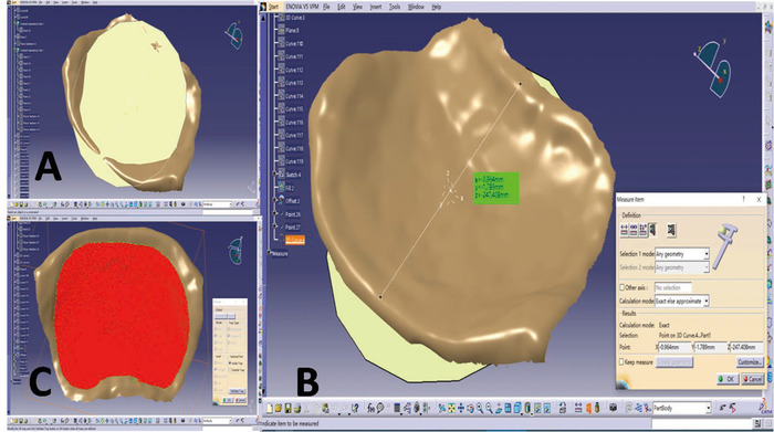
Figure 5: Measurement of endplate concavity depth and surface area. (A) Create a plane parallel to the x-y plane. (B) Offset the plane until it is tangent to the most concave point, and the endplate concavity depth is the perpendicular distance between the most concave point and x-y plane. (C) Draw a line along the inner margins of the epiphyseal ring to partition the endplate into the central endplate and epiphyseal rim. Please click here to view a larger version of this figure.
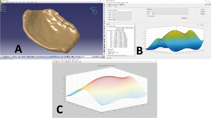
Figure 6: The 3D reconstruction and representations of an inferior endplate. (A) The 3D reconstruction of the inferior endplate surface generated by the software specially used for 3D reconstruction and data processing. (B) and (C) are the representations of the inferior endplate generated by the data analysis and visualization software. Please click here to view a larger version of this figure.
Endplate Level | Curve | Parameters | ||||
P1 | P2 | P3 | P4 | P5 | ||
C6 superior | FAC | 0 | 0 | -0.0128 | -0.0028 | 0.02523 |
FMC | 0 | 0 | -0.0199 | 0.00074 | 0.3693 | |
FPC | 0 | 0 | -0.0329 | 0.00739 | 0.5323 | |
SLC | 0 | 0.00176 | -0.0113 | -0.0419 | -0.0419 | |
SMC | 0.00011 | 0.00232 | -0.016 | -0.0986 | 0.4712 | |
SRC | 0 | 0.00179 | -0.0096 | 0.04451 | -0.0394 | |
C6 inferior | FAC | 0 | -0.0001 | -0.0225 | 0.00594 | 1.223 |
FMC | 0 | 0 | -0.016 | -0.0082 | 1.729 | |
FPC | 0 | 0 | -0.0033 | -0.0033 | 1.404 | |
SLC | 0.00012 | 0.00087 | -0.0347 | -0.0962 | 1.448 | |
SMC | 0.00025 | 0.00064 | -0.0495 | -0.0331 | 1.846 | |
SRC | 0 | 0.00079 | -0.0295 | -0.0828 | 1.362 |
Table 1: The parameters of equation to represent the curve of endplate surface. Only the data of the sixth cervical vertebral endplate is listed. Px = the parameters of the equation. On each end plate, six surface curves were symmetrically chosen; three of these were in the frontal plane and termed the anterior curve (FAC), middle curve (FMC), and posterior curve (FPC); the other three in the sagittal plane were termed the left curve (SLC), middle curve (SMC), and right curve (SRC). Parameters with an absolute value of less than 0.0001 are represented as 0 here.
parameters | C3 inf | C4 sup | C4 inf | C5 sup | C5 inf | C6 sup | C6 inf | C7 sup |
p00 | 1.989 | 0.4187 | 2.004 | 0.3383 | 1.913 | 0.4276 | 1.779 | 0.5674 |
p10 | -0.0022 | -0.0043 | 0.00542 | -0.0208 | -0.0111 | 0.0012 | -0.0043 | -0.0052 |
p01 | -0.0356 | -0.0868 | -0.0537 | -0.0826 | -0.0257 | -0.098 | -0.0407 | -0.0642 |
p20 | 0.01286 | -0.0252 | -0.0146 | -0.0299 | -0.0253 | -0.0264 | -0.0175 | -0.0088 |
p11 | 0.00092 | 0.00071 | -0.0009 | 0.00018 | -0.0002 | -0.0012 | 0.00117 | 0.00021 |
p02 | -0.0529 | -0.0151 | -0.0525 | -0.012 | -0.0418 | -0.0142 | -0.0396 | -0.0134 |
p30 | 0 | -0.0001 | 0.00013 | 0.00024 | 0.00017 | 0 | 0 | 0 |
p21 | -0.0011 | 0.00299 | -0.0012 | 0.00363 | -0.0021 | 0.00306 | -0.0019 | 0.00194 |
p12 | 0 | 0.00048 | -0.0004 | 0.00033 | 0.00014 | 0 | -0.0001 | 0 |
p03 | 0.00062 | 0.00204 | 0.00089 | 0.00206 | 0.00046 | 0.00208 | 0.00077 | 0.00115 |
p40 | 0.0002 | 0 | 0.0002 | 0 | 0.00024 | 0 | 0 | 0 |
p31 | 0 | 0 | 0 | 0 | 0 | 0 | 0 | 0 |
p22 | 0.00017 | 0.00013 | 0 | 0.00015 | 0.00015 | 0.00017 | 0.00032 | 0 |
p13 | 0 | 0 | 0 | 0 | 0 | 0 | 0 | 0 |
p04 | 0.00023 | 0.00013 | 0.00024 | 0 | 0 | 0 | 0 | 0 |
Table 2: The parameters of parametric equation representing the morphology of endplate surface. Px = the parameters of the equation; inf = inferior endplate; sup = superior endplate. Parameters with an absolute value of less than 0.0001 are represented as 0 here. This table has been modified from a previous publication3.
Measurements | Intratest reliability | Measurements | RE vs Caliper | ||
APD | First-remeasurement | 15.76±1.3 | APD | RE | 16.47±1.31 |
Remeasurement | 15.86±1.61 | Caliper | 16.26±1.27 | ||
ICC | 0.85 | Cronbach alpha | 0.99 | ||
CMD | First-remeasurement | 19.71±2.47 | CMD | RE | 20.7±3.05 |
Remeasurement | 19.41±2.43 | Caliper | 20.45±3.21 | ||
ICC | 0.96 | Cronbach alpha | 0.99 |
Table 3: Reliability of measurements. Data were mean ± standard deviation (mm). ICC = intra-class correlation coefficient; APD = antero-posterior diameter; CMD = center mediolateral diameter; RE = the reverse engineering system. This table has been modified from a previous publication.3
Measurements value | N | Z coordinate value | T | P | R |
Original points | 15 | 1.75±0.87 | 0.26 | 0.8 | 0.98 |
Comparison points | 15 | 1.74±0.91 |
Table 4: The validity of the geometric model representing the endplate morphology. Data are represented as mean ± standard deviation (mm). The original points are 15 randomly selected points on the original 3D reconstruction image. Comparison points = corresponding points auto-generated from parametric equations; R = correlation coefficient.
Reverse engineering has been increasingly and successfully applied to the field of medicine, such as cranioplasty20, oral21, and maxillofacial implants21. Reverse engineering measurements, namely product surface digitization, refers to the conversion of surface information into point cloud data employing specific measuring equipment and methods. On the basis of such data, complex surface modeling, evaluation, improvements, and manufacturing can be performed. Digital measurement and data processing are a basic and key technology used in reverse engineering.
In this protocol, accurate and detailed morphology information of vertebral endplates are recorded using a non-contact optical 3D range scanning system, which is based on heterodyne multifrequency, phase-shift, 3D optical measurement technology. The scanner is primarily made of control devices and an optical measurement integrating two cameras and a projector. Compared with other measuring instruments, the scanner is highly accurate and efficient and avoids point-by-point scanning. When capturing point-cloud data, the scanning head is usually not in contact with the object, such that there are no deformation effects. The reliability, validity, and precision of the scanner for recording surface morphology have been well-established2,3,22. The replicability of these measurements have been verified.
To verify the accuracy of measurements taken by the reverse engineering system, 20 endplates were measured using a digital caliper and evaluated using Cronbach alpha. For intra-test reliability, 16 endplates were randomly selected from the 138 vertebral endplates and measured twice at 2 week intervals, then assessed using an intra-class correlation coefficient. The results showed great agreement and reliability (Table 3). Reverse engineering software involves powerful measurements, data processing, error detection, and free curve and surface editing functions. It can also intelligently and efficiently construct and adjust curves and surfaces, and the 3D surface model reconstruction contributes to accurate measurements23.
There are important and considerable applications for detailed and comprehensive anatomy data of vertebrae, such as designing spinal implants, improving the fidelity of finite element models of the spine, and developing mathematical models. The vertebral endplate is essential to maintaining the integrity and function of the intervertebral disk, and it also serves as a mechanical interface to transfer stress. Therefore, the quantification of endplate geometry is important. With the help of reverse engineering, endplate morphology can be quantified intelligently and comprehensively. In this protocol, six characteristic curves are fitted on the surface of each endplate, and a 3D coordinate system is established to quantify spatial morphology.
In addition, a parametric model of the endplate is developed to institute accurate and reproducible quantitative evaluations and to develop personalized biomechanical finite element models. The parametric model of endplates surface can produce quick, realistic, and accurate representations that can be visualized and conveniently analyzed by researchers.
The inclusion of more landmarks will improve the precision, but it is time-consuming and costly. In this protocol, it is proposed that 66 points from six surface curves are adequate for describing the morphological features. Reliability tests are also conducted by comparing coordinate values of 15 randomly selected points with corresponding values that are auto-generated from parametric equations. The result reveal that the parametric model has good reliability and reproducibility may serve as a realistic representation of endplate surface (Table 4). It should be noted that the parametric model can be derived based on other imaging modalities such as CT and MRI.
As non-contact scanners are susceptible to ambient light, it is critical to keep the ambient light steady, and active light sources are recommended. If there is residual grease on the endplate surface, infantile talcum powder should be daubed gently to avoid the risk of being affected by spatial reflectance characteristics of the object surface. The subaxial cervical vertebrae has a special component: the uncovertebral joint. To distinguish it from the endplate, a best-fit plane is defined using the least-squared method. Then, the intersection curve formed by the best-fit plane, and the endplate surface is the boundary between the uncovertebral joint and superior endplate (Figure 2D).
The specific operation is as follows: click Start > Shape > Generative Shape Design. Click the Point icon in the toolbar at the right-hand side, then select the anterior-most and posterior-most points of the bilateral uncinate processes on the 3D image. Click the Plane icon and select Mean Through Points in the plane type to define the a best-fit plane. Click Start > Shape > Quick Surface Reconstruction. Click the Planar Section icon, then select the 3D image and best-fit plane.
Accurate marking of the three anatomical points on the endplate surface when establishing the 3D coordinate system is critical. The reverse engineering software allows for flexible shifting of the reconstruction image and improves contrast that helps to identify the landmarks. Alternatively, it is important to assess the appropriateness of the coordinate system based on whether the intersecting line of the defined mid-sagittal and coronal planes is perpendicular to the endplate section, and to then adjust the system accordingly. Intra-observer testing was also assessed, and the result indicated good reliability (Table 3).
This protocol requires multiple skills and techniques including point cloud data acquisition and processing, image reconstruction and analysis, and parametric model development. For a beginner, it may take time to complete the whole process. However, as only a few modules of the software in this protocol are used and the procedure is modular, it requires a short learning curve to become well-experienced.
In conclusion, the protocol described provides an accurate and reproducible method to obtain detailed and comprehensive geometry data of vertebral endplates. A parametric model is also developed without digitizing too many landmarks, which is beneficial to designing personalized spinal implants, planning surgical acts, making clinical diagnoses, and developing accurate finite element models.
The authors have nothing to disclose.
This work was funded by Key Discipline Construction Project of Pudong Health Bureau of Shanghai (PWZxk2017-08) and the National Natural Science Foundation of China (81672199). The authors would like to thank Wang Lei for his help in proofreading an earlier version and Li Zhaoyang for his help in developing the parametric model.
Catia | Dassault Systemes, Paris, France | https://www.3ds.com/products-services/catia/ | 3D surface model reconstruction, free curve and surface editing and data processing |
Geomagic Studio | Geomagic Inc., Morrisville, NC | https://cn.3dsystems.com/software?utm_source=geomagic.com&utm_medium=301 | point cloud data processing |
MATLAB | The MathWorks Inc., Natick,USA | https://www.mathworks.com/ | analyze data, develop algorithms, and create models |
Optical 3D range flatbed scanner | Xi’an XinTuo 3D Optical Measurement Technology Co.Ltd., Xi’an, Shaanxi, China | http://www.xtop3d.com/ | acquire surface geometric parameters and convert into digital points |