This manuscript introduces a robust method of fabricating concave microwells without the need for complex high-cost facilities. Using magnetic force, steel beads, and a through-hole array, several hundred microwells were formed in a 3 cm x 3 cm polydimethylsiloxane (PDMS) substrate.
A spheroid culture is a useful tool for understanding cellular behavior in that it provides an in vivo-like three-dimensional environment. Various spheroid production methods such as non-adhesive surfaces, spinner flasks, hanging drops, and microwells have been used in studies of cell-to-cell interaction, immune-activation, drug screening, stem cell differentiation, and organoid generation. Among these methods, microwells with a three-dimensional concave geometry have gained the attention of scientists and engineers, given their advantages of uniform-sized spheroid generation and the ease with which the responses of individual spheroids can be monitored. Even though cost-effective methods such as the use of flexible membranes and ice lithography have been proposed, these techniques incur serious drawbacks such as difficulty in controlling the pattern sizes, achievement of high aspect ratios, and production of larger areas of microwells. To overcome these problems, we propose a robust method for fabricating concave microwells without the need for complex high-cost facilities. This method utilizes a 30 x 30 through-hole array, several hundred micrometer-order steel beads, and magnetic force to fabricate 900 microwells in a 3 cm x 3 cm polydimethylsiloxane (PDMS) substrate. To demonstrate the applicability of our method to cell biological applications, we cultured adipose stem cells for 3 days and successfully produced spheroids using our microwell platform. In addition, we performed a magnetostatic simulation to investigate the mechanism, whereby magnetic force was used to trap the steel beads in the through-holes. We believe that the proposed microwell fabrication method could be applied to many spheroid-based cellular studies such as drug screening, tissue regeneration, stem cell differentiation, and cancer metastasis.
Cells grown into a spheroid form are more similar to real tissue in the body than a two-dimensional planar culture1. Given this advantage, the use of spheroids has been adopted to improve the study of cell to cell interaction2,3, immune-activation4, drug screening5, and differentiation6. In addition, spheroids incorporating multiple cell types have recently been applied to organoids (near-physiological three-dimensional (3D) tissue), which are very useful for studying human development and disease7. Several methods have been used to produce spheroids. The simplest method involves the utilization of a non-adhesive surface, such that the cells aggregate with each other and form spheroids. A Petri dish can be treated with bovine serum albumin, pluronic F-127, or a hydrophobic polymer (e.g. poly 2-hydroxyethl methacrylate) to make its surface non-adhesive8,9. The spinner-flask method is another well-known means of producing large amounts of spheroids10,11. In this method, cells are held in suspension by stirring to prevent them from becoming attached to the substrate. Instead, the floating cells aggregate to form spheroids. Both the non-adhesive surface method and spinner flask method can produce large amounts of spheroids. However, they are subject to limitations including difficulties in controlling the spheroid size, as well as the tracking and monitoring of each spheroid. As a remedy for such problems, another spheroid production method, namely, the hanging drop method can be employed12. This involves depositing cell suspension drops onto the underside of the lid of a culture dish. These drops are usually 15 to 30 µL in size and contain approximately 300 to 3000 cells13. When the lid is inverted, the drops are held in place by surface tension. The microgravity environment in each drop concentrates the cells, which then form single spheroids at the free liquid-air interface. The benefits of the hanging drop method are that it offers a well-controlled size distribution, while it is easy to trace and monitor each spheroid, relative to the non-adhesive surface and spinner flask methods. However, this method incurs one disadvantage in that the massive production of spheroids and the production process itself is excessively labor intensive.
A microwell array is a flat plate with many micro-size wells, each having a diameter ranging from 100 to 1000 µm. The spheroid production principle when using microwells is similar to that of the non-adhesive surface method. Benefits include the fact that microwells provide spaces between the microwells for separating the cells or spheroids, such that it is easy to control the spheroid size, while also making it easy to monitor each single spheroid. With a large number of microwells, high-throughput spheroid production is also possible. Another advantage of microwells is the option to form wells of different shapes (hexahedral, cylindrical, trigonal prismatic) depending on the users' unique experimental purposes. Generally, however, a three-dimensional (3D) concave (or hemispherical) shape is regarded as being the most suitable for producing uniform-sized single spheroids. Therefore, the usefulness of concave microwells has been reported for many cell biology studies such as those examining the cardiomyocyte differentiation of embryonic stem cells14, the insulin secretion of islet cell clusters15, the enzymatic activity of hepatocytes16, and the drug resistance of tumor spheroids17.
Unfortunately, the fabrication of microwells often requires specialized micropatterning facilities; conventional photolithography-based methods require exposure and developing facilities while reactive ion-etching-based methods need plasma and ion-beam equipment. Such equipment is costly which, together with the complicated fabrication process, presents a high barrier to entry for biologists who do not have access to microtechnology. To overcome these problems, other cost-effective methods such as ice lithography18 (using frozen water droplets) and the flexible membrane method14 (using a membrane, through-hole substrate, and a vacuum) have been suggested. However, these methods also incur serious drawbacks such as it being difficult to control the pattern sizes, the attainment of high aspect ratios, and the production of larger-area microwells.
To overcome the above issues, we are proposing a novel concave microwell fabrication method utilizing a through-hole substrate, steel beads, and a magnet array. Using this method, hundreds of concave spherical microwells can be fabricated by taking advantage of the mechanism of magnetic-force-assisted self-locking metallic beads (Figure 1). The fabrication process involves the use of very few expensive and complicated facilities and does not demand many advanced skills. As such, even unskilled persons can easily undertake this fabrication method. To demonstrate the proposed method, human-adipose-derived stem cells were cultured in the concave microwells to produce spheroids.
1. Preparation of through-hole array aluminum plate and magnet array
2. Bead trapping process
3. Concave microwell fabrication
4. Spheroid culture
A convex mold and microwell pattern were successfully fabricated by following steps 2.1 to 3.7. (Figure 4). The commercial steel beads were trapped in the 30 x 30 through-hole array. The beads were held tightly without any gaps between the beads and the corresponding through-holes (Figure 4a). The shape of fabricated concave microwell is concave hemispherical, with a diameter of 600 µm, which is the same as that of the steel bead (Figure 4b). A cross-section of a concave microwell (Figure 4c) shows that the distance from the neighboring microwell was 1 mm (center to center), which was the same as that of the through-holes. The Φ14 mm concave microwell substrate, which was placed in the 24 well plate, contained over 120 microwells (Figure 4d).
Adipose-derived stem cells were cultured in the concave microwells. We seeded 2 x 10⁶ cells on the Φ14 mm concave microwell array. After 24 h, the cells had aggregated into spheroids, as shown in Figure 4. The average diameter of the spheroids formed in our microwell array was 185.68 ± 22.82 µm (day 1, Figure 5a, 5c). At day 3, the cells had become more aggregated, with the average diameter of the spheroids falling to 147.00 ± 17.11 µm (Figure 5b, 5d).
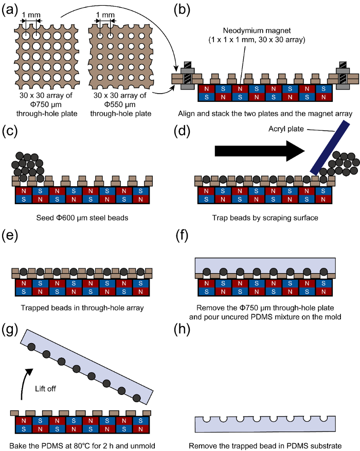
Figure 1: Schematic of fabrication process. (a) Making 30 x 30 Φ550 and 750 µm through-hole array in aluminum plates using CNC engraver. (b) Aligning the two through plates by using the alignment holes. Subsequently, the aligned plates were stacked on the magnet array. (c) Seeding a sufficient amount of steel beads onto the plates. (d) Scraping the beads using an acryl plate to trap the beads in the through-hole array. (e) Beads were trapped in the through-hole array. (f) The top plate (Φ750-µm through-hole array) was removed and uncured PDMS mixture was poured into the mold. (g) After the PDMS was baked at 80 ˚C for 2 h, the cured PDMS was unmolded. (h) The cured PDMS grabs the steel beads. The beads are then removed using a neodymium magnet (Φ15 mm with a thickness of 2 mm). Please click here to view a larger version of this figure.
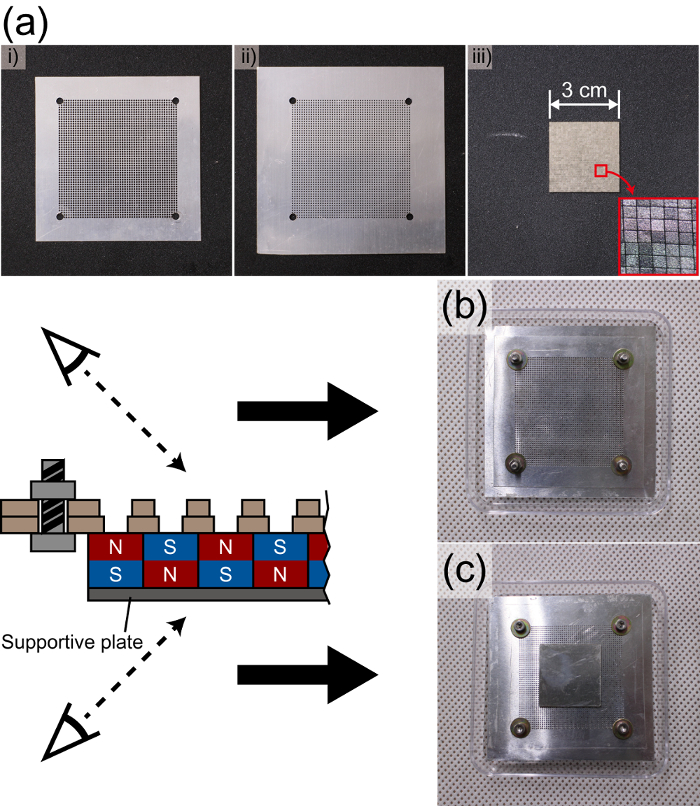
Figure 2: Fabrication process. (a) Preparing two through-hole plates and magnet array. i) Aluminum plate having 750 µm through-hole array. ii) Aluminum plate having 550 µm through-hole array. iii) 30 x 30 array of 1 mm x 1 mm x 1 mm magnets. (b) Top view of stacked and aligned plates. (c) Bottom view of stacked and aligned plates and magnet array. Please click here to view a larger version of this figure.
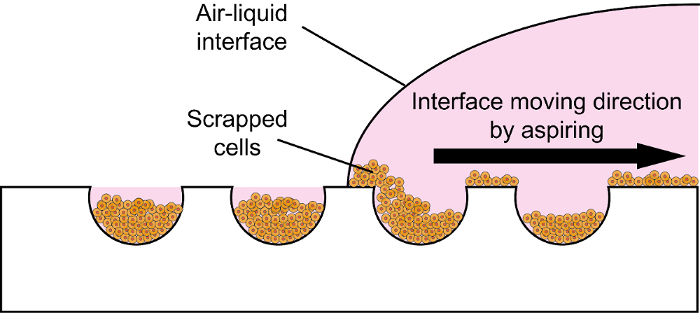
Figure 3: Removing excessive cells by receding meniscus. By aspiring the medium, the surface tension was caused by air-liquid interface, then the surface tension scrapped excessive cells on surface of microwell substrate. Please click here to view a larger version of this figure.
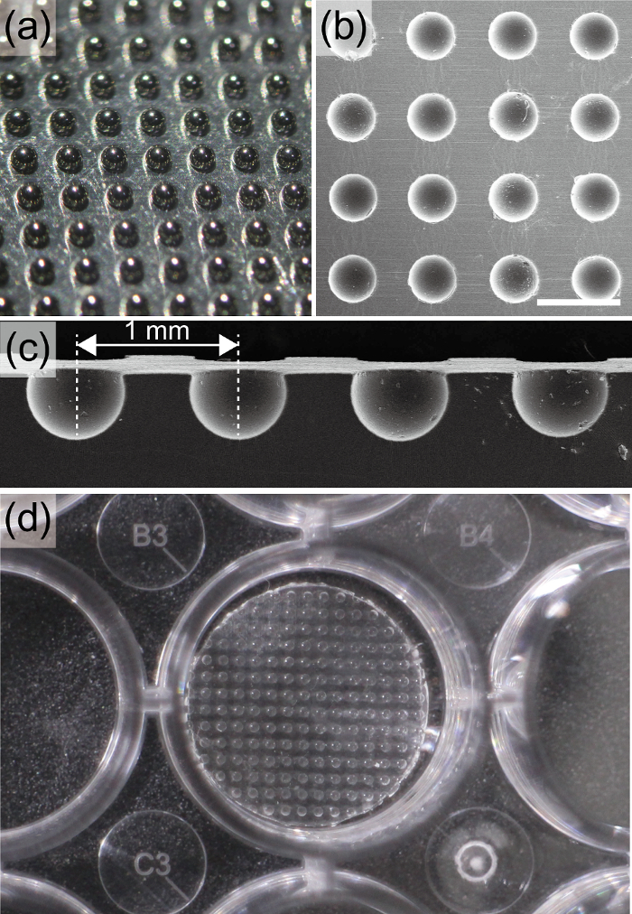
Figure 4: Convex mold and fabricated microwell array. (a) Trapped beads in through-hole array aluminum plate. The trapped beads act as a mold to fabricate the concave microwells. The bead size was 600 µm. The scale bar is 1 mm. (b) and (c) SEM images of fabricated microwells. Each fabricated microwell has a hemispherical shape, 600 µm in diameter. (d) Φ14-mm microwell array in 24-well plate. The array contains over 120 concave microwells. Please click here to view a larger version of this figure.
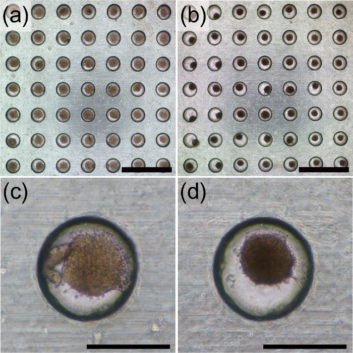
Figure 5: Culture spheroids in concave microwell array. The Φ14-mm microwell array was seeded with 2 x 10⁶ ASCs and cultured for 3 days. (a) Cultured spheroids at Day 1; the cells have started to form spheroids. The scale bar is 2 mm. (b) Cultured spheroids at Day 3; the formed spheroids are more tightly structured, while their average diameter has fallen from 185.68 ± 22.82 µm at Day 1 to 147.00 ± 17.11 µm at Day 3. The scale bar is 2 mm. (c) Magnification images of spheroid at Day 1. The scale bar is 500 µm. (d) Magnification images of spheroid at Day 3. The scale bar is 500 µm. Please click here to view a larger version of this figure.
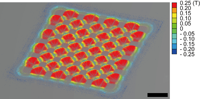
Figure 6: Simulation result for vector of magnetic flux density. The density of the magnetic flux on the magnet array was computed using the magnetostatic module. The simulation result shows that the strongest magnetic flux density is at center of each magnet, causing the beads to be trapped in the center of the through-holes where they became securely fixed. The scale bar is 2 mm. Please click here to view a larger version of this figure.
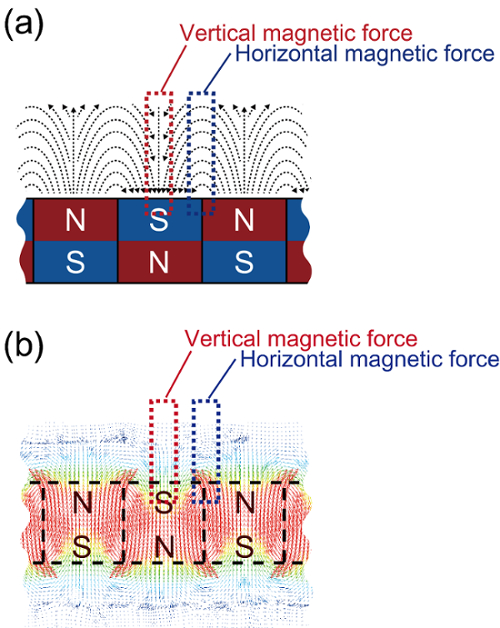
Figure 7: Magnetic field distribution of magnet array. Each magnet is of the opposite polarity to its neighbor. The horizontal magnetic field is dominant at the interface between neighboring magnets, while the vertical magnetic field is strongest at the center of each magnet. These directional forces guide a bead to the center of a magnet. (a) Magnetic field of magnet array. (b) Vector of magnetic field as determined by magnetostatic simulation. Please click here to view a larger version of this figure.
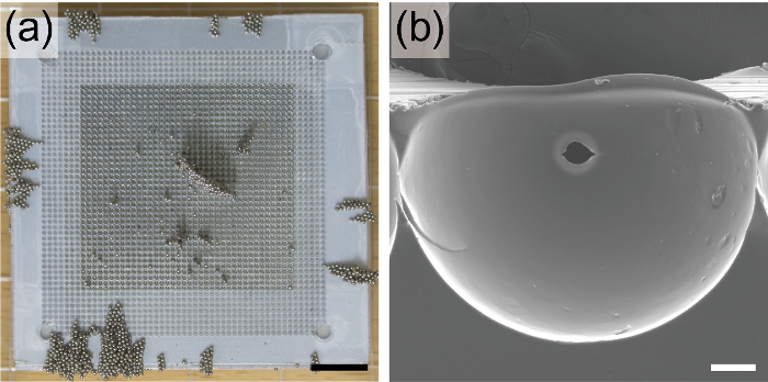
Figure 8: Limitation using single big magnet and of bead size. (a) Unlike the case of using an array of small magnets, when one large magnet is used, almost all of the beads tend to move to the edge or center of the magnet where the high density magnetic field is formed. Further, the beads are connected to form a chain shape. The scale bar is 10 mm. (b) SEM image of linked microwell which was fabricated by using Φ800 µm beads with 1 mm x 1 mm x 1 mm magnet array. Using a bead that is too large in size relative to the size of the magnet can create a small hole in the wall between adjacent microwells. The scale bar is 100 µm. Please click here to view a larger version of this figure.
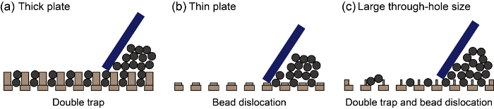
Figure 9: The importance of choosing the appropriate top plate thickness and hole size in the bead trapping process. (a) If the top plate is too thick, a double trap will occur. (b) Conversely, if the top plate is too thin, there is a tendency for the beads to come off. (c) If the size of the through-hole is larger than the bead diameter, both double trap and bead dislocation may occur. Please click here to view a larger version of this figure.
The major challenge facing this fabrication method was the secure fixing of the beads in the through-hole array in the aluminum plate. To solve this challenge, magnetic force in the form of a 30 x 30 magnet array was used to fix the beads securely, as shown in Figures 6 and 7. The magnetic flux density of the magnet array, which has the opposite polarity, is strongest at the center of each magnet surface. Because the strength of the magnetic force depends on the flux density, the beads were guided to the center of the top surface of each magnet where they were held in position. If a single large-sized magnet (5 cm × 5 cm × 1 cm) was used, the beads, especially the ones located in the extreme outside holes, tend to be attracted to the higher intensity magnetic field created at the magnet edge. Another problem with using large magnets is that the beads stick together spontaneously to create small bead chains (Figure 8a).
The role of top plate (750 µm hole) was to serve the pit geometry to trap beads. Due to this pit structure, it is possible to scratch the beads with an acrylic plate to create a large number of trapped bead arrays at once (protocol 2.4 and Figure 1c and 1d). If not using the top plate, each bead must be manually inserted into the base (550 µm hole) one at a time.
The limitations of our method include the need for a CNC engraver that is the most expensive device used in the method. Such CNC machines are priced from around $3000. This, however, is still much cheaper than conventional soft lithography facilities. Another inherent limitation of our method is the need for small magnets, and the gap between the microwells is dependent on the magnet size, which was 1 mm in the demonstration described in this paper. It would be difficult to reduce this gap much more since magnets smaller than 500 µm are not readily available. In addition, maximum size of bead was also limited. The trapped beads were magnetized by magnets. If the gap between magnetic beads were too narrow, the probability of sticking together is higher than some of the microwells were connected by holes as shown in Figure 8b. Therefore, when 1 mm x 1 mm x 1 mm magnets are used, beads with a diameter of 700 µm or more are not recommended
Compared with other fabrication methods such as flexible membrane14, ice lithography18 and deep reactive ion etching20, this fabrication method does not require special lithography facilities, allows the microwell position to be easily controlled, and can produce a standardized concave microwell shape. In addition, wet etching of PDMS21, grayscale lithography22, and backside diffused light lithography23 have been proposed for the production of concave geometries. However, wet etching of PDMS requires a rectangular structure first to make a concave and round microwell, and is not suitable for making an open microwell. The greyscale lithography method has the advantage of utilizing existing photo lithography facilities, but the need of high priced facilities and greyscale photo mask is a disadvantage. Backside diffused light lithography was another recently reported method useful to fabricate concave microwells with various aspect ratios, but only at the low resolution of pattern density.
The critical step in the concave microwell fabrication is the selection of the thickness of the and the through-hole size of top plate (step 1.1 and 1.3). If the through-hole plate is too thick, multiple beads can be trapped in each through-hole (Figure 9a); if it is too thin, the beads will not be fixed in step 2.4 and thus dislocated from the through-holes (Figure 9b). In case of the larger through-hole, both multiple trap and dislocation can occur (Figure 9c).
As a guideline for selecting the size of the magnet and the thickness of the through-hole plate, it is recommended that the size of the magnet and the thickness of the "through-hole plate" be based on the size of the bead. The size of the magnet must be larger than the diameter of the bead, and the thickness of the through-hole plate should not exceed the diameter of the bead. However, since the choice of magnets and plate thickness is empirical, more detailed optimization and parametric studies will be included in future studies.
Future goals of our method include the fabrication of stem cell niche-like microwells for biomimetic in vitro hair follicles24, customized microwells for organoid generation25, and diverse arrays of different-sized microwells for studying the dependence of cancer cells and immune cells on spheroid size.
The authors have nothing to disclose.
This research was supported by the Basic Science Research Program through the National Research Foundation of Korea (NRF) funded by the Ministry of Science, ICT and Future Planning (NRF-2014R1A1A2057527 and NRF-2016R1D1A1B03934418).
CNC rotary engraver | Roland DGA | EGX-350 | |
Micro drill bit | HAM Präzision | 30-1301 TA | Φ 0.55 and 0.75 mm |
Sulfuric acid 98% | Daejung | 7683-4100 | For cleaning aluminum plate. Dilute with distilled water with 15% solution |
Neodymium magnet | Supermagnete | W-01-N | 1 x 1 x 1 mm |
Bearing ball | Agami Modeling | SUJ2 | Φ 600 μm steel bead |
Polydimethylsiloxane (PDMS) | Dowcorning | Sylgard 184 | |
Pluronic F-127 | Sigma Aldrich | p2443 | Dilute with phosphate buffered saline to 4% (w/v) solution |
Dulbecco's modified eaggle's medium (DMEM) | ATCC | 30-2002 | |
Dulbecco's phosphate buffered saline (D-PBS) | ATCC | 30-2200 | |
Fetal bovine serum | ATCC | 30-2020 | |
Adipose-derived mesenchymal stem cells | ATCC | ATCC PCS-500-011 |