Here, we present protocols for analyzing bone remodeling within a lab-on-a-chip platform. A 3D printed mechanical loading device can be paired with the platform to induce osteocyte mechanostransduction by deforming the cellular matrix. The platform can also be used to quantify bone remodeling functional outcomes from osteoclasts and osteoblasts (resorption/formation).
Bone remodeling is a tightly regulated process that is required for skeletal growth and repair as well as adapting to changes in the mechanical environment. During this process, mechanosensitive osteocytes regulate the opposing responses between the catabolic osteoclasts and anabolic osteoblasts. To better understand the highly intricate signaling pathways that regulate this process, our lab has developed a foundationary lab-on-a-chip (LOC) platform for analyzing functional outcomes (formation and resorption) of bone remodeling within a small scale system. As bone remodeling is a lengthy process that occurs on the order of weeks to months, we developed long-term cell culturing protocols within the system. Osteoblasts and osteoclasts were grown on functional activity substrates within the LOC and maintained for up to seven weeks. Afterward, chips were disassembled to allow for the quantification of bone formation and resorption. Additionally, we have designed a 3D printed mechanical loading device that pairs with the LOC platform and can be used to induce osteocyte mechanotransduction by deforming the cellular matrix. We have optimized cell culturing protocols for osteocytes, osteoblasts, and osteoclasts within the LOC platform and have addressed concerns of sterility and cytotoxicity. Here, we present the protocols for fabricating and sterilizing the LOC, seeding cells on functional substrates, inducing mechanical load, and disassembling the LOC to quantify endpoint results. We believe that these techniques lay the groundwork for developing a true organ-on-a-chip for bone remodeling.
Bone is a highly dynamic tissue that requires intricate coordination among the three major cell types: osteocytes, osteoblasts, and osteoclasts. Multicellular interactions among these cells are responsible for the bone loss that occurs during paralysis and long-term immobility and for the bone formation that occurs in response to growth and exercise. Osteocytes, the most abundant bone cell type, are highly sensitive to mechanical stimuli applied to the bone. Mechanical stimulation alters osteocyte metabolic activity and leads to an increase in key signaling molecules1,2. Through this process, known as mechanotransduction, osteocytes can directly coordinate the activities of osteoblasts (bone forming cells) and osteoclasts (bone resorbing cells). Maintaining bone homeostasis requires a tight regulation between bone formation and bone resorption rates; however, disruptions in this process can result in disease states such as osteoporosis or osteopetrosis.
The complexity of interactions between these three cell types lends itself well to investigation utilizing microfluidic and lab-on-a-chip (LOC) technologies. To that end, our lab has recently established proof of concept of a LOC platform for analyzing bone resorption and formation (functional outcomes) in the bone remodeling process. The platform can be used for the study of cellular interactions, altered loading environments, and investigational drug screening. In recent years, various microfluidic devices have been developed for investigating the molecular signaling pathways that regulate bone remodeling; however, many of these systems quantify remodeling through indirect markers that are indicative of functional activity3,4,5,6,7. An advantage of our system is that it can be used for direct quantification of functional outcomes. Bone remodeling is a long-term process. As such, direct quantification of bone resorption and formation requires a culturing system that can be maintained for a minimum of several weeks to months8,9,10,11. Thus, when developing the LOC platform, we established long-term culturing protocols necessary for formation and resorption and have maintained cells within the system for up to seven weeks11. Additionally, we incorporated appropriate culturing substrates for both cell types into the platform; osteoclasts were cultured directly on bone, and osteoblasts, which are known to be plastic adherent, were cultured on polystyrene discs. Further, we addressed issues concerning sterility, long-term cytotoxicity and chip disassembly for remodeling analysis11,12.
The LOC platform can also be used to induce osteocyte mechanotransduction through matrix deformation. A 3D printed mechanical loading device was developed to pair with the LOC and apply a static out of plane distention to stretch the cells13. To accommodate this mechanical load, the depth of the well within the LOC was increased. This small scale, simple mechanical loading device can be easily produced by labs with limited engineering experience, and we have previously shared drawings of the 3D printed components13. In the current work, we demonstrate some of the novel techniques necessary for the successful use of the LOC. Specifically, we demonstrate chip fabrication, cell seeding on functional substrates, mechanical loading and chip disassembly for remodeling quantification. We believe that the explanation of these techniques benefit from a visual format.
1. Chip mask preparation
NOTE: Steps 1.1 – 1.3 only need to be performed once upon initial receipt of the chip mask. They ensure the mask does not bow during use. The design of the microfluidic masks was previously described11,14. Masks were designed in-house and commercially fabricated using high resolution stereolithography (Figure 1A).
2. PDMS fabrication
NOTE: A shallow-well (1 mm) chip design is used for functional activity (formation and resorption) assays, and a deep-well (10 mm) chip design is used for mechanical loading studies. The bottom of the deep-well is formed by attaching a separate thin PDMS membrane (Figure 1B).
3. Functional activity substrates
NOTE: Polystyrene discs and bone wafers must be attached to the bottom of wells that will be used for osteoblast and osteoclast cultures, respectively.
4. Chip assembly and sterilization
5. Mechanical loading device assembly
NOTE: The design and fabrication processes for the 3D printed mechanical loading device (Figure 2A-C) were previously described and all design files for printed components have been previously provided13.
6. Experimentation
NOTE: Protocols for functional activity experiments were previously provided11,12.
The shallow-well configuration can be used for analyzing functional activity of osteoblasts and osteoclasts. Bone formation via osteoblasts and resorption via osteoclasts requires culturing times on the order of several weeks to months. Bone formation from MC3T3-E1 pre-osteoblasts was quantified using alizarin red and von Kossa stains11,15. At day 49, the average surface area stained with alizarin red was 10.7% ± 2.2% (mean ± standard errors of the mean)11. The average surface area stained with von Kossa was 6.4% ± 1.6%11. Figure 4A shows typical formation results from osteoblast cultures at day 49 stained with alizarin red and von Kossa. Bone resorption from RAW264.7 pre-osteoclasts was quantified using toluidine blue staining 11,15. At day 30 the average surface area stained with toluidine blue was 30.4% ± 4.5%11. Figure 4B shows typical bone resorption results from osteoclast cultures stained with toluidine blue at day 30. Scanning electron microscopy was performed to verify the presence of resorption pits. Typical results are shown in Figure 4C. These results demonstrate that cells within the device remain viable and functionally active for at least seven weeks.
A 3D printed loading device was designed and fabricated to accommodate the deep-well chip configuration. Together, this system can induce osteocyte mechanotransduction by stretching the cells via a static out-of-plane distention. The 48 h incubation of the chip described in step 4.9 has proven to be a critical process for maintaining cell viability and typical morphology. Figure 5A shows representative images of MLO-Y4 osteocytes at 72 h seeded in chips with and without this incubation period. During bouts of loading, osteocytes were exposed to a strain gradient induced on the PDMS membrane on which the cells were seeded (Supplementary Video 1). The equivalent strains generated during this process were modeled with FEA13 and the average equivalent strain produced on the top of the PDMS membrane was determined. Figure 5B shows the relationship between average equivalent strain and platen displacement for values between 1 and 2 mm. A representative heat map of the induced strain gradient is shown in Figure 5C. In this example, a platen displacement of 1.5 mm generated an average equivalent strain of 12.29% on the top of the membrane. This model also demonstrates that the strains induced near the center of the well are relatively low and gradually increase radially outward, with maximum strains generated directly above the outer edge of the platen. Following loading, cell viability was analyzed with lactate dehydrogenase staining and the annexin V and dead cell assay14,16. Typical results are shown in Figure 5D,E, respectively.
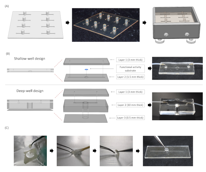
Figure 1: Microfluidic device. (A) Fabricating and leveling the chip mask. (Left) Schematic of the deep-well chip mask that was designed in-house using CAD software. (Middle) Image of the deep-well chip mask that was commercially printed using high-resolution stereolithography. (Right) The mask is placed within a 3D printed leveling box to ensure the mask remains level during the casting of layer 2 of the chips. (B) Schematic sketches of the shallow-well and deep-well designs of the device. (Top) The shallow-well design was used for analyzing functional activity (formation and resorption) of osteoblasts and osteoclasts. This configuration is formed from two PDMS layers. A functional activity substrate was secured to the bottom of the culture well prior to sealing the layers together. Polystyrene discs and bone wafers were used for osteoblast and osteoclast cultures, respectively. (Bottom) The deep-well design was used for applying mechanical load to osteocytes. This configuration consists of three PDMS layers. The bottom of the culture well is formed by the deformable PDMS membrane (layer 3). (C) Fabrication steps for the polystyrene disc used for osteoblast cultures. The back of a tissue culture treated coverslip was marked with masking tape. Individual discs were cut out with a cork-borer. The disc was cleaned with ethanol and a cotton swab. The tape backing was removed and disc was attached to the bottom of the PDMS culture well. Please click here to view a larger version of this figure.
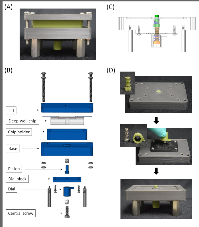
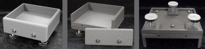
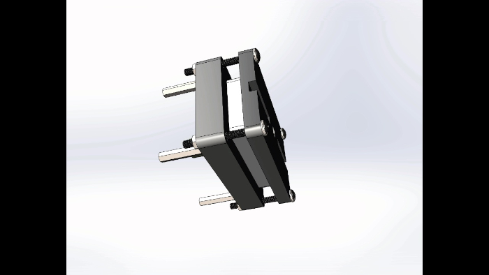
Figure 2: Design and assembly of the mechanical loading device. (A) Image of the assembled mechanical loading device. When coupled with the deep-well design of the PDMS chip, the loading device stretches cells by applying an out of plane distention to a deformable membrane. (B) Exploded-view of the device. All parts shown in blue were 3D printed with a heat resistant polylactic acid filament. All hardware is stainless steel. (C) Screw jack mechanism of the loading device. Rotation of the central screw (orange) pushes the platen (green) upward through the base. The upward movement of the platen deforms the PDMS membrane of the deep-well chip on which the cells have been seeded. (D) Assembly process of the loading device. Please click here to view a larger version of this figure.
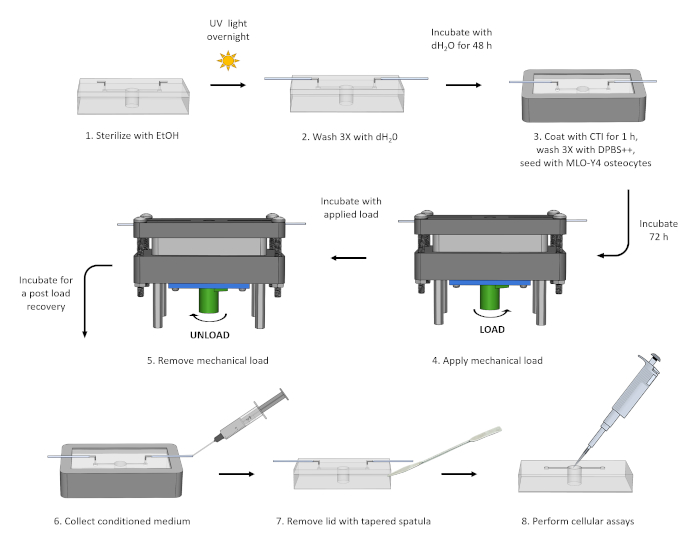
Figure 3: Mechanical loading experiment. All liquids were administered and removed from the chip using a 5 mL syringe connected to the access tubing. A critical step in this process is the 48 h incubation with sterile distilled water prior to cell seeding. Without this incubation cells showed low viability and atypical morphology. Please click here to view a larger version of this figure.
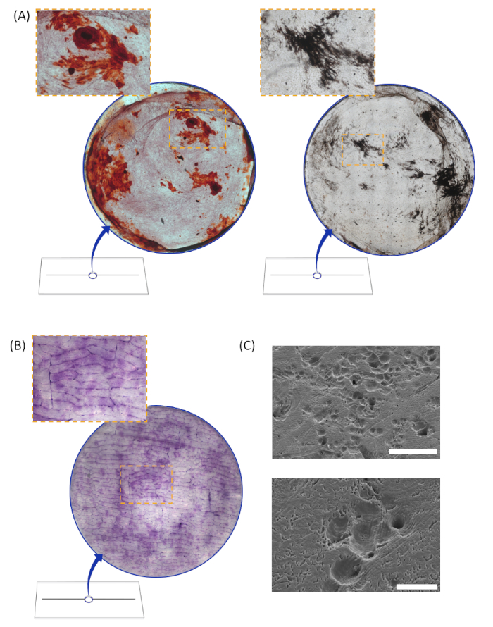
Figure 4: Typical functional activity results. (A) Typical formation results stained with alizarin red (left) and von Kossa (right) from induced MC3T3-E1 osteoblast cultures at day 49. Whole disc images measure 5.4 mm in diameter. (B) Typical osteoclast resorption results from RAW264.7 preosteoclasts induced with receptor activator of nuclear factor kappa-B ligand (RANKL). Cells were cultured on bone wafers and stained with toluidine blue at day 30. (C) Typical scanning electron microscopy images verifying the presence of resorption pits on bone wafers. The scale bar in the top image represents 200 µm and scale bar in the bottom image represents 50 µm. Please click here to view a larger version of this figure.
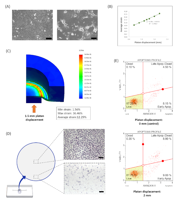
Figure 5: Effects of mechanically induced strain on osteocytes. (A) Images of MLO-Y4 osteocytes at 72 h in the deep-well chip fabricated with (left) and without (right) a 48 h incubation with distilled water prior to cell seeding. (B) Finite element analysis was used to model the average equivalent strain generated on the top of the deformable PDMS membrane based on the displacement of the loading device platen. Results from displacements between 1.0 mm and 2.0 mm are shown. (C) Heat map of the modeled strain gradient induced on the PDMS membrane for a platen displacement of 1.5 mm. (D) Typical results of a lactate dehydrogenase stain of drug induced osteocytes that were stretched using a 1.5 mm platen displacement. A lighter cell staining is observed near the outer edge of the well, which corresponds to the location of higher strain values indicative of cell damage and/or death. (E) Representative flow cytometry results of load-induced apoptosis indicated by an annexin V and dead cell assay. Please click here to view a larger version of this figure.
Supplementary Figure 1: 3D printed leveling box with detachable wall. Please click here to view a larger version of this figure.
Supplementary File 1: Leveling box CAD file 1. Please click here to view this file (Right click to download).
Supplementary File 2: Leveling box CAD file 2. Please click here to view this file (Right click to download).
Supplementary File 3: Leveling box CAD file 3. Please click here to view this file (Right click to download).
Supplementary File 4: Leveling box hardware list. Please click here to view this file (Right click to download).
Supplementary Video 1: Mechanical loading device. Please click here to view this file (Right click to download).
This article describes the foundations for fabricating a bone remodeling LOC platform for culturing osteocytes, osteoclasts, and osteoblasts. By altering the depth and size of the well within the chip, multiple configurations were developed for stimulating osteocytes with mechanical load and quantifying functional outcomes of bone remodeling (Figure 1B).
During chip assembly, optimizing the plasma oxidation protocol was critical for eliminating leakage concerns. We found that exposing PDMS surfaces to 30 s of oxygen plasma generated using a medium RF power setting (step 4.1), equal to approximately 10.2 W, was sufficient for creating a strong bond between the layers. The integrity of the bond decreased when longer exposure times or a higher RF power setting were used. This is consistent with previous reports that noted an overexposure of PDMS to oxygen plasma increased surface roughness and reduced adhesiveness17,18.
Additionally, maintaining high cell viability and typical cell morphology was critically dependent on the PDMS curing process. The PDMS polymer consists of crosslinked dimethylsiloxane oligomers. This crosslinking process is both time and temperature dependent; however, even with extensive curing the polymer fails to fully polymerize19. The remaining oligomers have been shown to leach out of the bulk polymer into surrounding cell culture medium and have even been found in the membranes of cells grown on the polymer surface20. Several groups have reported cytotoxic effects from non-crosslinked PDMS oligomers21,22,23. To address this concern in our system, we optimized the PDMS curing process. Although the curing rate for PDMS is temperature dependent, the material properties of our chip masks restricted our curing temperature to 45 °C. As such, we determined that the chips should be baked for a minimum of 18 h. Further, we have found that incubating chips with dH2O for at least 48 h prior to cell seeding (step 4.9) was necessary to reduce cytotoxic effects. Figure 5A shows MLO-Y4 osteocytes cultured in chips with and without this incubation period.
The deep-well configuration, which was designed to accommodate mechanical load application, requires that the chip be fabricated from three separate layers. Unlike the shallow-well configuration, fabricating the well and membrane portions as a single piece for the deep-well configuration caused the membrane to warp. This may be due to a difference in curing rates between the thick and thin portions of the chip. To overcome this issue, the membrane layer was constructed separately and bonded to the bottom of the chip following the curing process. To generate a separate membrane layer with uniform thickness, it is critical that the leveling box be completely level prior to adding the PDMS (step 1.4). As such, the use of a digital protractor is recommended to ensure a high degree of accuracy. Additionally, during step 2.3.2, it is critical to remove as much PDMS from the plastic cup as possible. Inconsistencies at this step will lead to high deviations in membrane thicknesses, and ultimately high deviations in the average substrate strain used to induce osteocyte mechanotransduction.
Our bone remodeling platform provides a high degree of versatility. This system can be used to investigate a variety of factors that regulate bone remodeling, such as load-induced mechanotransduction, multicellular signaling, inflammation, or drug effects. For example, the system was used to analyze the combined effects of mechanical load and inflammation on bone remodeling in a drug induced environment14. Mechanical load was applied to bisphosphonate-treated osteocytes. Protein analysis of the conditioned medium revealed a significant increase in the levels of leptin and osteonectin and a significant decrease in the levels of CCL21 and CD36 when compared to osteocytes that were not mechanically loaded14.
The protocols presented here provide a foundation for culturing each cell type within the LOC as well as methods for inducing mechanical load and quantifying functional activity. Moving forward, we are working towards a true bone organ-on-a-chip. Additionally, we believe that using our system to develop mathematical modeling systems could greatly enhance our understanding of the complex multicellular signaling processes that regulate bone remodeling24,25.
The authors have nothing to disclose.
This work was supported by the National Science Foundation under Grant Nos. (CBET 1060990 and EBMS 1700299). Also, this material is based upon work supported by the National Science Foundation Graduate Research Fellowship Program under Grant No. (2018250692). Any opinions, findings, conclusions, or recommendations expressed in this material are those of the authors and do not necessarily reflect the views of the National Science Foundation.
Acrylic sheet | Optix | — | 3.175 mm thick |
Angled dispensing tips | Jensen Global | JG18-0.5X-90 | Remove plastic connector prior to use |
Biopsy punch | Robbins Instruments | RBP-10 | 1 mm diameter |
Bone wafers | Boneslices.com | 0.4 mm thick | Bovine cortical bone |
Bovine calf serum | Hyclone | SH30072 | |
Calipers | Global Industrial | T9F534164 | |
Cell spatula | TPP | 99010 | |
Chip mask | ProtoLabs | Custom-designed | Print material: Accura SL 5530 |
Cork borer | Fisher Scientific | 07-865-10B | |
Cotton tipped applicator | Puritan | 806-WCL | |
Culture dish (100 mm) | Corning | 430591 | Sterile, Non-tissue culture treated |
Culture dish (150 mm) | Corning | 430597 | Sterile, Non-tissue culture treated |
Double sided tape | 3M Company | Scotch 237 | |
Fetal bovine serum | Hyclone | SH30910 | |
Forceps | Fisher Scientific | 22-327379 | |
Leveling box | Custom-made | — | 3D printed |
Masking tape | 3M Company | Scoth 2600 | |
MC3T3-E1 preosteoblasts | ATCC | CRL-2593 | Subclone 4 |
Mechanical loading device | Custom-made | — | 3D printed |
Minimum essential alpha medium | Gibco | 12571-063 | |
MLO-Y4 osteocytes | — | — | Gift from Dr. Lynda Bonewald |
Packaging tape | Duck Brand | — | Standard packaging tape |
Paraffin film | Bemis Parafilm | PM999 | |
Penicillin/streptomycin | Invitrogen | p4333 | |
Plasma cleaner | Harrick Plasma | PDC-001 | Expanded plasma cleaner |
Polydimethylsiloxane kit | Dow Corning | Sylgard 184 | |
Polystyrene coverslips | Nunc Thermanox | 174942 | Sterile, tissue culture treated |
Oven | Quincy Lab | 12-180 | |
RAW264.7 preosteoclasts | ATCC | TIB-71 | |
Scalpel | BD Medical | 372611 | |
Silicone tubing | Saint-Gobain Tygon | ABW00001 | ID: 1/32" (0.79 mm), OD: 3/32" (2.38 mm) |
SolidWorks software | Dassault Systèmes | — | Used to generate 3D printed models and perform FEA |
Spray adhesive | Loctite | 2323879 | Multi-purpose adhesive |
Syringe (5 ml) | BD Medical | 309646 | Sterile |
Syringe pump | Harvard Apparatus | 70-2213 | Pump 11 Pico Plus |
Tapered laboratory spatula | Fisher Scientific | 21-401-10 | |
Two-part expoxy | Loctite | 1395391 | 5 minute quick set |
Type I collagen | Corning | 354236 | Rat tail collagen |
Vacuum desiccator | Bel-Art | F42010-0000 | |
Waterproof sealant | Gorilla | 8090001 | 100% silicone sealant |