1. Calculate Mass of PDMS and Additives
- Use the following equation to find the mass of PDMS needed for specific heights in the following procedures,
M = ϱ*V = ϱ * Height*Area (1),
where 'Height' is the height of the layer, 'Area' is the area of a container that the PDMS will be cured in, 'ϱ' is the density of the mixture and 'V' is the volume.
NOTE: Densities for height calculations are PDMS = 0.965 g/mL, Ni-PDMS = 1.639 g/mL, MB-PDMS = 0.648 g/mL. - Use equation (1) to estimate the mass of PDMS needed, for a given container, to obtain a specific height (5 mm) for the base of the biological actuator. The resulting density of PDMS is 0.965 g/mL.
NOTE: The ratio is 10:1 base to curing agent by weight.
Mbase = ϱ*V = ϱ*V*( ) (2)
) (2)
Mcuring agent = ϱ*V = ϱ*V*( )
) - Use equation (1) to find the mass of Ni-PDMS needed, for a given container, to obtain a specific height (1.5 mm) of the bottom base of the biorobot.
NOTE: The ratios are 1:1.88 (Nickel Powder to PDMS by weight) and 1:1.71:0.171 (Nickel Powder to PDMS Base to PDMS curing agent by weight). The resulting density of Ni-PDMS will be 1.639 g/mL.
MNickel = ϱ*V = ϱ*V*( ) (3)
) (3)
Mbase = ϱ*V = ϱ*V*( )
)
Mcuring agent = ϱ*V = ϱ*V*( )
) - Similarly, use equation (1) to find the mass of MB-PDMS needed, for a given container, to obtain a specific height (3.5 mm) of the top base of the biorobot.
NOTE: The ratios are 1:5 (microballoons to PDMS by weight) and 1:4.54:0.454 (microballoons to PDMS base to PDMS curing agent by weight). The resulting density of MB-PDMS will be 0.648 g/mL.
MMicroballoon = ϱ*V = ϱ*V*( ) (4)
) (4)
Mbase = ϱ*V = ϱ*V*( )
)
Mcuring agent = ϱ*V = ϱ*V*( )
) - Check the dynamic stability of the biorobot with the desired dimension and geometry using the analysis scripts; see the supplementary information, 'Biorobot_dynamic_stability.m' and 'CG_CB_calculation.m'.
2. Fabrication of Biological Actuators on a Stationary Base
NOTE: See Figure 1a.
- Spin-coat a thin film of PDMS (see Figure 1a-1 and a2). The thickness of the resulting PDMS film will be 25 µm.
- Place a silicon wafer on a photoresist spinner and flip the pump switch on to produce suction.
NOTE: The silicon wafer has a 4-inch diameter and 500 µm thickness. - Pour positive photoresist (e.g. S1808) onto the silicon wafer until the wafer is completely covered. Program the spinner to spin at 2,000 rpm for 20 s. Then, engage the spinner by pressing on the foot pedal. Turn off the suction after spinning.
- Heat a hot plate up to 120 °C. Use wafer tweezers to pick up the silicon wafer from the spinner and place the silicon wafer directly on the hotplate. Cover the wafer with a shallow petri dish and bake for 10 min.
NOTE: An oven can be used to bake the wafer using the same temperature and duration. Figure 1a-1 depicts this process. - Place a plastic container on a weighing scale and zero it out. Pour 6 g of PDMS base into the container and add 0.6 g of PDMS curing agent. Mix the PDMS thoroughly for 5 min.
NOTE: After mixing, the mixture should be confluent with bubbles. - Place the container of mixed PDMS into a vacuum chamber. Reduce the pressure of the vacuum chamber to 100 mbar and leave the container in the chamber for 30 min. Break the vacuum, and remove the container. Keep the container covered until use.
- Place the silicon wafer with the baked photoresist layer on the spinner. Slowly pour the entire degassed PDMS mixture on the wafer.
NOTE: Pour slowly so that no new bubbles are introduced into the mixture. - Set the spinner to 1,200 rpm for 5 min. Turn on the spinner suction and engage the spinner. Turn off the suction after spinning.
NOTE: These settings result in a 25 µm thick layer of PDMS. - Heat an oven to 40 °C. Use wafer tweezers to pick up the silicon wafer from the spinner, then place it in the oven. Bake the wafer overnight and then cool the wafer at room temperature.
NOTE: Figure 1a-2 depicts this process.
- Place a silicon wafer on a photoresist spinner and flip the pump switch on to produce suction.
- Laser engraving of the thin-film PDMS layer.
- Turn on the power switch of the laser engraver and its exhaust. Turn on the computer connected to the laser engraver. Open the laser engraver software.
- Under the "File" option, open the biological actuator design file shown in Figure 2e.
- Press the "Settings" button. Click on "Blue" and change the power setting to 3% and speed to 4%. Click “Set”. Click on "Black" and change the "Mode" to skip. Then click “Set”. Do the same for "Red". Press the "Apply" button to finish the settings.”
- Push the "Activate the Engraver" button at the top right.
- Press the "Relocate" button to move the design into the center of the software's screen.
- Press the "Focus View" button in the program and click on the edge of the biorobot on the screen. This will move the guiding laser dot of the laser engraver to the corresponding point.
- Move the wafer manually with tweezers, so that the point on the wafer corresponding to the point clicked in 2.2.4 is directly under the guiding laser dot.
- Press the "Start engraving the prior job" button to start the engraving process. Remove the wafer after the engraving is completed. Turn off all equipment.
NOTE: The "Start engraving the prior job" button is the large green triangle. Do not look directly at the engraving process as the laser can damage the eyes. Figure 1a-3 depicts this process.
- Preparation and fabrication of the biological actuator base.
- Pour glass beads (3 mm diameter) into a 15 mL tube. Immerse the beads with 70% ethanol in DI water for 24 h. Remove the ethanol and fill the tube with DI water for 24 h. Pour out the DI water and place the tube on a hotplate at 50 °C to facilitate drying of the glass beads.
- Add 3 g to the amount of PDMS found in equation (1) to account for the PDMS that will stick to container sides during pouring. Use equation (2) to find PDMS base and curing agent amounts.
- Place a plastic container on a weighing scale and zero it out. Pour the amount of PDMS base found in step 2.3.2 into the container and zero it out. Then pour the amount of PDMS curing agent found in step 2.3.2 into the container.
- Mix the PDMS thoroughly for 5 min.
NOTE: PDMS is used at a ratio of 10:1 base to curing agent. The mixture should have many bubbles. - Place a container to be used for baking on a scale and zero out. Carefully pour out the correct amount of PDMS found in step 2.3.2 (and mixed in step 2.3.4) into the container. Drop cleaned glass beads throughout the PDMS mixture at regular intervals. Leave a minimum of 5 mm of space surrounding each bead for the biological actuator base.
- Place the container into a vacuum chamber. Reduce the vacuum pressure to 100 mbar and turn off the vacuum pump. After 30 min, break the vacuum and remove the container. Keep covered until use.
NOTE: The pressure in the chamber may rise slowly over time as the mixture degasses and the vacuum chamber leaks. If the pressure increases substantially over 100 mbar, turn on the vacuum pump to restore the pressure to 100 mbar. - Heat a hotplate to 40 °C. Carefully place the container of PDMS and the glass beads on the hot plate. Cover the container and bake overnight.
- Biological actuator assembly.
NOTE: The following procedure can be done with the naked eye.- Cut cubes (5 mm x 5 mm x 5 mm) out of the bulk PDMS made in part 2.3 using a razor blade.
NOTE: One bead should be in the center of each cube. - Clean all sides of each biological actuator base, to remove any contaminates on the base surfaces, by pressing the base into the tape and remove. Repeat for each side.
- Redo steps 2.3.2 to 2.3.6 to make a small amount of liquid PDMS. Dip the tip of a needle into the liquid PDMS. Place a drop of the liquid PDMS on the engraved base area of the wafer patterned in step 2.2. Smear the droplet of PDMS so that it completely covers the 5 mm x 5 mm base area.
NOTE: The base area is the middle square section in Figure 2a. - Use tweezers to place the cleaned cube from step 2.4.2 on the base area that is covered with liquid PDMS.
- Repeat step 2.4.3 from "Place a drop of liquid PDMS" to the end and step 2.4.4 for each device that will be made.
- Heat a hotplate to 40 °C. Carefully place the silicon wafer with the assemblies on the hot plate. Cover the wafer and bake overnight.
NOTE: Keep the assemblies attached until use. Figure 1a-4 depicts the final device.
- Cut cubes (5 mm x 5 mm x 5 mm) out of the bulk PDMS made in part 2.3 using a razor blade.
3. Fabrication of Biorobots (Figure 1b)
- Spin-coating and laser-engraving a thin PDMS film
- Repeat all steps in 2.1 and 2.2 using a new silicon wafer. This will result in a silicon wafer with a thin film of PDMS and a thin film of the photoresist, which is engraved with a biorobot design.
NOTE: While repeating step 2.2, use the biorobot design for laser engraving instead of the biological actuator design previously used. Figures 1b-1 and b-3 depicts these processes.
- Repeat all steps in 2.1 and 2.2 using a new silicon wafer. This will result in a silicon wafer with a thin film of PDMS and a thin film of the photoresist, which is engraved with a biorobot design.
- Preparation and fabrication of PDMS composites.
NOTE: The following procedure can be done with the naked eye.- Pour phenolic microballoons into a 50 mL tube until full. Fill the tube with 70% ethanol in DI-water and let it sit for 24 h. Pour out the ethanol, add DI water, and let it sit for 24 h. Pour out the DI water, and then place the tube on a hotplate at 50 °C to facilitate the drying of the microballoons before use.
- Use equation (1) with the MB-PDMS density and 3.5 mm height to find the volume of PDMS required. Add 3 g to the total amount, to account for the material that will remain in the container after pouring. Use equation (3) to find the PDMS base and curing agent amounts. Measure out the appropriate amount of PDMS base, curing agent, and microballoons using the scale.
- Use equation (1) with Ni-PDMS density and 1.5-mm height to find the volume of PDMS needed. Add 3 g to the total amount as in step 3.2.2. Use equation (2) to find the PDMS base and curing agent amounts. Measure out the appropriate amount of PDMS base, curing agent, and nickel powder using the scale.
- Mix each mixture of MB-PDMS and Ni-PDMS for 5 min. Carefully pour the correct amount of MB-PDMS and Ni-PDMS calculated in 3.2.2 and 3.2.3 into separate containers using a scale.
NOTE: The mixtures should be thoroughly mixed by a metal or glass rod without scratching the bottom surface of the mixing container. The mixture will be confluent with bubbles. - Place both containers into a vacuum chamber. Reduce its pressure to 100 mbar for 30 min. Break the vacuum and remove the containers. Keep covered until use.
- Heat a hotplate to 40 °C. Place containers with MB-PDMS and Ni-PDMS on the hot plate. Cover each container and bake overnight.
NOTE: Store with a lid until use.
- Biorobot assembly.
- Cut biorobot bases of dimensions respective to each biorobot size from Ni-PDMS and MB-PDMS using a razor blade. See Figure 2b-2d for base designs.
NOTE: The thicknesses of Ni-PDMS is 1.5 mm and that of MB-PDMS is 3.5 mm. - Clean all sides of the biorobot bases to remove any contaminants on the surfaces, by pressing the base into the tape and removing. Repeat for each side.
- Turn on a corona discharger. Bring the tip of the corona discharger 1 cm above the Ni-PDMS base, which is placed on a metal plate with a cleanroom tissue in between. Move the tip around the base and continue for 15 s to treat the surface.
NOTE: A discharge should occur between the corona discharger and the wafer. If it does not, bring the tip closer until a discharge occurs. - Repeat step 3.3.3 to treat the surface of the base of a biorobot engraved in step 3.1 for the same duration. Use tweezers to place the Ni-PDMS treated side onto the treated side of the film. Let the device sit for 5 min.
NOTE: This will strongly bond the two parts. See Figure 1b4. - Use sharp tweezers to peel the biorobot cantilever from the wafer and place it on the bottom of the Ni-PDMS base. Use tweezers to remove the entire assembly from the wafer.
NOTE: The cantilever will be attached to the Ni-PDMS base. Figure 1b-5 and b-6 depicts this. - Place a small drop of uncured PDMS (10:1 base to curing agent) on the top of the MB-PDMS base. Use tweezers to place the side of the Ni-PDMS with the thin film PDMS on the MB-PDMS with the uncured PDMS. Place the assembly in a plastic petri dish, and then place this on a hotplate at 40 °C to cure overnight.
NOTE: Figure 1b-7 depicts the final device.
- Cut biorobot bases of dimensions respective to each biorobot size from Ni-PDMS and MB-PDMS using a razor blade. See Figure 2b-2d for base designs.
4. Functionalization of the Devices
NOTE: Below, we describe the process of preparing the devices for cell seeding.
- Prepare the required materials: Fibronectin solution (50 µg/mL), Phosphate Buffer Saline solution (PBS), Dulbecco's Modified Eagle Medium (DMEM) supplemented with 10% Fetal Bovine Serum (FBS) and 1% Penicillin antibiotic (DMEM complete).
- Place 100 µL of fibronectin solution into the center of a T-25 culture flask (bottom surface when the flask is sitting upright). Maintain separate flasks for each device.
- Place the biorobot or the biological actuator facing down over the droplet of fibronectin solution. Ensure that the cantilever is unfolded and immersed within the droplet. Incubate at 37 ℃ for 30 min.
- After the incubation, remove the fibronectin solution and wash with PBS twice.
- Remove the PBS and fill the flask with 10 mL of DMEM. Incubate at 37 ℃ for 1 h to facilitate degassing of the PDMS. To submerge the biorobots in 10 mL of media, use a magnet to hold the device at the bottom of the flask. Place the flask with the samples in an ultrasonication bath for 5 min to remove the bubbles.
NOTE: During the incubation period, air bubbles form on the PDMS surface, which is referred to as degassing here. The Ni-PDMS used in the biorobot assembly is magnetic. The biological actuator does not need a magnet because it will remain at the bottom of the flask due to the weight of the glass bead. The biorobot or the biological actuator assembly is now ready for seeding, which is explained in detail in part 2.
The biological actuator and biorobot have very similar fabrication processes, as the biorobot is a natural extension of the biological actuator (Figure 1). The biological actuator was developed first to establish techniques required for the biorobot, to analyze the force generated by the cells, and to characterize the cell maturation mechanically and biochemically, both of which are described in detail in Part 2 of this two-part article as well as in our recently published work15.
The spring constant of the actuator was assessed and tuned for a large change in radius of curvature of the cantilever during full contraction of the cardiomyocyte sheet. Then, we designed the biorobot while giving special consideration to its stability, control during cell seeding, and ease of locomotion. Initially, a few designs were chosen, as shown in Figure 2b-2d, with different properties to assess which attributes contribute the most to the design requirements. Biorobots were designed and tested with short, long, and wide cantilevers, as well as with multiple cantilevers to test the effect of changes in the actuator on biorobot function. We also considered different sizes of the floating base. The geometry of the base was maintained as a triangle as it creates the asymmetry that would result in a directional movement.
The stability of the biorobot was a critical component in the design process. The top MB-PDMS layer was used to provide buoyancy to the device, while the bottom Ni-PDMS layer was used for stability and magnetic control. Owing to a higher density, the base layer made of nickel provides the biorobot the ability to keep itself upright and return to its original position after exposure to external disturbances; shown in Figure 3. The layer also provides sufficient weight to keep the device afloat at the appropriate level. In this study, we provide an alternate approach, to develop a biorobot, which focuses on varying the properties of the mechanical backbone to create a self-stabilizing structure. Unlike other biorobots in the literature, the biorobot developed here can maintain its own pitch, roll and immersion depth. These parameters can be tuned by varying the mixing ratios of each composite material and their volume. However, there is a limit to total thickness of each base within the device beyond which the stability is compromised.
The following equation can describe the height of the biorobots above the surface of the medium:
where HNi, HMb, ρmedium, ρMb, and ρNi are thickness of Ni-PDMS, thickness of MB-PDMS, density of the medium, density of MB-PDMS, and density of Ni-PDMS, respectively (See Figure 3b). The height of the biorobots is one critical factor that affects the maximum load it can carry and its stability. Additional weight loaded on the base will lower the biorobots into the media and a larger volume of the base will be submerged. The additional volume to be submerged has a density lower than that of the medium and produces extra buoyancy to lift the added weight. Hence, to increase the maximum carrying load we need to increase h as much as possible. Nevertheless, the stability of the biorobot will be decreased as h increases. For maximum stability, the center of weight of the base should be as low as possible. However, increasing h would place the center of weight of the biorobot close to or above the medium, destabilizing the biorobot. Hence, detailed analysis is required to optimize the stability and the maximum carrying load simultaneously before modifying the base structure of the biorobot.
To determine the right thickness of each composite layer, various mixing ratios were tested with Ni-PDMS, and MB-PDMS. The maximum and minimum densities that could easily be mixed were 0.648 g/cm3 for MB-PDMS and 1.64 g/cm3 for Ni-PDMS, as shown in Figure 3a. All biorobot heights were designed so that the restoring moment of a biorobot at any tilting angle would be strong enough to bring it back to the horizontal position. A triangular shape was used to reduce hydrodynamic drag. The final dimensions are shown in Figure 3d. Using a computer script, the stability was numerically analyzed and proven to have a strong restoring moment using the two-layered method, as shown in Figure 3e. See table of materials and supplementary information for the computer program used.
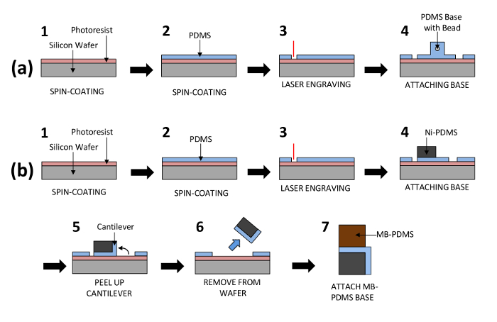
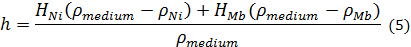
Figure 1: Process Flow for the Fabrication of the Biological Actuator and Biorobot. Each drawing represents the steps in the materials and methods in protocol sections 2 and 3 for biological actuator and biorobot fabrication. PDMS cantilevers are fabricated by spin-coating and laser engraving. Then the cantilevers are attached to a stationary base with a glass bead for the biological actuator (a) or to a self-stabilizing floating base for the biorobot (b). Please click here to view a larger version of this figure.
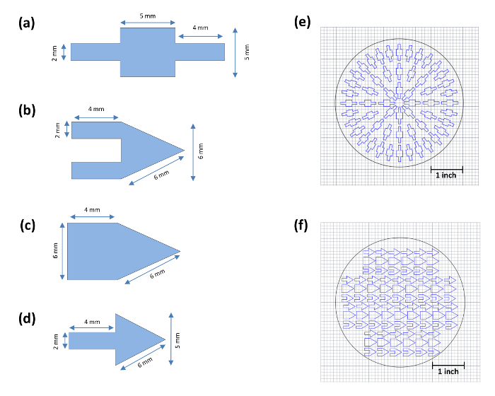
Figure 2: Dimensions of the Biological Actuator and Biorobots that are Fabricated in this Study and the CAD Files for Engraving Both the Biological Actuator and Various Types of Biorobots. (a) Biological actuator. (b) Double-arm cantilever biorobot. (c) Wide-arm cantilever biorobot. (d) Single-arm biorobot. (e) CAD drawing of biological actuator for laser engraving. (f) CAD drawing of biorobots for laser engraving. Please click here to view a larger version of this figure.
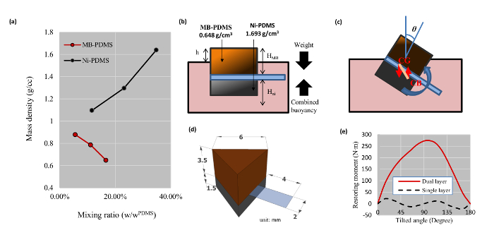
Figure 3: Mixing Densities for Ni-PDMS and MB-PDMS and Stability of the Biorobots. (a) Mixing ratios and resulting densities. (b) The densities and heights of the bases in relation to the media. (c) The rotation and restoration of the biorobot when tilted. The misalignment between the center of gravity (CG) and center of buoyancy (CB) generates a rotating moment. This moment will either restore the biorobot or cause it to tilt further. (d) The dimensions of the single arm biorobot in millimeter scale. (e) Restoring force was simulated for the single arm biorobot shown in part (c) under tilt conditions in (b) using two layers (Ni-PDMS and MB-PDMS) versus single layer (MB-PDMS). The graph shows that a single layer biorobot will not restore itself if it is tilted over 45°, whereas the dual layered biorobot will have always positive restoring force, keeping the biorobot upright. Please click here to view a larger version of this figure.
