In vivo Imaging of Biological Tissues with Combined Two-Photon Fluorescence and Stimulated Raman Scattering Microscopy
Summary
Stimulated Raman scattering (SRS) microscopy allows label-free imaging of biomolecules based on their intrinsic vibration of specific chemical bonds. In this protocol, the instrumental setup of an integrated SRS and two-photon fluorescence microscope is described to visualize cellular structures in the spinal cord of live mice.
Abstract
Stimulated Raman scattering (SRS) microscopy enables label-free imaging of the biological tissues in its natural microenvironment based on intrinsic molecular vibration, thus providing a perfect tool for in vivo study of biological processes at subcellular resolution. By integrating two-photon excited fluorescence (TPEF) imaging into the SRS microscope, the dual-modal in vivo imaging of tissues can acquire critical biochemical and biophysical information from multiple perspectives which helps understand the dynamic processes involved in cellular metabolism, immune response and tissue remodeling, etc. In this video protocol, the setup of a TPEF-SRS microscope system as well as the in vivo imaging method of the animal spinal cord is introduced. The spinal cord, as part of the central nervous system, plays a critical role in the communication between the brain and peripheral nervous system. Myelin sheath, abundant in phospholipids, surrounds and insulates the axon to permit saltatory conduction of action potentials. In vivo imaging of myelin sheaths in the spinal cord is important to study the progression of neurodegenerative diseases and spinal cord injury. The protocol also describes animal preparation and in vivo TPEF-SRS imaging methods to acquire high-resolution biological images.
Introduction
Raman microscopy1,2 is emerging as a powerful label-free method to image biological tissues based on the characteristic frequencies of various chemical bonds in biomolecules. Owing to its non-invasive and well-adaptive imaging capability, Raman microscopy has been widely used for imaging lipid-enriched components in biological tissues like myelin sheath3,4,5, adipocytes6,7, and lipid droplets8,9,10. Stimulated Raman scattering (SRS) signal acquired as stimulated Raman gain (SRG) or stimulated Raman loss (SRL) is background-free, showing perfect spectral resemblance to spontaneous Raman scattering11,12. In addition, SRL and SRG are linearly dependent on the analyte concentration, allowing for quantitative analysis of biochemical components9,11,13. Two-photon excited fluorescence microscopy (TPEF) has been widely used for in vivo biological imaging owing to its inherent optical sectioning capability, deep penetration depth, and low phototoxicity14,15,16. However, the performance of TPEF imaging depends on the characteristics of fluorescent tags, and the number of resolvable colors is limited due to the broadband fluorescence spectra8,17,18,19. Label-free SRS imaging and fluorescence-based TPEF imaging are two complementary imaging modalities, and their combination can provide abundant biophysical and biochemical information of tissues. These two imaging modalities are both based on the nonlinear optical (NLO) processes, which allows simple integration in one microscope system. The combination of the SRS and TPEF imaging, the so-called dual-modal imaging, enables high-dimensional imaging and profiling of cells and tissues, facilitating a comprehensive understanding of complex biological systems. Specifically, picosecond (ps) SRS microscopy can achieve chemical-bond imaging with high spectral resolution compared with femtosecond (fs) SRS technique11, allowing to differentiate multiple biochemical components in biological tissue, especially in the crowded fingerprint region20,21. In addition, compared with another commonly used dual-modal NLO microscope system with integration of coherent anti-Stokes scattering (CARS) microscope, SRS shows superior performance to CARS in terms of spectral and image interpretation as well as detection sensitivity11. The SRS-TPEF microscope has been used as a powerful tool to study various biological systems, such as Caenorhabditis elegans9,22, Xenopus laevis tadpole brain5, mouse brain23,24, spinal cord25,26, peripheral nerve27, and adipose tissue7, etc.
The spinal cord together with the brain makes up the central nervous system (CNS). Visualizing cellular activities in the CNS in vivo under physiological and pathological conditions is critical for understanding the mechanisms of CNS disorders28,29,30 and for developing corresponding therapies31,32,33. Myelin sheath, which wraps and insulates axons for high-speed action potential conduction, plays a significant role in the development of the CNS. Demyelination is thought of as a hallmark in white matter disorders, such as multiple sclerosis34. In addition, after spinal cord injury35, myelin debris can modulate macrophage activation, contributing to chronic inflammation and secondary injury36. Therefore, in vivo imaging of myelin sheath together with neurons and glial cells in living mouse models is of great help to understand the dynamic processes in CNS disorders.
In this protocol, the fundamental setup procedures of a home-built TPEF-SRS microscope are described and the dual-modal in vivo imaging methods for mouse spinal cord are introduced.
Protocol
All animal procedures performed in this work are conducted according to the guidelines of the Laboratory Animal Facility of the Hong Kong University of Science and Technology (HKUST) and have been approved by the Animal Ethics Committee of HKUST. Safety training for laser handling is required to set up and operate the TPEF-SRS microscope. Always wear laser safety goggles with appropriate wavelength range when dealing with laser.
1. Setup of the TPEF-SRS microscope (for setup schematic see Figure 1)
- Use an integrated optical parametric oscillator (OPO) connected with a mode-locked Ytterbium fiber laser as the ps laser source for SRS imaging.
NOTE: OPO outputs a Stokes beam (1031 nm) and a pump beam (tunable from 780 nm to 960 nm) with 2 ps pulse duration and 80 MHz repetition rate. The Stokes beam is modulated at 20 MHz by a built-in electro-optical modulator (EOM) for high-frequency phase-sensitive SRS detection at MHz level. - Use an fs titanium (Ti): sapphire laser as the laser source for TPEF imaging.
- Use a pair of lenses (L1 and L2) to collimate and adjust the size of the fs beam to 3 mm.
- Use a pair of lenses (L3 and L4) to collimate the ps laser beam and expand its diameter to 3 mm.
- Change the polarization of the fs laser beam from p polarization to s polarization using a half-wave plate.
- Combine the two laser beams with a polarizing beam splitter (PBS).
- Add a pair of 3 mm XY-scan galvanometer mirrors behind the PBS for beam scanning.
- Use a telecentric scan lens (L5) and an infinity-corrected tube lens (L6) to conjugate the scanning mirror and the rear pupil of the 25x objective lens. Expand the laser beam by the scan lens and tube lens to fill the back aperture of the objective.
- Place a PBS or dichroic mirror (D2) between the tube lens and objective lens for SRS or fluorescence signal collection. Use a motorized flipper to switch between PBS and D2.
NOTE: Part of the back-scattered SRS signal is lost when passing through the PBS as a result of its randomly shifted polarization. - Use a pair of lenses (L7 and L9) to narrow the detection beam and conjugate the rear pupil of the 25x objective lens with a photodiode sensor.
- Use a pair of lenses (L8 and L10) to narrow the detection beam and conjugate the rear pupil of the 25x objective with the detection surface of the photomultiplier (PMT).
- Use a dichroic mirror (D3) to separate the detection path of fluorescence and SRS signals.
- Place a filter set (Fs1) in front of the photodiode detector to block the Stokes laser and pass the pump beam only.
- Place a filter set (Fs2) in front of the PMT detector to pass the target fluorescence signal only.
- Connect the PMT to a current amplifier for signal amplification.
- Connect the photodiode to a lock-in amplifier.
- Connect the sync signal from the built-in EOM output to the reference input of the lock-in amplifier for SRS signal demodulation.
- Connect the PMT amplifier and lock-in amplifier outputs to the data acquisition module.
2. TPEF-SRS microscope system calibration
- Startup of the lasers
- Switch the key switch from Standby à On position to turn on the Ti: sapphire laser and wait for 30 min for the laser to warm up.
- Switch on the OPO by clicking on the Start button on the OPO control panel and wait for 20 min for the laser to warm up.
- After the ps laser warms up, use a high-speed photodetector to check the modulation depth of the Stokes beam. Open the laser shutter for the Stokes beam. Click on the Set OPO Power box and enter 20. Place the high-speed photodetector at the OPO output to detect the beam. Connect the output port of the photodetector to the input port of an oscilloscope using a coaxial cable with Bayonet Neill-Concelman (BNC) connector to monitor the laser pulse.
- Open the EOM Control window in the OPO control software. Adjust the EOM power and phase according to the pulse intensity diagram shown on the oscilloscope to achieve maximal modulation depth at 20 MHz.
NOTE: EOM performance is usually stable and only needs to be checked when the SRS signal is found significantly decreased.
- Optical alignment of the combined TPEF-SRS microscope
- Perform optical alignment for colocalization of the ps and fs beams as described in steps 2.2.2 to 2.2.13.
- Open the pump laser shutter while stopping the Stokes output in the OPO control software. Use OPO control software to set the wavelength of the pump beam to 796 nm by clicking the Set Signal box and entering the wavelength value 796. Click on the Set OPO Power box and enter 20 to set its power to the minimum (~20 mW) for optical alignment.
- Switch on the microscope computer and all associated electronic components, including scanners, objective actuators, photodiodes, PMTs, current amplifiers, lock-in amplifiers, and motorized flippers. Start the microscope control software.
NOTE: The microscope control software is a homemade interface. - Place two alignment plates (P1 and P2 in Figure 1) on the optical path. Place P1 behind PBS at a distance of about 10 cm and place P2 behind P1 at a distance of about 30 cm.
NOTE: The ps and fs beams are combined using a PBS (Figure 1). The two alignment plates are used to check the alignment as well as the colocalization of the two laser beams. - Open the microscope shutter for the ps laser beam.
- Adjust the mirror M1 to locate the ps laser beam center at the through-hole of P1. Use an infrared (IR) scope to observe the position of the beam spot at P1 when adjusting the mirror M1.
- Adjust the mirror M2 to locate the ps laser beam center at the through-hole of P2. Use the IR scope to observe the position of the beam spot at P2 when adjusting the mirror M2.
- Repeat steps 2.2.6 and 2.2.7 until the ps beam center locates at the through-hole of both alignment plates. Close the shutter of the ps beam in the microscope control software.
- Set the wavelength of fs Ti: sapphire laser at 740 nm and open the laser shutter. Set the laser power to 5 mW (measured at the input port of the microscope system) for optical alignment.
- Open the microscope shutter for the fs laser beam.
- Adjust the mirror M3 to locate the fs laser beam spot center at the through-hole of P1.
- Adjust the mirror M4 to locate the laser beam spot center at the through-hole of P2.
- Repeat steps 2.2.11 and 2.2.12 until the fs laser beam center locates at the through-holes of two alignment plates. Close the microscope shutter for the fs beam.
- Perform spatial overlapping of the pump and Stokes beams as described in steps 2.2.15 to 2.2.18.
NOTE: Although the pump and Stokes beams are roughly overlapped inside the ps laser, fine-tuning of the positions of the two laser beams is required to achieve optimal SRS performance. Since the pump beam is firstly aligned as previously described, next the Stokes beam is adjusted to colocalize with the pump beam. - Place a camera at the position of the objective to visualize the location of two beam spots. Mark the position of the pump beam on the camera screen as a reference.
- Place an alignment plate P0 before L3 (Figure 1). Use a hex key to adjust the optical mirror 1 (OM1) so that the Stokes beam center passes the through-hole of the alignment plate and colocalizes with the pump beam at the laser output port. Use the IR scope to confirm the position of the beam spot at P0 during adjustment.
NOTE: OM1 and OM2 are two mirrors in the OPO head to adjust the position of the 1031 nm Stokes beam. - Remove the alignment plate P0 and use the hex key to adjust the OM2 so that the center of the Stokes beam colocalizes with the reference mark of the pump beam on the camera.
- Repeat steps 2.2.16 and 2.2.17 until the Stokes beam strictly overlaps with the pump beam at both P0 and camera planes.
NOTE: When visualizing the beam spots on the camera, all the alignment plates should be removed from the optical path.
- Optimize imaging conditions
- Perform phase adjustment of the lock-in amplifier as described in steps 2.3.2. to 2.3.7.
NOTE: SRS detection is based on a high-frequency phase-sensitive scheme. For SRL detection, the intensity of the Stokes beam is modulated at 20 MHz and a lock-in amplifier is used to demodulate the signal. The phase and offset of the lock-in amplifier need to be adjusted to achieve the optimal image contrast. - Open the lock-in amplifier control software.
- Set the wavelength of the pump laser to 796 nm and the power of the pump and Stokes beam to be 15 mW and 25 mW on the sample, respectively.
NOTE: Here use olive oil for SRS imaging optimization and calibration. The Raman peak of olive oil at the carbon-hydrogen region is at 2863.5 cm-1, corresponding to the pump beam wavelength at 796 nm. - Seal the olive oil in a slide and attach a folded tissue paper to the bottom of the slide to enhance the signal backscattering for epi-SRS detection. Place the olive oil sample on the stage and adjust the focus of the 25x objective onto the sample.
- Use the microscope control software to set the imaging parameters as follows: 512 x 512 pixels for 500 μm x 500 μm field of view (FOV), 6.4 μs pixel dwell time. Use the lock-in amplifier control software to set the time constant value to be 10 μs, which is close to the pixel dwell time.
- Scan the laser beam over the sample. Use the lock-in amplifier control software to tune the phase (0-180°) with a step size of 22.5° until the SRS signal intensity reaches the maximum.
NOTE: In this all-analog lock-in amplifier, the signal output is the in-phase component, which is dependent on the phase of the reference signal. The phase can be adjusted by the lock-in amplifier control software with 11° resolution, allowing to maximize the detected signal to within ~2%12. The lock-in amplifier gets out of phase once the sync signal is disrupted. The phase needs to be readjusted every time the sync signal is reestablished. - Scan the sample with laser shutter closed. Use the lock-in amplifier control software to tune the offset value with a step size of 1 mV until the average SRS signal is close to zero.
NOTE: The average SRS signal is estimated as the average intensity of all pixels in the SRS image, which is calculated automatically by the microscope control software. Offsets are useful for canceling unwanted phase-coherent signals. - Perform temporal synchronization optimization as described in steps 2.3.9 to 2.3.14.
- Open the Delay Manager dialogue (Figure 2) in the OPO control software.
- Scan the olive oil and tune the delay stage until the olive oil SRS signal reaches its maximum.
NOTE: For the first time of SRS imaging, when the phase of the lock-in amplifier has not been optimized, temporal synchronization is first roughly adjusted to visualize the SRS signal of the sample before optimizing the phase of the lock-in amplifier. - Stop scanning and click on the Add Data button in the delay manager dialogue to record the current delay data.
- Repeat steps 2.3. 10 and 2.3.11 for different chemical samples at different wavelengths.
NOTE: Polystyrene beads, heavy water, 5-Ethynyl-2′-deoxyuridine, glycerol are used to measure the delay data at different vibrational bands. - Select the Data Fit and Order 5 on the delay manager dialogue to fit the current data points with the fifth-order polynomic function. Apply the fitted data by clicking on the Use As Custom button and checking the check box. The delay stage will be auto-adjusted at different wavelengths according to the fitted delay curve.
- Save all the delay data in a text file, which can be loaded for future use.
- Perform phase adjustment of the lock-in amplifier as described in steps 2.3.2. to 2.3.7.
3. Surgical preparation of mouse for in vivo fluorescence and SRS imaging
- Sterilize all required tools, including scalpels, spring scissors, forceps, coverslips, and gauze pads.
- Disinfect all the surfaces, which would be touched during surgery with 70% ethanol. Cover the working area of the benchtop with sterile drapes. Put a heating pad under the drape.
- Use Thy1-YFP-H (Tg(Thy1-YFP)HJrs/J)37 transgenic mice that express enhanced yellow fluorescence protein (EYFP) in dorsal root ganglion afferent neurons for in vivo spinal cord imaging. Weigh the mouse and induce anesthetization by intraperitoneal (i.p.) injection of the ketamine-xylazine mixture (87.5 mg kg-1 and 12.5 mg kg-1).
- Pinch the toe of the mouse to ensure deep anesthesia. Supplement with half the original dose of the anesthetics if needed. Apply ointment to the mouse eyes to prevent corneal dryness.
- Shave the hair on the back above the thoracic spine, and then completely remove the hair using depilating cream. Disinfect the shaved area with iodine solution.
- Make a small midline incision (~1.5 cm) of the skin over the T11-T13 vertebra with a scalpel.
- Incise muscles and tendons both on top and on sides of the T11-T13 vertebra with spring scissors and forceps. Expose the three adjacent vertebras. Use sterile gauze pads and sterile saline to control bleeding and clean the surgical site.
- Stabilize the spine with the help of the two stainless steel sidebars on a custom-designed stabilization stage (Figure 2B).
- Use a #2 forcep to perform a laminectomy at T12. Carefully use the forcep to break the lamina piece by piece until the whole lamina of the T12 vertebra is removed.
- Wash away the blood overlying the spinal cord with sterile saline and use the gauze pad to absorb excessive fluid. Apply pressure on the bleeding site with a piece of gauze pad to control bleeding.
- Place a coverslip (22 x 22 mm) on the clamping bar and fill the interspace between the coverslip and the spinal cord with saline.
4. In vivo TPEF-SRS imaging of mouse spinal cord
- Mount the stabilization stage on a five-axis stage beneath the TPEF-SRS microscope.
NOTE: The five-axis stage allows three-axis translation and ±5° pitch and roll flexure motion. - Secure the mouse head with two head bars and lower the holding plate to offer enough space for chest movement during breathing, alleviating motion artifacts.
- Insert a heating pad under the mouse to keep the mouse warm during imaging.
- Adjust the z translational stage to tune the focus until the bright-field image of spinal cord vasculature can be observed under a 10x objective.
- Locate the spinal cord dorsal vein at the center of the FOV by tuning the two-axis translational stage of the five-axis stage.
- Tune the roll and pitch angles of the five-axis stage to adjust the spinal cord dorsal surface perpendicular to the objective axis based on the bright-field image.
- Replace the 10x with a 25x water immersion objective for TPEF-SRS imaging.
- Set the wavelength of the fs beam to 920 nm. Tune the fs beam power to be 10 mW on the sample.
- Set the wavelength of the pump beam to 796 nm. Tune the power of the pump and Stokes beam to be 60 mW and 75 mW on the sample, respectively.
NOTE: Spinal cord SRS imaging is performed at the wavenumber of 2863.5 cm-1, which corresponds to the Raman peak of myelin sheaths at the carbon-hydrogen region based on the measured SRS spectra7,9. The laser power is determined to ensure high-resolution TPEF-SRS imaging of the spinal cord. Tissue damage is not observed under the current imaging conditions. - For SRS imaging, select PBS above the objective using a motorized flipper by pressing the Switch button connected to the motorized flipper.
- Set the imaging parameters as follows: 512 x 512 pixels for 150 μm x 150 μm FOV, 3.2 μs pixel dwell time, 2 μs time constant.
- Start scanning the sample and set the focus on the dorsal surface of the spinal cord.
- Finely tune the delay stage by the OPO control software until maximum spinal cord SRS signal is achieved.
NOTE: Biological samples can induce extra chromatic dispersion, the delay stage may require to be adjusted to optimize the temporal synchronization. However, when SRS imaging is performed near the tissue top surface, the temporal difference of the two laser pulses introduced by the biological tissue and the imaging window is usually small (less than several hundred fs). - For TPEF imaging, select dichroic mirror D2 above the objective using a motorized flipper by pressing the Switch button connected to the motorized flipper.
- Set the imaging parameters and start scanning the sample. To capture the TPEF-SRS image stack, acquire the TPEF and SRS images sequentially with a 1 s interval at the same depth before going to the next depth. The imaging parameters for TPEF imaging are 512 x 512 pixels, 150 μm x 150 μm FOV, 3.2 μs pixel dwell time.
- Remove the animal from the stabilization stage after all images are collected.
- Clean the exposed tissue by flushing saline and absorb the excess fluid using a gauze pad. Apply silicone gel on the exposed spinal cord and wait for ~5 min until it gets cured.
- Suture the skin with #6-0 surgical suture to close the wound. Apply burn cream on the skin of the surgical site to prevent infection. Administer analgesic treatment subcutaneously (0.1 mg/kg buprenorphine).
- Place the animal in a clean cage and place the cage on a heating pad until the mouse fully recovers from anesthesia.
- Repeat analgesic administration every 12 hours for 3 days after surgery.
- Close the shutter of OPO and fs laser. Set the power of the pump and Stokes beam to the maximum.
NOTE: Setting maximal power before turning off the laser is beneficial for laser maintenance. - Set the wavelength of the pump beam and fs laser to 800 nm.
- Set the two lasers on standby, close all the electronics control software and turn off all the associated equipment.
Representative Results
In vivo dual-modal imaging of spinal axons as well as myelin sheaths is conducted using the Thy1-YFPH transgenic mice, which express EYFP in dorsal root ganglion afferent neurons (Figure 3). These labeled afferent neurons relay the sensory information from the peripheral nerve to the spinal cord, with the central branch located in the spinal cord dorsal column. With the TPEF-SRS microscope, densely distributed myelin sheath can be clearly visualized using label-free SRS imaging, and sparsely labeled YFP axons can be observed using TPEF imaging. It is revealed by the dual-model imaging that axons are closely wrapped by a thick layer of myelin sheaths (Figure 3C). Nodes of Ranvier (NR), where the axolemma is bare of the myelin sheath, play an essential role in the fast saltatory propagation of action potentials. As can be seen in the TPEF-SRS spinal cord image (Figure 3C), NR show decreased axonal diameter and axolemma directly exposed to the extracellular matrix. It is essential to image the axons together with the surrounding myelin sheaths to confirm the existence and location of NR. Therefore, TPEF-SRS microscopy allows us to observe the dynamic changes of axons and myelin sheaths in the development of spinal cord disorders, which is significant to understand the mechanisms of cellular dynamics.
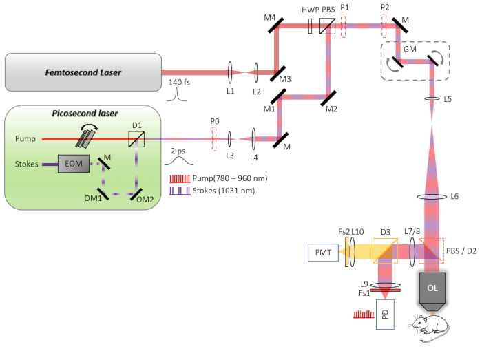
Figure 1: The schematic diagram of the TPEF-SRS microscope system. The pump and Stokes beams are combined with a dichroic mirror (D1) in the picosecond (ps) laser. The ps beam and femtosecond (fs) beam are collimated and expanded/narrowed by a pair of lenses (L3, L4, and L1, L2, respectively) to match the 3 mm XY-scan galvanometer mirrors. The fs beam is rotated from horizontal to vertical polarization by a half-wave plate (HWP), and then combined with the ps beam by a polarizing beam splitter (PBS). The scanning mirrors and the rear pupil of the objective lens are conjugated by a telecentric scan lens L5 and an infinity-corrected tube lens L6. The laser beam is expanded by the scan and tube lens to fill the back aperture of the 25x objective. For stimulated Raman scattering (SRS) imaging, the backscattered pump beam collected by the objective is reflected by a PBS and directed to a large area (10 mm x 10 mm) silicon photodiode (PD). For two-photon imaging, the two-photon excited fluorescence (TPEF) signal is reflected by a dichroic beam splitter D2 to the photodetection unit. A current photomultiplier (PMT) module is used to detect the TPEF signal. Abbreviations-L1-L10: lenses; OL: objective lens; D1-D3: dichroic mirrors; Fs1, Fs2: filter sets; M: mirrors; OM1, OM2: optical mirrors; P0-P2: alignment plates. Please click here to view a larger version of this figure.
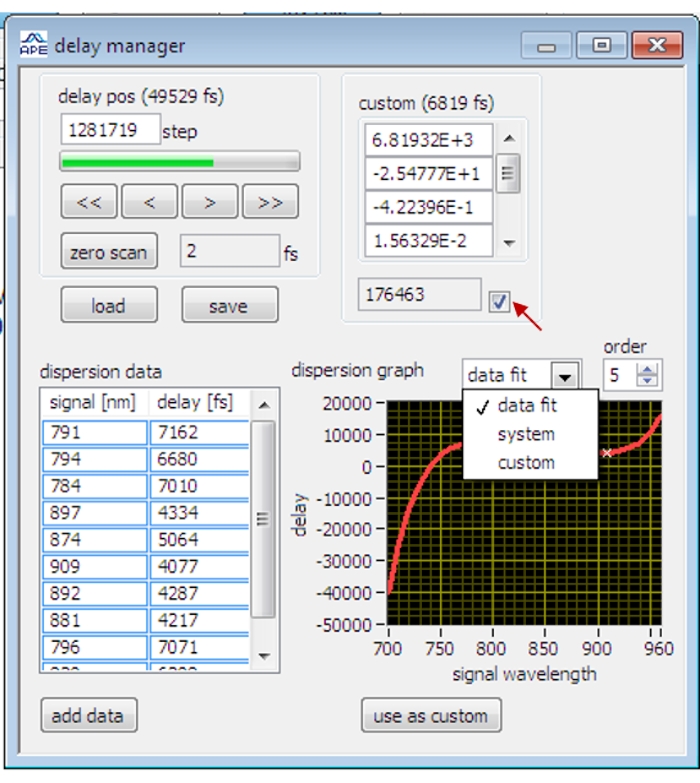
Figure 2: The interface of the delay manager on the OPO control software. The red arrow indicates the checking box for applying the calibrated delay data. Please click here to view a larger version of this figure.
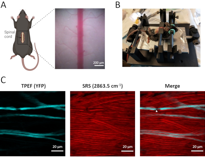
Figure 3: In vivo TPEF-SRS imaging of mouse spinal cord. (A) Schematic diagram of the surgical preparation of the mouse spinal cord and the bright-field image of the spinal cord. (B) Mouse mounting scheme for in vivo imaging of the spinal cord. (C) Maximal z projection images of axons and myelin sheaths in mouse spinal cord. White arrowheads indicate the location of a node of Ranvier. SRS images of myelin are taken at the Raman shift of 2863.5 cm-1. Figure A was created using BioRender (https://biorender.com/). Please click here to view a larger version of this figure.
Discussion
In this protocol, the basic setup of the TPEF-SRS microscope is described in detail. For SRS imaging, the pump and Stokes beams are temporally and spatially overlapped inside the OPO. However, this overlapping can be disrupted after passing through the microscope system. Therefore, both spatial and temporal optimization of the colocalization of the pump and Stokes beams is necessary and critical to achieving optimal SRS imaging. The temporal delay between the pump and Stokes beam is related to the optical path difference of the two beams, which is determined by the dispersion of optical elements in the microscope system38. When the wavelength of the pump beam is tuned for SRS imaging at different Raman shifts, the optical path length of the pump beam changes accordingly because the refractive index of the optical lenses is dependent on the wavelength38. Therefore, the temporal delay between the pump and Stokes laser pulse changes with the wavelength of the pump beam and thus needs to be calibrated. The OPO is equipped with a software-controlled delay line for temporal synchronization of the pump and Stokes beam. For the same optical setup, the delay data remains stable and only needs to be calibrated once. As a result, the delay data at different wavelengths of the pump beam can be saved at the first measurement for future use. The calibrated delay data can be applied automatically by the OPO control software when the wavelength of the pump beam is changed, which is convenient for SRS imaging at different Raman shifts or hyperspectral SRS imaging. For TPEF-SRS imaging, strict spatial overlapping of the ps and fs beams after the combination is a critical step to avoid any FOV shift between the two imaging models. Firstly, the ps pump beam and fs beam are aligned to make sure they are both on the optical axis of the microscope system, which is critical to avoid any FOV shift when switching the two imaging models. Then, using the pump beam as a reference, the Stokes beam position is adjusted accordingly to achieve strict spatial colocalization. Each alignment procedure requires several trials to reach the optimum.
If the SRS signal significantly decreases, the phase value of the lock-in amplifier and time-delay data should be checked first. Since the lock-in amplifier gets out of phase once the sync signal is disrupted, the phase value requires readjusting every time after its power supply or EOM sync signal is interrupted. The temporal synchronization of the pump and Stokes beam can be quickly checked by slightly adjusting the delay line inside the OPO. If the calibrated time-delay data is far away from the optimal value, a zero scan should be performed to recalibrate the delay offset by clicking the Zero Scan button on the delay manager dialogue. The whole zero scan procedure takes about 10 min. If the SRS signal fails to recover after optimization of the phase and time-delay value, the EOM modulation of the Stokes beam should be checked as described in steps 2.1.3-2.1.4. If the extinction ratio is far less than 10 dB with the observation of small pulse peaks at the off position of the Stokes pulse train, the EOM should be restarted, and the modulation power and phase should be readjusted to achieve maximal modulation depth. Usually, the modulation problem can be solved by resetting the EOM. If not, technical support from the manufacturer should be required.
For in vivo thick tissue imaging, epi-SRS detection mode has to be used. In this protocol, a PBS is used to pass the excitation laser and reflect the back-scattered SRS signal to the detector. The detected SRL signal is dependent on the backscattering of the forward-going pump beam by tissues. The excitation lasers have linear polarization and can fully pass through the PBS, while the backscattered beam has shifted polarization and can thus only be partially reflected by the PBS. Therefore, the current signal collection scheme shows lower efficiency compared to the strategy that directly places an annular photodetector in front of the objective12. Nevertheless, due to the strong scattering of the lipid-rich tissues39, high signal-to-noise ratio SRS images (512 x 512 pixels) of the spinal cord can be acquired with 1-2 s integration time, making this PBS-based collection scheme an appropriate approach for spinal cord imaging. On the other hand, however, the strong tissue scattering limits light penetration depth. For both SRS and TPEF imaging, the imaging depth for the spinal cord is limited to about 50 μm.
The sequential imaging procedure for SRS and TPEF imaging is the major limitation of the current dual-modal imaging method. In the protocol, TPEF and SRS imaging are performed at the same location sequentially with a 1 s interval by switching the motorized flipper automatically. Motion artifacts may cause an imperfect merge of the TPEF and SRS images, which limits the capability of this method for imaging highly dynamic processes or tissues largely affected by the breath and heartbeat of animals. One possible solution is to collect the ps laser-excited two-photon fluorescence simultaneously during SRS imaging9. However, this method is only applicable to the biological structures with strong fluorescence signals, since the ps pulse has a much lower fluorescence excitation efficiency compared to the fs pulse14. Alternatively, the problem can be solved by using an fs-SRS system22,40, where the fs laser source allows simultaneous excitation of the SRS and TPEF signals effectively, at the expense of low spectral resolution of the SRS imaging. Another solution is to use the ps laser-excited fluorescence obtained during SRS imaging as a reference to register the fs fluorescence images. As shown in Figure 3, this registration strategy works well if no significant motion occurs during the SRS and fluorescence imaging.
SRS exhibits unique advantages in biological imaging since it provides chemical information of biomolecules based on its specific label-free contrast mechanism41. Compared with CARS which has also been combined with TPEF for multimodal NLO imaging, SRS showed better spectral and image interpretation capability11. Therefore, it has been widely applied for imaging lipid9,11, protein42,43, DNA44, and bio-orthogonal components containing alkyne (C ≡ C)13,45, carbon−deuterium (C−D)9,46 and oxygen-deuterium (O-D) bonds47,48 in biological tissues. In this protocol, we used a ps laser source for SRS imaging and a fs laser source for TPEF imaging, which combines the advantages of efficient fluorescence excitation and high Raman spectral resolution, allowing effective differentiation of diverse biomolecules42,44. In the spinal cord, complex cell-microenvironment interactions involving glial cells, neurons, and recruited immune cells contribute to the progression of injury49 and diseases50. Combined with various fluorescence and SRS imaging probes, TPEF-SRS microscopy can achieve simultaneous imaging of various cellular structures as well as their distinct biomolecule components, which can significantly facilitate our understanding of the onset and development of spinal cord disorders.
Divulgations
The authors have nothing to disclose.
Acknowledgements
This work was supported by the Hong Kong Research Grants Council through grants 16103215, 16148816, 16102518, 16102920, T13-607/12R, T13-706/11-1, T13-605/18W, C6002-17GF, C6001-19E, N_HKUST603/19, the Innovation and Technology Commission (ITCPD/17-9), the Area of Excellence Scheme of the University Grants Committee (AoE/M-604/16, AOE/M-09/12), and the Hong Kong University of Science & Technology (HKUST) through grant RPC10EG33.
Materials
| #2 Forceps | Dumont | 11223-20 | For laminectomy |
| 10X objective | Nikon | CFI Plan Apo Lambda 10X | |
| 25X objective | Olympus | XLPLN25XSVMP2 | |
| Burn cream | Betadine | ||
| Camera | Sony | α6300 | |
| Current amplifier | Stanford research | SR570 | |
| Current photomultiplier modules | Hamamatsu | H11461-01 | |
| D2 665 nm long-pass dichroic mirror | Semrock | FF665-Di02-25×36 | For directing epi-fluorescence signal to the detection module |
| D3 700 nm short-pass dichroic mirror | Edmund | 69-206 | For separating SRS from TPEF detection path |
| Depilating cream | Veet | ||
| FS1 975 nm short-pass filter | Edmund | 86-108 | For blocking stokes beam |
| FS1 Bandpass filter | Semrock | FF01-850/310 | For blocking stokes beam |
| Fs2 Bandpass filter | Semrock | FF01-525/50 | For selecting YFP signal |
| Fs2 Shortpass filter | Semrock | FF01-715/SP-25 | For blocking fs excitation laser beam |
| Half-wave plate | Thorlabs | SAHWP05M-1700 | |
| High-speed photodetector | MenloSystems | FPD 310-F | For checking Stokes beam modulation |
| Iodine | Betadine | ||
| IR Scope | FJW | FIND-R-SCOPE Infrared Viewer 2X Kit Model 84499C2X | |
| Iris | Thorlabs | CPA1 | |
| L1 | Thorlabs | AC254-060-B-ML | |
| L10 | Thorlabs | LA4052-A | |
| L2 | Thorlabs | LA1422-B | |
| L3 | Thorlabs | AC254-050-B | |
| L4 | Thorlabs | AC254-060-B-ML | |
| L7 | f=100 mm, AB coating | ||
| L8 | Thorlabs | LA4874-A | |
| L9 | Thorlabs | AC254-035-B-ML | |
| Lock-in amplifier | APE | ||
| Mirror | Thorlabs | PF10-03-P01 | |
| Motorized flipper | Thorlabs | MFF101/M | |
| multifunctional acquisition card | National Instrument | PCIe-6363 | |
| Oscilloscope | Tektronix | TDS2012C | |
| Photodiode | APE | For detecting SRS signal | |
| Picosecond laser source | APE | picoEmerald | |
| Polarizing beam splitter | Thorlabs | CCM1-PBS252/M | |
| Power meter | Newport | 843-R | |
| Saline | Braun | ||
| Scan lens L5 | Thorlabs | SL50-CLS2 | |
| Scanning mirror | Cambridge Technology | 6215H | |
| Silicone gel | World Precision Inc. | KWIK-SIL | |
| Ti:sapphire fs laser | Coherent | Chameleon Ultra II | |
| Tube lens L6 | Thorlabs | TTL200-S8 |
References
- Raman, C. V., Krishnan, K. S. The optical analogue of the compton effect. Nature. 121 (3053), 711 (1928).
- Turrell, G., Corset, J. . Raman Microscopy: Developments and Applications. , (1996).
- Tian, F., et al. Monitoring peripheral nerve degeneration in ALS by label-free stimulated Raman scattering imaging. Nature Communications. 7 (1), 13283 (2016).
- Shi, Y., et al. Longitudinal in vivo coherent anti-Stokes Raman scattering imaging of demyelination and remyelination in injured spinal cord. Journal of Biomedical Optics. 16 (10), 106012 (2011).
- Hu, C. R., Zhang, D., Slipchenko, M. N., Cheng, J. -. X., Hu, B. Label-free real-time imaging of myelination in the Xenopus laevis tadpole by in vivo Stimulated Raman Scattering Microscopy. Journal of Biomedical Optics. 19 (8), 086005 (2014).
- Den Broeder, M. J., et al. Altered adipogenesis in Zebrafish larvae following high fat diet and chemical exposure is visualised by Stimulated Raman Scattering Microscopy. International Journal of Molecular Sciences. 18 (4), 894 (2017).
- He, S., et al. In vivo metabolic imaging and monitoring of brown and beige fat. Journal of Biophotonics. 11 (8), (2018).
- Wang, M. C., Min, W., Freudiger, C. W., Ruvkun, G., Xie, X. S. RNAi screening for fat regulatory genes with SRS microscopy. Nature Methods. 8 (2), 135-138 (2011).
- Li, X., et al. Quantitative imaging of lipid synthesis and lipolysis dynamics in Caenorhabditis elegans by Stimulated Raman Scattering Microscopy. Analytical Chemistry. 91 (3), 2279-2287 (2019).
- Zhang, C., Li, J., Lan, L., Cheng, J. -. X. Quantification of lipid metabolism in living cells through the dynamics of lipid droplets measured by Stimulated Raman Scattering Imaging. Analytical Chemistry. 89 (8), 4502-4507 (2017).
- Freudiger, C. W., et al. Label-free biomedical imaging with high sensitivity by Stimulated Raman Scattering Microscopy. Science. 322 (5909), 1857-1861 (2008).
- Saar, B. G., et al. Video-rate molecular imaging in vivo with Stimulated Raman Scattering. Science. 330 (6009), 1368-1370 (2010).
- Li, X., Jiang, M., Lam, J. W. Y., Tang, B. Z., Qu, J. Y. Mitochondrial imaging with combined fluorescence and Stimulated Raman Scattering Microscopy using a probe of the aggregation-induced emission characteristic. Journal of the American Chemical Society. 139 (47), 17022-17030 (2017).
- Helmchen, F., Denk, W. Deep tissue two-photon microscopy. Nature Methods. 2 (12), 932-940 (2005).
- Pawlicki, M., Collins, H. A., Denning, R. G., Anderson, H. L. Two-photon absorption and the design of two-photon dyes. Angewandte Chemie International Edition. 48 (18), 3244-3266 (2009).
- König, K. Multiphoton microscopy in life sciences. Journal of Microscopy. 200 (2), 83-104 (2000).
- Dean, K. M., Palmer, A. E. Advances in fluorescence labeling strategies for dynamic cellular imaging. Nature Chemical Biology. 10 (7), 512-523 (2014).
- Tsurui, H., et al. Seven-color fluorescence imaging of tissue samples based on fourier spectroscopy and singular value decomposition. Journal of Histochemistry & Cytochemistry. 48 (5), 653-662 (2000).
- Niehörster, T., et al. Multi-target spectrally resolved fluorescence lifetime imaging microscopy. Nature Methods. 13 (3), 257-262 (2016).
- Zhang, X., et al. Label-free live cell imaging of nucleic acids using Stimulated Raman Scattering (SRS) Microscopy. Chemphyschem: A European Journal of Chemical Physics and Physical Chemistry. 13 (4), 1054-1059 (2012).
- Ji, M., et al. Label-free imaging of amyloid plaques in Alzheimer’s disease with stimulated Raman scattering microscopy. Science Advances. 4 (11), 7715 (2018).
- Li, X., et al. Integrated femtosecond stimulated Raman scattering and two-photon fluorescence imaging of subcellular lipid and vesicular structures. Journal of Biomedical Optics. 20 (11), 110501 (2015).
- Imitola, J., et al. Multimodal coherent anti-Stokes Raman scattering microscopy reveals microglia-associated myelin and axonal dysfunction in multiple sclerosis-like lesions in mice. Journal of Biomedical Optics. 16 (2), 021109 (2011).
- Uckermann, O., et al. Label-free multiphoton microscopy reveals altered tissue architecture in hippocampal sclerosis. Epilepsia. 58 (1), 1-5 (2017).
- Tamosaityte, S., et al. Inflammation-related alterations of lipids after spinal cord injury revealed by Raman spectroscopy. Journal of Biomedical Optics. 21 (6), 061008 (2016).
- Uckermann, O., et al. Endogenous two-photon excited fluorescence provides label-free visualization of the inflammatory response in the rodent spinal cord. BioMed Research International. 2015, 859084 (2015).
- van Hameren, G., et al. In vivo real-time dynamics of ATP and ROS production in axonal mitochondria show decoupling in mouse models of peripheral neuropathies. Acta Neuropathologica Communications. 7 (1), 1-16 (2019).
- Davalos, D., et al. Fibrinogen-induced perivascular microglial clustering is required for the development of axonal damage in neuroinflammation. Nature Communications. 3 (1), 1-15 (2012).
- Ylera, B., et al. Chronically CNS-injured adult sensory neurons gain regenerative competence upon a lesion of their peripheral axon. Current Biology. 19 (11), 930-936 (2009).
- Wake, H., Moorhouse, A. J., Jinno, S., Kohsaka, S., Nabekura, J. Resting microglia directly monitor the functional state of synapses in vivo and determine the fate of ischemic terminals. Journal of Neuroscience. 29 (13), 3974-3980 (2009).
- Lau, S. -. F., et al. IL-33-PU.1 transcriptome reprogramming drives functional state transition and clearance activity of microglia in Alzheimer’s Disease. Cell Reports. 31 (3), 107530 (2020).
- Tang, P., et al. In vivo two-photon imaging of axonal dieback, blood flow, and calcium influx with methylprednisolone therapy after spinal cord injury. Scientific Reports. 5, 9691 (2015).
- Yang, Z., Xie, W., Ju, F., Khan, A., Zhang, S. In vivo two-photon imaging reveals a role of progesterone in reducing axonal dieback after spinal cord injury in mice. Neuropharmacology. 116, 30-37 (2017).
- Dobson, R., Giovannoni, G. Multiple sclerosis – a review. European Journal of Neurology. 26 (1), 27-40 (2019).
- Totoiu, M. O., Keirstead, H. S. Spinal cord injury is accompanied by chronic progressive demyelination. Journal of Comparative Neurology. 486 (4), 373-383 (2005).
- Kopper, T. J., Gensel, J. C. Myelin as an inflammatory mediator: Myelin interactions with complement, macrophages, and microglia in spinal cord injury. Journal of Neuroscience Research. 96 (6), 969-977 (2018).
- Feng, G., et al. Imaging neuronal subsets in transgenic mice expressing multiple spectral variants of GFP. Neuron. 28 (1), 41-51 (2000).
- Pedrotti, F. L., Pedrotti, L. M., Pedrotti, L. S. . Introduction to Optics. , (2017).
- Jacques, S. L. Optical properties of biological tissues: a review. Physics in Medicine and Biology. 58 (11), 37-61 (2013).
- Zhang, D., Slipchenko, M. N., Cheng, J. -. X. Highly sensitive vibrational imaging by Femtosecond Pulse Stimulated Raman Loss. The Journal of Physical Chemistry Letters. 2 (11), 1248-1253 (2011).
- Hu, F., Shi, L., Min, W. Biological imaging of chemical bonds by stimulated Raman scattering microscopy. Nature Methods. 16 (9), 830-842 (2019).
- Ji, M., et al. Rapid, label-free detection of brain tumors with Stimulated Raman Scattering Microscopy. Science Translational Medicine. 5 (201), (2013).
- Freudiger, C. W., et al. Multicolored stain-free histopathology with coherent Raman imaging. Laboratory Investigation. 92 (10), 1492-1502 (2012).
- Lu, F. K., et al. Label-free DNA imaging in vivo with stimulated Raman scattering microscopy. Proceedings of the National Academy of Sciences of the United States of America. 112 (37), 11624-11629 (2015).
- Yamakoshi, H., et al. Imaging of EdU, an Alkyne-tagged cell proliferation probe, by Raman Microscopy. Journal of the American Chemical Society. 133 (16), 6102-6105 (2011).
- van Manen, H. -. J., Lenferink, A., Otto, C. Noninvasive imaging of protein metabolic labeling in single human cells using stable isotopes and Raman Microscopy. Analytical Chemistry. 80 (24), 9576-9582 (2008).
- Zhang, L., et al. Spectral tracing of deuterium for imaging glucose metabolism. Nature Biomedical Engineering. 3 (5), 402-413 (2019).
- Shi, L., et al. Optical imaging of metabolic dynamics in animals. Nature Communications. 9 (1), 2995 (2018).
- Ahuja, C. S., et al. Traumatic spinal cord injury. Nature Reviews Disease Primers. 3 (1), 1-21 (2017).
- Lassmann, H. Multiple sclerosis pathology. Cold Spring Harbor Perspectives in Medicine. 8 (3), 028936 (2018).
