We have performed the OTM surgery on 11 adult male mice (C57/BL6, 3 months old). They were euthanized for results on days 3, 8, and 14 post surgery. In these experiments, the right maxillary side is the operation side, while the left maxillary side is the control side. The micro-CT showed that there was a temporal consecutive increase in the distance between M1 and M2: 30 µm, 70 µm, and 110 µm at days 3, 8, and 14 post surgery, respectively (Figure 4). The low-density periodontal ligament showed broadening at the distal side and narrowing at the mesial side of roots as a result of the mechanical load (Figure 5). Further, the periodontal ligament was continuous and there was no absorption occurring in any root. These results prove that it is feasible and safe to move the M1 physically with this protocol.
Furthermore, we have analyzed the bone area enclosed within the roots of M1 with parameters shown in Figure 6. The percentage of bone volume and bone mineral density of the operation side on day 8 showed a significant decrease compared with the control side (Figure 6A,B). In contrast, the percent bone volume of the operation side on days 3 and 14 showed a significant increase compared with the operation side on day 8 (Figure 6A). These results suggest that bone remodeling is inactive before day 3 post surgery. After day 3 post surgery, bone absorption starts to dominate the bone remodeling process. After day 8 post surgery, bone formation gains an edge in bone remodeling and the alveolar bone almost returns to the physiological level, which also implies that tooth movement almost comes to a stop. By day 14 of this protocol, the bone remodeling enclosed within the roots of M1 goes through three stages, which can roughly be divided into the preparation, bone resorption, and bone formation stages. Researchers can thus study different stages of bone remodeling with this model.
Figure 7 shows the results of hematoxylin-eosin staining and Masson-trichrome staining. We chose the alveolar bone between the mesial buccal root (MB) and the distal buccal root (DB) of M1 as the region of interest. The periodontal ligaments at the distal end of the MB and the mesial end of the DB are the fronts of force transmission of the bone region of interest. The control side of each group showed a similar manifestation: These periodontal ligaments shared a similar width with wave-like fiber and spindle-shaped cells in alignment, and the surface of the alveolar bone was intact linear. This suggests that the periodontal tissues enclosed within the roots of M1 were not subjected to unbalanced and excessive mechanical load under physiological conditions.
On day 3 post surgery, the periodontal ligament fiber was stretched tightly at the tension side, while the periodontal ligament fiber was compressed with morphological ambiguity. Hyalinization was noted in the area of greatest pressure. The surface of the alveolar bone had still retained its integrity on both sides. Consistent with the micro-CT results, in the initial 3 days post surgery, M1 moved within the alveolar socket by compressing the periodontal ligament on the pressure side, while bone resorption or formation was not yet observed.
On day 8 post surgery, the periodontal ligaments on both sides showed the same features as those on day 3 although the surface of the alveolar bone had begun to look rough. Moreover, the marrow cavity was enlarged and the number of trabecular bones seemed to reduce as seen in the CT data. Therefore, on day 8 post surgery, the histopathological phenotype of bone remodeling shows an increase in bone resorption. The alveolar bone also indicates that M1 moves at a high speed.
On day 14 post surgery, the widths of the periodontal ligaments on both sides seemed to be almost equal. The surface of the alveolar bone had become much rougher compared with that on day 8 post surgery. However, the bone was restored to the physiological level on the control side, which was also indicated by the CT data. This stage shows that bone formation dominated the bone modeling process. As the mechanical load was applied only once at the time of the operation, the load decreased as the moving distance increased. As the alveolar bone returned to normal, the movement of M1 also stopped.
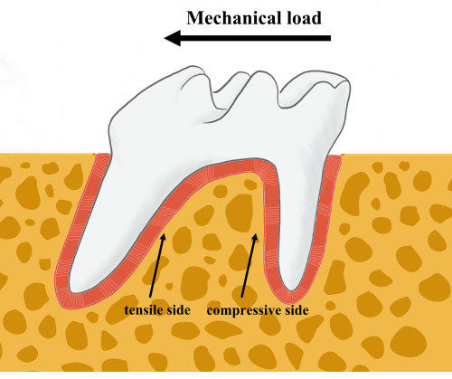
Figure 1: Schematic representation of tooth movement. When a mechanical load is applied to the molar, the tensile and compressive sides of the alveolar bone remodeling can be defined. The thick arrow indicates the direction of the mechanical load. Thin arrows indicate the tensile and the compressive sides of the bone remodeling front. Please click here to view a larger version of this figure.
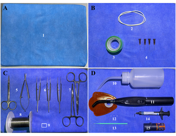
Figure 2: Surgical items. (A) (1) Surgical platform: a foam board or corkboard wrapped in medical non-woven fabric. (B) Fasteners: (2) two rubber bands, (3) tape, and (4) four 27 G needles. (C) Surgical instruments and orthodontic supplies: (5) surgical scissors, (6) ophthalmic tweezers, (7) needle holders, (8) 304 stainless steel wire, and (9) a customized coil spring. The white rectangle refers to the customized coil spring. Enlarged versions of the spring with and without force are shown in Supplementary Figure S1. (D) Dental restoration supplies: (10) air pump bottle, (11) light curer, (12) cotton balls, (13) cotton sticks, (14) light-cured fluid resin, and (15) adhesives. Please click here to view a larger version of this figure.
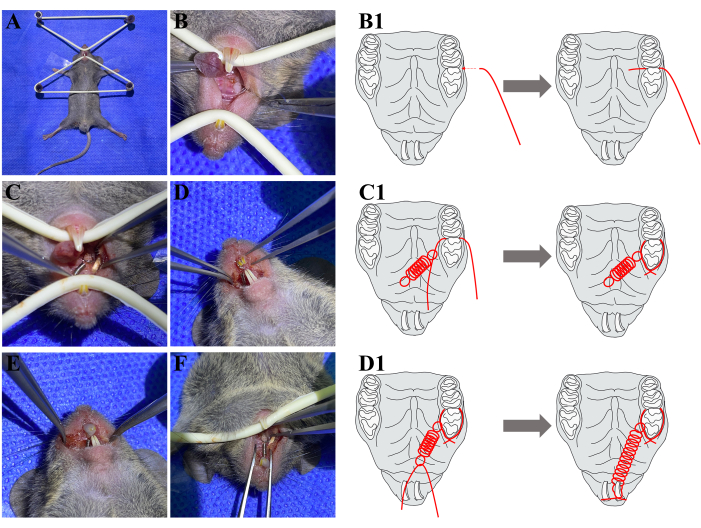
Figure 3: Surgical process. (A) Fasten the mouse to the surgical platform. (B) Push the 304 stainless steel wire through the interproximate space between M1 and M2 from the buccal side. (B1) A schematic diagram has been added to help understanding. (C) A coil spring is fastened to M1 and no occlusal interference occurs at M1. (C1) A schematic diagram has been added to help understanding. (D) The other end of the coil spring is fastened to the ipsilateral upper incisor. (D1) A schematic diagram has been added to help understanding. (E) Apply fluid resin to wrap the incisors and stainless steel together. (F) The final view of all the orthodontic appliances. Abbreviations: M1 = the maxillary first molar; M2 = the maxillary second molar. Please click here to view a larger version of this figure.
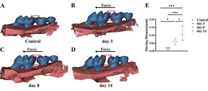
Figure 4: Representative micro-CT three-dimensional images and statistical analysis of different stages of M1 movement. (A) Under physiological circumstances, there is no space between M1 and M2. (B–D) M1 starts to move and the moving distance increases according to the mutual positional relationship between M1 and M2 over time. The red box refers to the distance between M1 and M2. The black arrow refers to the direction of the mechanical load. (E) The statistical analysis of M1 moving distance. Abbreviations: M1 = the maxillary first molar; M2 = the maxillary second molar; OTM = orthodontic tooth movement. Please click here to view a larger version of this figure.
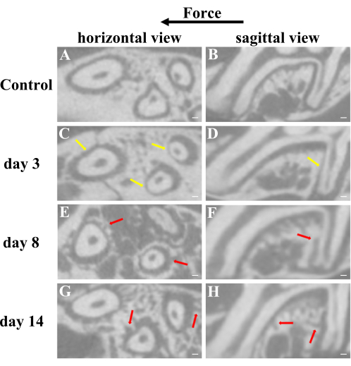
Figure 5: Representative micro-CT two-dimensional images from horizontal and sagittal views of different stages of M1 movement. (A,B) Under physiological circumstances, the low-density periodontal ligament is aequilatus and continuously occupies some space instead of being compressed and the surface of the alveolar bone is intact linear. (C,D) The periodontal ligament is broadening at the distal side and narrowing at the mesial side of roots, which can be observed on day 3 after surgery. (E–H) The lopsided periodontal ligament starts to revert and the surface of the alveolar bone becomes rough as a result of absorption and deposition of bone at days 8 and 14 after surgery. Yellow arrows refer to the compressed periodontal ligament. Red arrows refer to the rough surface of alveolar bone for the absorption and deposition of bone. * P < 0.05; *** P < 0.005. One-way ANOVA. Data are mean ± SD, n ≥ 3. Scale bar = 100 µm. Abbreviations: M1 = the maxillary first molar; M2 = the maxillary second molar; OTM = orthodontic tooth movement. Please click here to view a larger version of this figure.
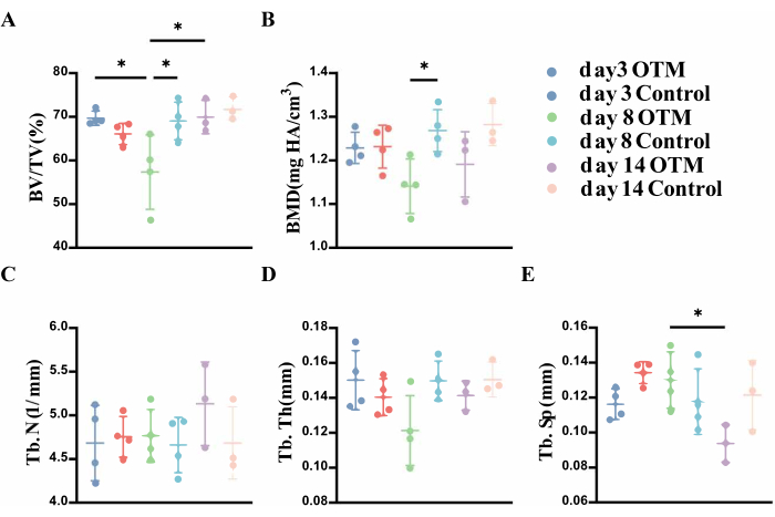
Figure 6: Statistical analysis of alveolar bone enclosed within the roots of M1 at different stages of M1 movement from micro-CT. (A) The significant decrease in the percent bone volume on day 8 indicates the active bone resorption between day 3 and day 8. The significant increase in the percent bone volume on day 14 indicates active bone formation between day 8 and day 14. (B) The significant difference on day 8 in the bone mineral density compared with the control side. also supports the above conclusion. (C–E) Three supplementary indicators were used for evaluation. Few significant differences were found, but the trend still supports the above conclusions. *P < 0.05. One-way ANOVA. Data are mean± SD, n ≥ 3. Abbreviations: M1 = the maxillary first molar; OTM = orthodontic tooth movement; BV/TV = percent bone volume; BMD = bone mineral density; Tb. N = trabecular number; Tb. Th = trabecular thickness; Tb. Sp = trabecular separation. Please click here to view a larger version of this figure.
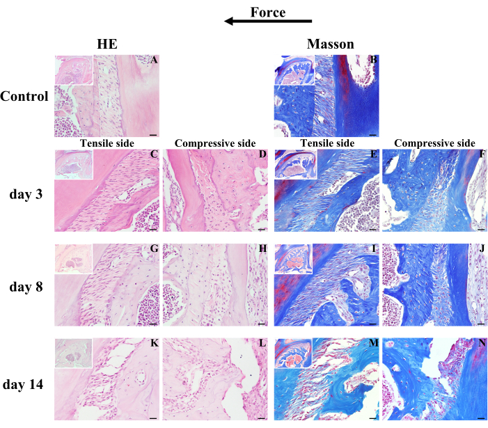
Figure 7: Representative results of hematoxylin-eosin staining and Masson-trichrome staining of the different stages of M1 movement. (A,B) Under physiological conditions, the periodontal ligament fibers are subjected to certain forces with a distinct wave-like shape like "~", and the surface of the alveolar bone is intact linear. When M1 is subjected to mechanical load, (C,E,G,I,K,M) fiber has been stretched tightly at the tension side, while (D,F,H,J,L,N) periodontal ligament fiber has been compressed with morphological ambiguity. (C–N) The surface of the alveolar bone becomes more and more uneven as bone modeling proceeds. Scale bar = 20 µm. Abbreviations: M1 = the maxillary first molar; OTM = orthodontic tooth movement. Please click here to view a larger version of this figure.
| Species | Moving tooth | Anchorage | Device | Moving direction | Reference |
| Murine | first molar | incisors | coil spring | mesial | 14,15 |
| first molar | second molar | elastic band | mesial | 16 | |
| Rat | first molar | mini implant | coil spring | mesial | 17 |
| first molar | incisors | coil spring | mesial | 18 | |
| second and third molar | contralateral homonymous teeth | spring expansion appliance | buccal | 19 | |
| first molar | second molar | orthodontic wire | mesial | 20 | |
| Rabbit | first premolar | incisors | coil spring | mesial | 21 |
| first premolar | mini implant | coil spring | mesial | 22 | |
| incisor | contralateral homonymous teeth | coil spring | distal | 23 | |
| incisor | contralateral homonymous teeth | Omega loop | distal | 24 | |
| Dog | second premolar and first molar | mini implant | coil spring | mesial | 25 |
| second premolar | canine | coil spring | mesial | 26 | |
| first premolar | mini implant | elastic band | distal | 27 | |
| lateral incisor | canine | elastic band | distal | 28 | |
| Pig | first molar | deciduous third molar and mini implant | coil spring | mesial | 29 |
| first molar | second molar | orthodontic wire | buccal | 30 | |
| Monkey | central incisor | first molar, premolar, canine and lateral incisor | coil spring and orthodontic wire | labial | 31 |
| Cat | canine | mini implant | coil spring | mesial | 32 |
Table 1: Summary of the existing animal orthodontic models. The table lists the commonly used models of conventional laboratory animals that focus on simple orthodontic tooth movement. They always consist of three elements: the target moving tooth, the anchorage, and the connecting device to add mechanical load. Various orthodontic programs have been derived by changing the three elements. Complex orthodontic tooth movements with multiple teeth have been excluded.
Supplementary Figure S1: Enlarged versions of the spring. (A) Without and (B) with mechanical load. Scale bar = 5 mm. Please click here to download this File.
Supplementary Figure S2: The method of clamping the ligature wire with forceps. During protocol step 2.4., the safest and most convenient way to clamp the bend of the ligature wire before piercing is shown here. Please click here to download this File.
Supplementary Figure S3: The scope of resin coating. During protocol step 2.9, the incisor end of the spring (A) without and (B) with a covering with resin is shown here. The resin must not be added to the elastic part. Please click here to download this File.
