High-density EEG Recordings of the Freely Moving Mice using Polyimide-based Microelectrode
Summary
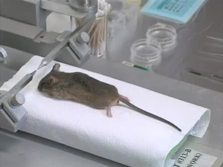
In this article, we described the surgery procedure and handling tips for implantation of ultra-thin polyimide-based microelectrode array (PBM-array) on the mouse skull for acquisition of high-density encephalography (EEG) in a mouse model.
Abstract
Electroencephalogram (EEG) indicates the averaged electrical activity of the neuronal populations on a large-scale level. It is widely utilized as a noninvasive brain monitoring tool in cognitive neuroscience as well as a diagnostic tool for epilepsy and sleep disorders in neurology. However, the underlying mechanism of EEG rhythm generation is still under the veil. Recently introduced polyimide-based microelectrode (PBM-array) for high resolution mouse EEG1 is one of the trials to answer the neurophysiological questions on EEG signals based on a rich genetic resource that the mouse model contains for the analysis of complex EEG generation process. This application of nanofabricated PBM-array to mouse skull is an efficient tool for collecting large-scale brain activity of transgenic mice and accommodates to identify the neural correlates to certain EEG rhythms in conjunction with behavior. However its ultra-thin thickness and bifurcated structure cause a trouble in handling and implantation of PBM-array. In the presented video, the preparation and surgery steps for the implantation of PBM-array on a mouse skull are described step by step. Handling and surgery tips to help researchers succeed in implantation are also provided.
Protocol
Discussion
Here we report surgical and recording procedures to acquire high-density EEG in freely moving mice. This method enables us to obtain functional brain maps from mouse model to study molecular mechanisms of spontaneous rhythmic1,2 or event related brain activities.
Acquisition of all the channels in the PBM-array is a necessary condition to obtain whole brain mapping, however making a secure contact for every channel is very challenging. To maintain consistent contact of the channel to the skull, the following procedures are found to be important. First of all, any tissue debris on the skull may set apart the electrode from the skull. Hence it is very important to remove all the tissue debris with sterilized cotton swabs and dry up the skull surface. Secondly, the ability of PBM-array which can stick to the skull surface is van der Waals force. It is suggested to apply a drop of tap water on the skull to build water layer before one apply PBM-array to the skull. Thirdly, the right viscosity of dental cement is very important. If it is too runny, it may build an insulating layer under the PBM-array. If it is too dense, the dental cement will easily fall apart from the skull due to its own weight. Lastly, at least three supporting microscrews should be implanted on the skull to make the dental cement tightly bound to the skull. The supporting microscrews hold up the dental cement and secure the headstage, which is essential for long-term study.
The application of PBM-array will be limited to chronic study with adult mice due to its size and weight. Based on our experience, mice heavier than 25 g are adequate to use. As further applications, through the null space between branches in our PBM-array, one may introduce secondary electrodes for recording or stimulation purpose.
Divulgations
The authors have nothing to disclose.
Acknowledgements
Supported by KIST Grant (2E21510), National Honor Scientist program of the Ministry of Education, and the Original Technology Research Program for Brain Science through the National Research Foundation of Korea funded by the Ministry of Education, Science and Technology (2010-0018944).
Materials
| Material Name | Type | Company | Catalogue Number | Comment |
|---|---|---|---|---|
| γ–butyrolactone | Sigma | H7629-500G |
References
- Choi, J. H., Koch, K. P., Poppendieck, W., Lee, M., Shin, H. S. High resolution Electroencephalography in Freely Moving Mice. J Neurophysiol. , .
- Lee, M., Shin, H. S., Choi, J. H. Simultaneous recording of brain activity and functional connectivity in the mouse brain. Conf Proc IEEE Eng Med Biol Soc. , 2934-2936 (2009).