Basic techniques and refinements of freeze-fracture processing of biological specimens and nanomaterials for examination by transmission electron microscopy are described. This technique is a preferred method for revealing ultrastructural features and specializations of biological membranes and for obtaining ultrastructural level dimensional and spatial data in materials sciences and nanotechnology products.
Freeze-fracture/freeze-etch describes a process whereby specimens, typically biological or nanomaterial in nature, are frozen, fractured, and replicated to generate a carbon/platinum “cast” intended for examination by transmission electron microscopy. Specimens are subjected to ultrarapid freezing rates, often in the presence of cryoprotective agents to limit ice crystal formation, with subsequent fracturing of the specimen at liquid nitrogen cooled temperatures under high vacuum. The resultant fractured surface is replicated and stabilized by evaporation of carbon and platinum from an angle that confers surface three-dimensional detail to the cast. This technique has proved particularly enlightening for the investigation of cell membranes and their specializations and has contributed considerably to the understanding of cellular form to related cell function. In this report, we survey the instrument requirements and technical protocol for performing freeze-fracture, the associated nomenclature and characteristics of fracture planes, variations on the conventional procedure, and criteria for interpretation of freeze-fracture images. This technique has been widely used for ultrastructural investigation in many areas of cell biology and holds promise as an emerging imaging technique for molecular, nanotechnology, and materials science studies.
The concept and practical application of freeze-fracture processing of biological specimens was introduced by Steere1 over half a century ago. The early apparatus appropriated disparate components into a working self-contained unit1. The original apparatus was modified and refined into commercially available instruments in order to accommodate the critical need for remote manipulation, maintenance of high vacuum, and the evaporation of carbon and metals to produce a replica suitable for examination by transmission electron microscopy (Figure 1 and Figure 2).
The typical instrument consists of a high vacuum chamber with specimen table and microtome arm having regulable liquid nitrogen throughputs (Figure 1). The chamber also houses two electron guns, one for stabilizing carbon evaporation positioned at a 90º angle to the specimen stage and the other for platinum/carbon shadowing at an adjustable angle, typically 15º – 45º (Figure 2). Power to the unit is applied to operate the vacuum pump and electronic panels regulate temperature adjustment and electron gun control.
Originally conceived as a means to achieve improved imaging of viruses, freeze-fracture gained even more popularity as a technique for the examination and analysis of cell membranes and their specializations2,3. Indeed, this procedure has been integral to elucidating structure/function relationships in cells and tissues and many of these studies stand as classic contributions to cell and molecular biology4-9. The major goal and rationale for the development of the freeze-fracture technique was to limit artifacts observable at electron microscopic resolution deriving from chemical fixation and processing used in conventional biological electron microscopy. Here the goal is to limit chemical fixation and to freeze the specimen with sufficient speed and frequently in the presence of a cryoprotectant in order to limit ice crystal formation and other freezing artifacts. More recently, this technique has found a resurgence of interest from molecular biologists and materials science investigators for examination of nanoparticles and nanomaterials.
Freeze-fracture and freeze-etch images exhibit a three-dimensional character and sometimes are mistaken for scanning electron micrographs. However, freeze-fracture preparations are examined by transmission electron microscopy and their major contribution to high resolution morphologic studies is their unique representation of structure/function elements of cell membranes. Freeze-fracture processing is initiated by freezing cells and tissues with sufficient speed to limit ice crystallization and/or with the use of cryoprotectant agents such as glycerol. The specimens are then fractured under vacuum and a replica is generated by evaporation of carbon and platinum over the fractured surface. The original specimen is digested from the replica which is retrieved onto a standard EM specimen grid. Another common misinterpretation of freeze-fracture images is that they depict cell surfaces. However the basic premise of freeze-fracture is that biological membranes are split through the lipid bilayer by the fracture process (Figure 3). This process in biological membranes yields two fracture faces, one which reveals the organization of the half of the membrane adjacent to the cytoplasm, the PF-face, and one which reveals the half of the bimolecular leaflet of the membrane that is adjacent to the extracellular milieu, the EF-face. True cell surfaces are not represented in freeze-fracture images but only appear when the subsequent added step of freeze-etching following the fracture procedure is used. In order to effectively etch previously fractured specimens to reveal surface detail, specimens must be frozen at a rapid rate and without unetchablecryoprotectant. Etching of water from the surface of the fractured specimen revealing underlying features is accomplished by positioning the cooling microtome arm over the specimen stage creating a temperature differential between the stage holding the specimen and the cooling microtome arm which causes water to sublime from the surface. When water is sublimed from the surface of the fractured specimen during the freeze-etching maneuver, then aspects of actual cell surfaces, extracellular matrix, cytoskeletal structures, and molecular assemblies may be revealed at high resolution. Thus freeze-fracture and freeze-etch are not interchangeable terms but rather reflect a step-wise process the latter of which may not be necessary or desirable depending on the needs of the particular study.
Following the freeze-fracture/freeze-etch procedures, the fractured surfaces are subjected to directed evaporative coats of carbon and platinum in order to provide support and imaging contrast to the replica. The platinum/carbon imaging evaporation may be unidirectional or rotary and is accomplished by either resistance or electron guns. Unidirectional shadowing from a known angle, typically 30º – 45º, is useful in performing certain morphometric calculations. Specimens that have been subjected to deep-etching typically are rotary shadowed and the resultant images of these specimens are photographically reversed for evaluation.
The historical as well as a present goal of the freeze-fracture/freeze-etch technique is to limit chemical fixation and processing specimen artifacts that are associated with more conventional transmission electron microscopy procedures. However, this technique provides a substantive advantage in its ability to confer three-dimensional detail and thus facilitate acquisition of morphometric data in biological, material science, and nanotechnology specimens. Freeze-fracture and freeze-etch procedures are complex and multi-faceted and some aspects of its application are customized. This presentation offers a survey view of the major features of the process and the reader is referred to comprehensive published protocols10,11 in order to address the details and customize the process for specific research needs.
1. Preparation of Biological Specimens for Freeze-fracture/Freeze-etch
2. Freezing and Storage of Specimens In Advance of Freeze-fracture
3. Operation of the Freeze-fracture Instrument and Specimen Processing
4. Ultrastructural Examination of Freeze-fracture/etch Replicas
The key premise of freeze-fracture image interpretation is that fracture planes pass through the lipid bilayer of membranes conferring two fracture faces, called by convention the PF-face (plasma fracture-face) and EF-face (extracellular fracture-face) (Figure 3). The PF-face is the half of the membrane lipid bilayer adjacent to the cytoplasm of the cell and the EF-face is the half of the membrane lipid bilayer adjacent to the extracellular milieu. The freeze-fracture technique is particularly useful for the investigation of membrane structure and the two faces are typically distinctively different with PF-faces being populated with many membrane associated particles in contrast to EF-faces which contain fewer. The cytoplasmic contents of freeze-fractured cells are typically coarse in appearance and are not particularly revealing although membrane bound organelles such as nuclei and Golgi can be readily identified. Of particular interest to investigators using this technique are specializations of membrane structure that can be interpreted for their function. These include specific distributions of membrane associated particles, ciliary membrane specializations, and intercellular junctions.
Cilia-associated Structures
Residing in the cell membrane at the base of each eukaryotic cilium and flagellum is an array of membrane associated particles organized into strands encircling the shaft of the cilium and known as the ciliary necklace (Figure 8)12-16. This structure exhibits some degree of morphologic heterogeneity in various species and it has been speculated to be multifunctional inasmuch as it appears prior to the emergence of the ciliary shaft during ciliogenesis and remains in place in the mature cilium. The nascent ciliary necklace derives from the aggregation and organization of membrane particle arrays prior to the time of the emergence of the ciliary shaft during ciliogenesis suggesting its possible participation in early organization of the developing axoneme14.
Tight Junctions and Epithelial Permeability
In various epithelia, freeze-fracture studies reveal a sophisticated organization of anastomosing strand and groove structures encircling the apical aspect of the basolateral borders. This belt-like structure is known as the tight junction or zonulaoccludens (Figure 9) and is believed to act as a regulator of epithelial permeability to the paracellular flux3, 17-20. Tight junctions with few strands have been described as “leaky” while those with more complex organization are described as “tight”. This organization appears to fit the function of the epithelia to which they are associated. The PF-faces of tight junctions appear as strands while the EF-faces exhibit complementary grooves.
Gap Junctions and Intercellular Communication
Gap junctions (Figure 10) appear in freeze-fracture preparations of a variety of tissues and are represented by dense arrays of particles on PF-faces and complementary pits on EF-faces. These structures are thought to represent membrane sites that facilitate intercellular communication. In tissues where they are present, demonstrations of the passage of low molecular weight fluorescent dyes and calcium fluxes have been demonstrated21-24 suggesting that they represent a physical route for the passage of signaling molecules.
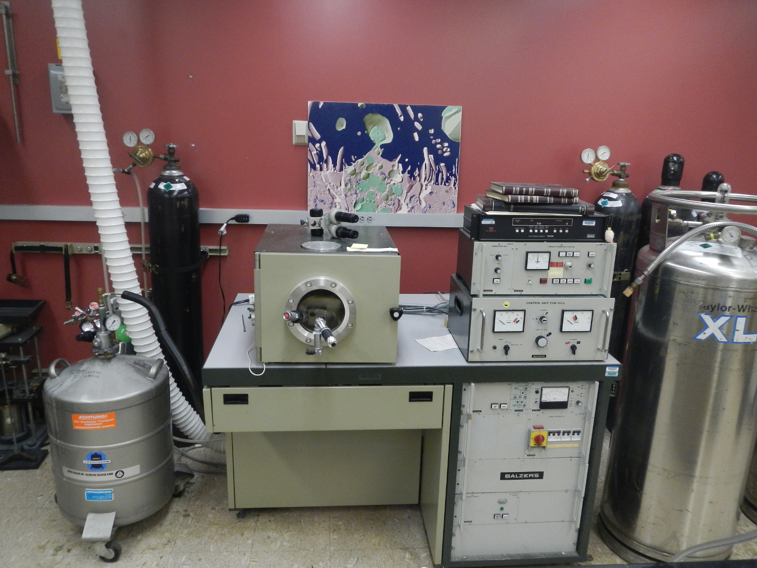
Figure 1. Layout of a commercial freeze-fracture/etch plant. At far left is a pressurized Dewar feeding cooling liquid nitrogen to the specimen stage and cooling microtome arm under controlled conditions. At center is the unit with specimen chamber and electronic control panels to the right. At right is an additional liquid nitrogen tank on which the vent gas is used to bring the specimen chamber to atmosphere.
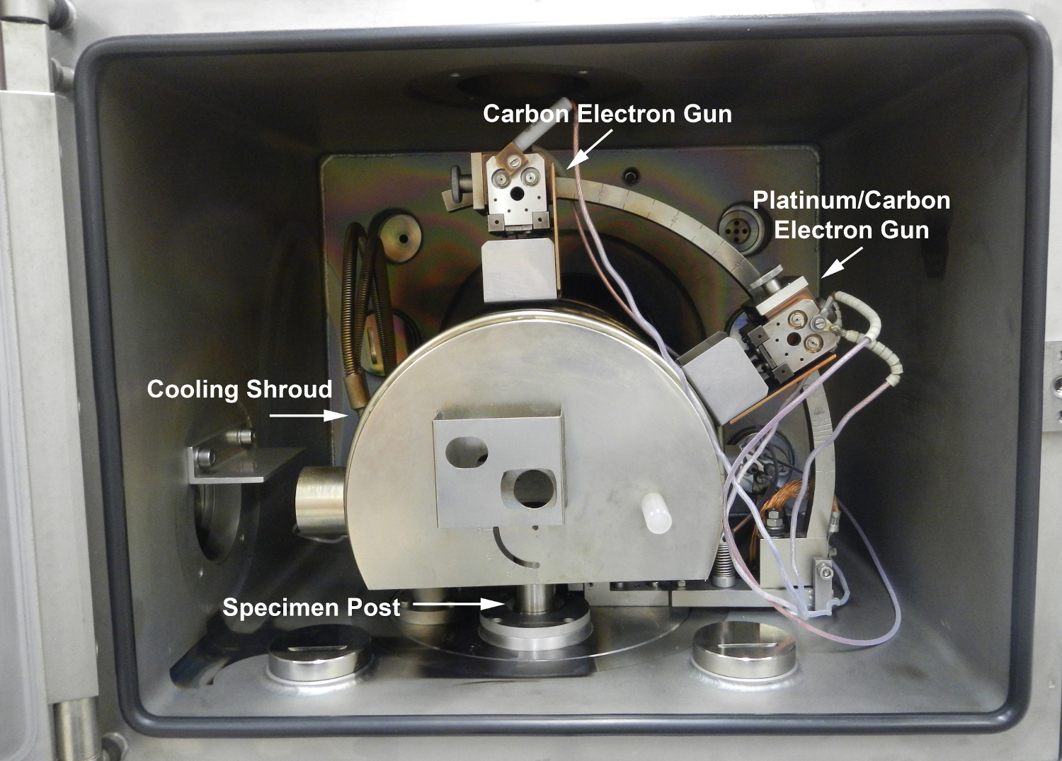
Figure 2. Freeze-fracture/etch plant specimen chamber with door opened to reveal positions of directionally aimed electron guns, cooling shroud, and specimen post where specimens in brass holders are positioned. Specimens are introduced to the chamber through a port to the left of the chamber.
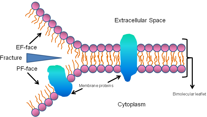
Figure 3. Diagrammatic representation of the principle of freeze-fracture. The fracture faces derive from the splitting of the membrane through the lipid bilayer producing an extracellular face (EF-face) and a face that is proximal to the cytoplasmic aspect, the PF-face. True unfractured membrane surfaces are seen only by etching subsequent to the freeze-fracture maneuver.
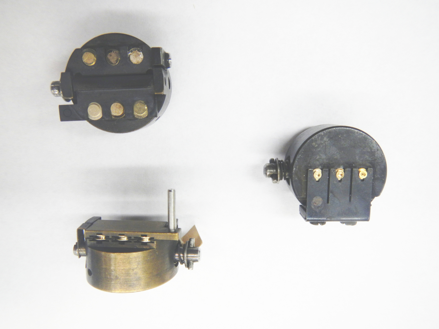
Figure 4. Two types of specimen mounts for freeze-fracture/etch procedures. (Left) A double replica specimen holder booklet is used for conventional freeze-fracture procedures performed without etching. The specimen is sandwiched between two gold specimen stubs and positioned in the brass booklet. The specimen is fractured by opening the booklet under vacuum in the specimen chamber (See freeze-fracture_movie1.mov). (Right) A mount used primarily for freeze-etching. The specimen is positioned on the gold stubs and locked into the brass holder. The specimen is fractured by gentle shaving with a razor blade fixed in the microtome arm. This configuration is preferred for etching procedures (See freeze-etch_movie2.mov).
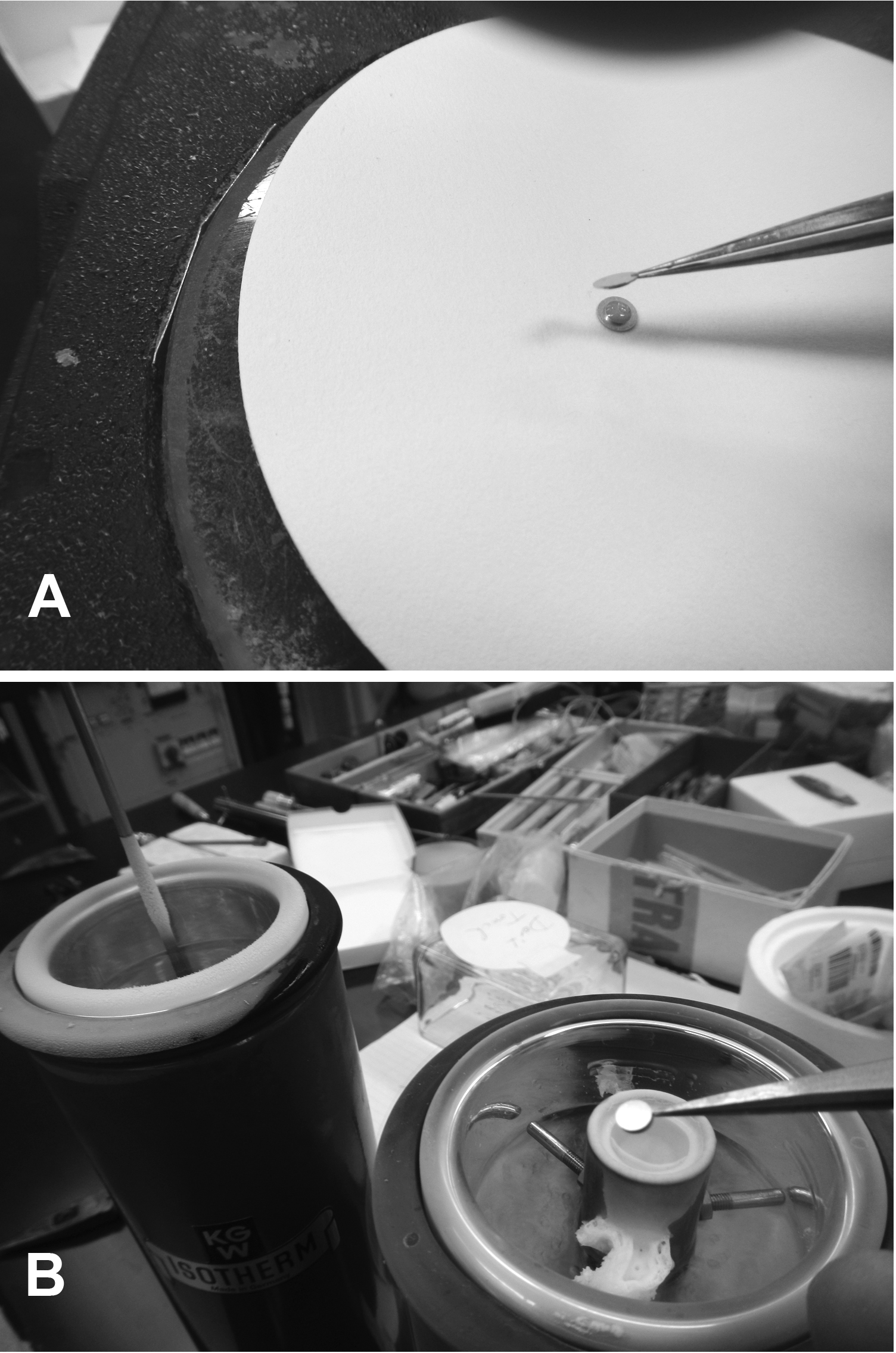
Figure 5. Preparation of a freeze-fracture specimen mount. The specimen is sandwiched between two gold mounts (A) and frozen in a well containing liquid nitrogen cooled propane (foreground) with subsequent transfer to a holding Dewar containing liquid nitrogen (background) (B).
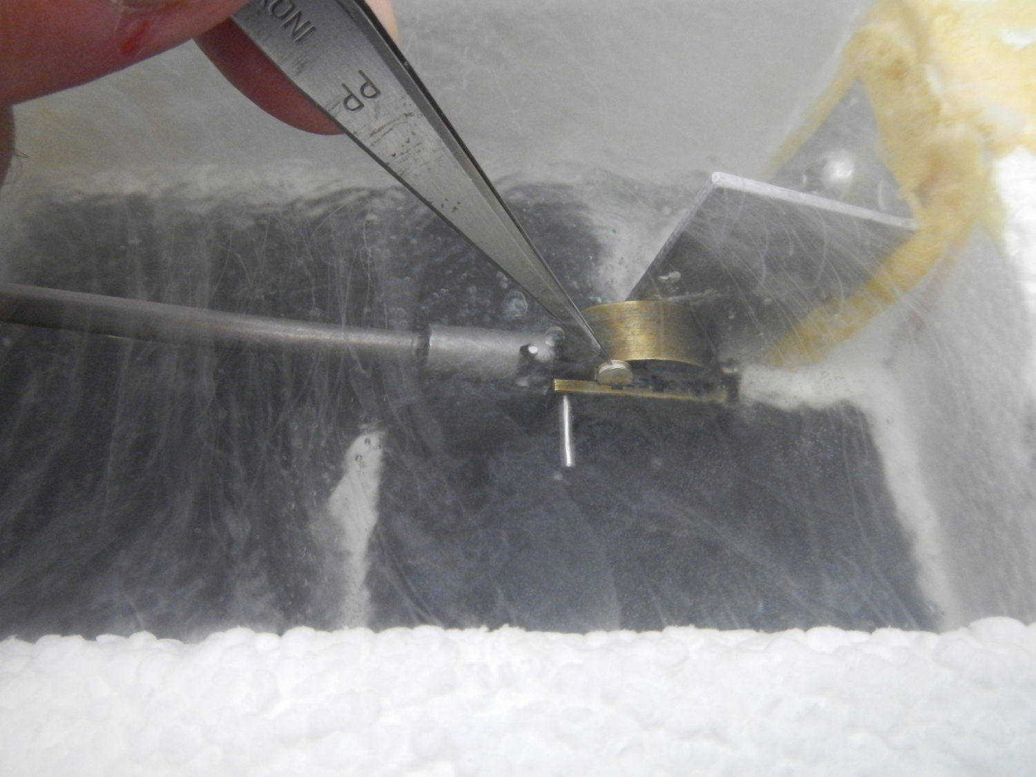
Figure 6. Demonstration of positioning of a frozen freeze-fracture specimen into the double replica specimen holder booklet in preparation for introduction to the specimen chamber of the freeze-fracture/etch plant.
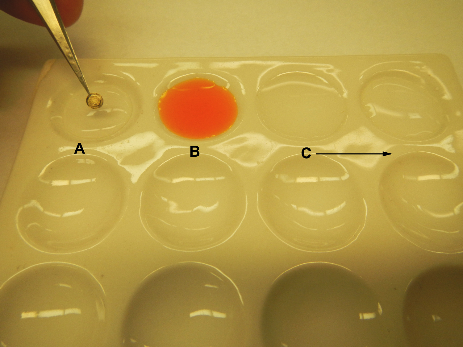
Figure 7. Retrieval of replicas following fracture and shadowing in the freeze-fracture/etch plant. “A” is a clean water surface in a spot plate. The replica floated from the specimen stub is transferred to “B” a well containing an acidified solution of sodium dichromate or full strength household bleach for digestion of the tissue from the replica. “C” represents subsequent clean water surfaces to which the cleaned replica is transferred prior to being retrieved onto a copper electron microscopy grid.
Figure 8. Cilia related structures revealed by freeze-fracture. White arrows point to specialized membrane particle arrays on the luminal border of epithelial cells undergoing ciliogenesis. These particle arrays represent nascent ciliary necklaces which reside at the bases of emergent and mature cilia (black arrow). Please click here to view a larger version of this figure.
Figure 9. Fracture through epithelial cell membranes revealing examples of PF- and EF-fracture faces. The strand and groove organization of tight junctional complexes is evident and the intercellular space is marked by arrows. Please click here to view a larger version of this figure.
Figure 10. A freeze-fracture image of a gap junction in rat liver. Particles are evident on the PF-face and complementary pits are evident on the EF-face. Please click here to view a larger version of this figure.
Figure 11. Immunohistochemical localization of a connexin using a colloidal gold labeled antibody on a freeze-fracture preparation illustrating specific localization on the gap junction. Please click here to view a larger version of this figure.
Figure 12. An example of rapid freezing with deep etching and rotary shadowing. The epithelial cell has been fractured through the cytoplasm and a PF-face is evident (arrowheads). Behind the arrowheads can be seen a true cell surface revealed by subsequent etching. Please click here to view a larger version of this figure.
Figure 13. An example of rapid freezing with deep etching and rotary shadowing to reveal molecular complexes comprising a bovine tracheal ciliaryaxoneme. Please click here to view a larger version of this figure.
In the years following its introduction and commercial availability, freeze-fracture/etch procedures were widely utilized for investigations of biological membrane structure. Indeed, the best perspectives of some of the structural specializations of membranes have been obtained in freeze-fracture/etch preparations. These studies not only contributed to understanding of the structural organization of membranes but also provided insights into how structure and function are related.
The advent of routine biological electron microscopy brought about an awareness that chemical treatments with the aldehyde fixatives, reactive chemicals, and heavy metals required to confer differential electron density to biological specimens themselves contributed to the generation of artifact. The development of freeze-fracture technology was based in part on an effort to reduce processing artifact. Nevertheless, it has been recognized that freeze-fracture/etch introduces its own set of artifacts, a major one of which is ice crystal damage. Tissues plunged directly into liquid nitrogen experience a reduced cooling rate due to the formation of an insulating layer of nitrogen gas surrounding the specimen which results in the formation of ice crystals that obliterate ultrastructural detail. This problem is overcome with the use of cryoprotectants such as glycerol and by freezing the tissue first in liquid nitrogen-cooled propane. Historically, plunge freezing was performed in liquid nitrogen cooled chlorofluorocarbons but these materials have been phased out of use due to their adverse effects on the environment. Even in the best cryoprotective conditions, the nature of the process inevitably results in a coarse, gravel like surface in cytoplasmic fractures; however, fractures through membrane structures reveal well organized features having specific planar organizations relative to their orientation in the cell membrane. These images are possible only with the use of cryoprotectant agents such as glycerol that limit ice crystal damage, and glycerol itself in some cases also may introduce artifactual redistribution of membrane associated particles. Moreover, glycerol cannot be sublimated from the fractured surface thus limiting the opportunity for successful etching. If the subsequent etching procedure is desirable, then the specimen must be either rapidly frozen in a fashion that limits ice crystal damage using either liquid helium or nitrogen slush and/or approached by the use of a cryoprotectant such as acetone which is readily sublimated from fractured surfaces.
Although Steer’s initial report was focused on imaging viruses, it is in membrane structure that freeze-fracture/etch found more extensive application. Indeed, structures such as tight and gap junctions and ciliary membrane specializations have been elegantly revealed in freeze-fracture preparations. Freeze-fracture has found considerable utility in achieving an understanding of membrane differentiation during development15,17,24 and in membrane pathology25-30. Previous reports from this laboratory, have demonstrated the pattern of differentiation of tight junctional complexes during airway development, disruption of ciliary membrane structures associated with experimental infectious agent exposure, and degradation of tight junctional complexes in airway epithelial cells associated with air pollutant and tobacco smoke exposure in experimental animals and human subjects.
Technical Extensions of the Freeze-Fracture/Freeze-etch Procedure
The quenching method using liquefied propane to freeze specimens described here is perhaps the most common approach to freezing biological specimens for conventional freeze-fracture. However, other approaches to freezing must be appropriated where freeze-etching is to be performed. Since glycerol is a non-etchablecryoprotectant, specimens for freeze-etching must be frozen in ways that limit ice crystal formation. This may be accomplished by using an etchablecryoprotectant such as acetone and/or by freezing the specimen mount against a metal surface cooled with liquid helium or liquid nitrogen slush. Rapid freezing without cryoprotectants also may be accomplished using spray freezing or high pressure freezing in liquefied propane.
Recent efforts to further relate structure and function using freeze-fracture technology have appropriated this technique in concert with immunohistochemical labeling31,32. Here, antibodies to specific antigens can be effectively and accurately localized to membrane sites (Figure 11).
While freeze-fracture with unidirectional shadowing is by far the most widely used protocol, some experimental designs will call for rapid freezing with little or limited cryoprotection, accompanied by etching of the fractured surface to reveal true cell surfaces, extracellular matrix, and/or macromolecular complexes, and rotary shadowing to impart contrast16 (Figure 12 and Figure 13).
There is a growing interest in applications of freeze-fracture in nanotechnology, materials science, and in using this technique as an imaging tool in molecular biology. Indeed, nanomaterials in many ways may be consistent in their organization with viral structures for which freeze-fracture was originally envisioned as a means for imaging. Moreover, manufactured liposomes, structures similar in form to biological membranes, are being widely studied for targeted delivery of pharmaceutical agents and directed gene therapy. Because their organization is essentially membrane like, freeze-fracture processing may have considerable utility in producing revealing images as a component in developing these therapies33.
In summary, freeze-fracture technologies have been of historic importance in characterizing the organization and function of cell membranes. However, freeze-fracture is finding new areas of utility in coordination with molecular biology and nanotechnology and almost certainly will contribute to advances in these rapidly emerging fields.
The authors have nothing to disclose.
This presentation was supported by a Clinical Innovator Award to JLC from the Flight Attendant Medical Research Institute and by the United States Environmental Protection Agency. Although the research described in this article has been funded wholly or in part by the United States Environmental Protection Agency through Cooperative Agreement CR83346301 with the Center for Environmental Medicine, Asthma, and Lung Biology at The University of North Carolina at Chapel Hill, it has not been subjected to the Agency’s required peer and policy review, and therefore does not necessarily reflect the views of the Agency and no official endorsement should be inferred. Mention of trade names or commercial products does not constitute endorsement or recommendation for use.
Name of Material/ Equipment | Company | Catalog Number | Comments/Description |
Balzers Freeze-fracture/freeze-etch plant | Balzers | BAF400T | |
Standard buffers | various suppliers | ||
standard aldehyde fixatives | various suppliers | ||
sodium dichromate | various suppliers | ||
sulfuric acid | various suppliers | ||
Disposable supplies for Platinum/Carbon Evaporation | Technotrade International | ||
Liquid nitrogen | various suppliers | ||
Freon | various suppliers | ||
Disposable supplies for electron microscopy | Electron Microscopy Sciences | ||
Transmission electron microscope | Carl Zeiss Inc. |