Summary

低圧走査型電子顕微鏡を用いたカーボンナノチューブの森の精密フライス

Published: February 05, 2017
doi:

Summary

Low pressure scanning electron microscopy in a water vapor ambient is used to machine nanoscale to microscale features in carbon nanotube forests.

Abstract

A nanoscale fabrication technique appropriate for milling carbon nanotube (CNT) forests is described. The technique utilizes an environmental scanning electron microscope (ESEM) operating with a low pressure water vapor ambient. In this technique, a portion of the electron beam interacts with the water vapor in the vicinity of the CNT sample, dissociating the water molecules into hydroxyl radicals and other species by radiolysis. The remainder of the electron beam interacts with the CNT forest sample, making it susceptible to oxidation from the chemical products of radiolysis. This technique may be used to trim a selected region of an individual CNT, or it may be used to remove hundreds of cubic microns of material by adjusting ESEM parameters. The machining resolution is similar to the imaging resolution of the ESEM itself. The technique produces only small quantities of carbon residue along the boundaries of the cutting zone, with minimal effect on the native structural morphology of the CNT forest.

Introduction

カーボンナノチューブ(CNT)とグラフェンは、その優れた強度、耐久性、熱的、および電気的特性の大きな注目を集めている炭素系ナノ材料です。カーボンナノ材料の精密加工は、研究の新興話題となり、エンジニアリングおよびエンジニアリングのさまざまなアプリケーションに向けて、これらの材料を操作する可能性を提供しています。加工カーボンナノチューブとグラフェンは、最初に関心のナノスケールの領域を特定するために、次に選択関心領域内の材料のみを除去するために、ナノスケールの空間精度を必要とします。例としては、(また、CNTアレイとして知られている)、垂直に配向CNTフォレストの加工を考慮してください。 CNTフォレストの断面を正確触媒膜のリソグラフィパターニングによって定義することができます。垂直に配向された森林の上面は、しかし、頻繁に乏しい不均一な高さと一緒に注文されています。このような熱界面材料などの表面に敏感なアプリケーションの場合、トン彼は、不規則な表面は、最適な表面接触を妨害し、デバイス性能を低下させることができます。均一な平坦な表面を作成するために、不規則な表面の精密トリミングは、潜在的に利用可能な接触面積を最大化することにより、より良い、より再現性能を提供することができます。

ナノ材料のための精密機械加工技術は、しばしば、このような硬化工具による穴あけ、フライス加工、研磨などの従来のマクロスケール機械加工技術を似ていません。現在までに、精力的なビームを用いた技術は、カーボンナノ材料の部位選択フライスで最も成功しています。これらの技術は、レーザー、電子ビーム、イオンビーム(FIB)照射を集束を含みます。これらのうち、レーザ加工技術は、最も迅速な材料除去速度1、2提供します 。しかしながら、レーザシステムのスポットサイズは、多くのミクロンのオーダーであり、そのような単一の炭素nはナノメートルスケールのエンティティを分離するには大きすぎます人口密度の高い森林内anotubeセグメント。対照的に、電子及びイオンビーム・システムは、数ナノメートルまたは直径が小さいスポットに集束することができるビームを生成します。

FIBシステムは、特にナノスケールの粉砕および材料の堆積のために設計されています。これらのシステムは、選択された領域から材料をスパッタするガス状金属イオンのエネルギービーム(典型的にはガリウム)を利用します。 CNTのFIBミリングは達成可能であるが、しばしば森3、4の周辺地域におけるガリウムおよび炭素再堆積などの意図しない副生成物です。技術はCNTフォレストのネイティブ外観と動作を変更、再堆積材料マスク、CNTフォレストのために使用され、および/または選択されたミリング領域の形態を変化させるされている場合。ガリウムは、電子ドーピングを提供し、CNT内に埋め込むことができます。このような結果は、多くの場合、CNTフォレストのための法外FIBベースのフライス加工を行います。

<p class=「jove_content ">透過型電子顕微鏡(TEMを)材料の内部構造を調べるために、電子の微細に集束ビームを利用します。 TEM動作のための加速電圧は、通常、80〜300 kVの範囲です。 CNTのノックオンエネルギーが86.4 keVの5であるため、TEMによって生成される電子のエネルギーは、直接CNT格子から原子を除去し、高度に局在化フライス加工を誘導するのに十分です。潜在的に、サブナノメートルの精度5、6、7との技術工場のカーボンナノチューブ;しかし、このプロセスは非常に遅いです – しばしばミル単一CNTに分を必要とします。重要なことには、TEMベースのミリングの手法は、最初成長基板から除去され、処理のためにTEMグリッド上に分散されるCNTを必要とします。その結果、TEMベースの方法は、一般的にCNTをリジッド基板上に残っている必要があるCNTフォレストミリングと互換性がありません。

CNのフライス走査型電子顕微鏡(SEMの)によるT林も注目されています。技術ベースのTEMとは対照的に、SEMの機器は、典型的には、直接の炭素原子を除去するために必要なノックにエネルギーを付与するのに十分なエネルギーを有する電子を加速することができません。むしろ、SEMベースの技術は、低圧力のガス状酸化剤の存在下で電子ビームを利用します。電子ビームを選択的損傷CNT格子や、H 2 O 2及びヒドロキシルラジカルなどのより反応性の種に気体雰囲気を分離することができます。水蒸気と酸素が選択領域のエッチングを達成するための最も一般的に報告ガスです。 SEMベースの技術は、多段階の化学的プロセスに依存しているため、多数の処理変数は、プロセスの微粉砕速度および精度に影響を与え得ます。以前に予想されるように、加速電圧とビーム電流の増加が直接ため増加したエネルギー束のミリングレートを増加させることが観察されています"外部参照"> 11。チャンバ圧力の効果はそれほど明らかです。低すぎる圧力は、ミリング速度を減少させる、酸化剤の不足に苦しんでいます。さらに、オーバー豊富ガス種の電子ビームを散乱し、粉砕領域に電子束を減少し、また、材料除去速度を減少させます。

ラシターによって使用されるものと同様のカーボン除去率、アプローチを推定し、電子は基板表面をエッチングする反応種を生成するために表面の近くに前駆体分子と相互作用することにより12が 、使用されたラックに。このモデルから、エッチング速度は次のように推定されます

方程式

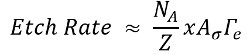
N Aは、エッチャント種の表面濃度であり、Zは、利用可能な反応部位の表面濃度であり、xは揮発性のエッチングに関する化学量論係数であります生成物は反応体に対して生成され、σは、電子水蒸気衝突から所望のエッチング種を生成する確率を表し、γE表面に電子束です。 Zは、ほぼ一定であり、NAよりも有意に大きいことが想定され、一方、xおよびσの因子は、1とみなされます。更なる詳細は、我々の以前の研究で発見することができます。 11

この記事では、手順が個々のCNT大量に(立方数十マイクロメートル)材料除去に至るまでミル領域にSEM内の低圧水蒸気を使用する探求されています。ここでは、小面積の長方形、水平ラインスキャン、電子ビームのソフトウェア制御ラスタリングを使用することによってESEMを使用して、ミルCNTフォレストに使用される技術を実証します。物質一覧で概説されるように追加のソフトウェアおよびハードウェアは、パターン生成のために必要とされます。重点は、相対的な除去に配置されていますLY大(立方ミクロンの100年代)CNTフォレストの材料体積なので、以下の処理条件が比較的積極的です。

サンプルおよびサンプルのスタブを取り扱う際には、使い捨てニトリル手袋を着用することが重要です。これは、スタブまたはサンプルに移し、その結果、ポンプの有効性を悪化さから油を防ぐことができます。

Protocol

フライス用CNTフォレストサンプルの調製 CNTの合成 原子層堆積13または他の物理蒸着法を用いて、熱酸化シリコンウエハー上に酸化アルミニウム(アルミナ)を10nmを堆積させます。 堆積物14または他の物理的蒸着法、スパッタによりアルミナ支持体層上に鉄の1ナノメートル。 このような熱化学蒸着15</sup…

Representative Results

ESEM技術はCNT森林熱CVD 15,16を使用して合成ミルに使用されました。森の中からいくつかのCNTの選択した領域の除去は、 図2〜11に示されています。このデモでは、パラメータが5 kVで、3のスポットサイズ、11 Paで、170,000X倍率が含まれ、2ミリ秒の滞留時間、および30μmの開口部。 <p class="jove_cont…

Discussion

比較的大きな(ミクロンスケール)を粉砕するためのプロトコルの詳細ベスト・プラクティスは、CNTの森林でいます。一般的に、材料除去速度は、加速電圧、スポットサイズ、及びアパーチャ径を小さくすることによって低減することができます。森林内の特定のCNTをトリミングするには、推奨条件は5 kVで、3のスポットサイズ、直径が50μm以下である開口部を含みます。電子ビームは囲まれ…

Disclosures

The authors have nothing to disclose.

Acknowledgements

This work was supported by the Air Force Office of Scientific Research grant FA9550-16-1-0011 and University of Missouri startup funds. The authors would like to thank the University of Missouri Electron Microscopy Core facility for assistance with SEM imaging and use of patterning equipment and software.

Materials

100 mm diameter silicon wafer with 1 micron thermal oxide University Wafer Beginning substrate
Iron sputter target Kurt J. Lesker EJTFEXX351A2 Sputter target 
Savannah 200 Cambridge For atomic layer deposition of alumina
Quanta 600F Environmental SEM FEI Environmental scanning electron microscope used to support a low-pressure water vapor ambient environment for CNT forest milling
xT Microscope Control software FEI 4.1.7 Control software used on Quanta 600F ESEM
Nanometer Pattern Generation System – Software JC Nabity Lithography Systems Version 9 Software used for electron-beam lithography
Dedicated computer with PCI516 Lithography board Equipment used for electron-beam lithography
DesignCAD software V 21.2 Optional equipment used to generate patterns for electron-beam lithography
E-beam lithography mount Ted Pella 16405 Electron beam lithography mount with a Faraday cup and gold nanoparticles on carbon tape
Picoammeter Keithley 6485 Used with the Faraday cup to quantify beam current
12.7 mm diameter SEM stub Ted Pella 16111 SEM stub
45 degree pin stub holder Ted Pella 15329 Optional equipment used to mill the cross section of a CNT forest

References

  1. Labunov, V., et al. Femtosecond laser modification of an array of vertically aligned carbon nanotubes intercalated with Fe phase nanoparticles. Nanoscale Res Lett. 8 (1), 375-375 (2013).
  2. Lim, K. Y., et al. Laser Pruning of Carbon Nanotubes as a Route to Static and Movable Structures. Adv Mater. 15 (4), 300-303 (2003).
  3. Raghuveer, M. S., et al. Nanomachining carbon nanotubes with ion beams. Appl Phys Lett. 84 (22), 4484-4486 (2004).
  4. Sears, K., Skourtis, C., Atkinson, K., Finn, N., Humphries, W. Focused ion beam milling of carbon nanotube yarns to study the relationship between structure and strength. Carbon. 48 (15), 4450-4456 (2010).
  5. Smith, B. W., Luzzi, D. E. Electron irradiation effects in single wall carbon nanotubes. J Appl Phys. 90 (7), 3509-3515 (2001).
  6. Banhart, F., Li, J., Terrones, M. Cutting Single-Walled Carbon Nanotubes with an Electron Beam: Evidence for Atom Migration Inside Nanotubes. Small. 1 (10), 953-956 (2005).
  7. Krasheninnikov, A. V., Banhart, F., Li, J. X., Foster, A. S., Nieminen, R. M. Stability of carbon nanotubes under electron irradiation: Role of tube diameter and chirality. Phys Rev B. 72 (12), 125428 (2005).
  8. Royall, C. P., Thiel, B. L., Donald, A. M. Radiation damage of water in environmental scanning electron microscopy. J Microsc. 204 (3), 185-195 (2001).
  9. Yuzvinsky, T. D., Fennimore, A. M., Mickelson, W., Esquivias, C., Zettl, A. Precision cutting of nanotubes with a low-energy electron beam. Appl Phys Lett. 86 (5), 053109 (2005).
  10. Liu, P., Arai, F., Fukuda, T. Cutting of carbon nanotubes assisted with oxygen gas inside a scanning electron microscope. Appl Phys Lett. 89 (11), (2006).
  11. Rajabifar, B., et al. Three-dimensional machining of carbon nanotube forests using water-assisted scanning electron microscope processing. Appl Phys Lett. 107 (14), 143102 (2015).
  12. Lassiter, M. G., Rack, P. D. Nanoscale electron beam induced etching: a continuum model that correlates the etch profile to the experimental parameters. Nanotechnology. 19 (45), 455306 (2008).
  13. Amama, P. B., et al. Influence of Alumina Type on the Evolution and Activity of Alumina-Supported Fe Catalysts in Single-Walled Carbon Nanotube Carpet Growth. ACS Nano. 4 (2), 895-904 (2010).
  14. Almkhelfe, H., Carpena-Nunez, J., Back, T. C., Amama, P. B. Gaseous product mixture from Fischer-Tropsch synthesis as an efficient carbon feedstock for low temperature CVD growth of carbon nanotube carpets. Nanoscale. , (2016).
  15. Maschmann, M. R., Ehlert, G. J., Tawfick, S., Hart, A. J., Baur, J. W. Continuum analysis of carbon nanotube array buckling enabled by anisotropic elastic measurements and modeling. Carbon. 66, 377-386 (2014).
  16. Maschmann, M. R., et al. Visualizing Strain Evolution and Coordinated Buckling within CNT Arrays by In Situ Digital Image Correlation. Adv Funct Mater. 22 (22), 4686-4695 (2012).
  17. Abadi, P. P. S. S., Maschmann, M. R., Baur, J. W., Graham, S., Cola, B. A. Deformation response of conformally coated carbon nanotube forests. Nanotechnology. 24 (47), 475707 (2013).
  18. Brieland-Shoultz, A., et al. Scaling the Stiffness, Strength, and Toughness of Ceramic-Coated Nanotube Foams into the Structural Regime. Adv Funct Mater. 24 (36), 5728-5735 (2014).
  19. Maschmann, M. R., Dickinson, B., Ehlert, G. J., Baur, J. W. Force sensitive carbon nanotube arrays for biologically inspired airflow sensing. Smart Mater Struct. 21 (9), 094024 (2012).
  20. Maschmann, M. R., et al. In situ SEM Observation of Column-like and Foam-like CNT Array Nanoindentation. ACS Appl Mater Inter. 3 (3), 648-653 (2011).
  21. Pathak, S., Raney, J. R., Daraio, C. Effect of morphology on the strain recovery of vertically aligned carbon nanotube arrays: An in situ study. Carbon. 63, 303-316 (2013).
  22. Pour Shahid Saeed Abadi, P., Hutchens, S. B., Greer, J. R., Cola, B. A., Graham, S. Effects of morphology on the micro-compression response of carbon nanotube forests. Nanoscale. 4 (11), 3373-3380 (2012).
  23. Maschmann, M. R. Integrated simulation of active carbon nanotube forest growth and mechanical compression. Carbon. 86, 26-37 (2015).
check_url/55149?article_type=t

Play Video

Cite This Article
Brown, J., Davis, B. F., Maschmann, M. R. Precision Milling of Carbon Nanotube Forests Using Low Pressure Scanning Electron Microscopy. J. Vis. Exp. (120), e55149, doi:10.3791/55149 (2017).

View Video