Summary

저압 주사 전자 현미경을 사용하여 탄소 나노 튜브 숲의 정밀 밀링

Published: February 05, 2017
doi:

Summary

Low pressure scanning electron microscopy in a water vapor ambient is used to machine nanoscale to microscale features in carbon nanotube forests.

Abstract

A nanoscale fabrication technique appropriate for milling carbon nanotube (CNT) forests is described. The technique utilizes an environmental scanning electron microscope (ESEM) operating with a low pressure water vapor ambient. In this technique, a portion of the electron beam interacts with the water vapor in the vicinity of the CNT sample, dissociating the water molecules into hydroxyl radicals and other species by radiolysis. The remainder of the electron beam interacts with the CNT forest sample, making it susceptible to oxidation from the chemical products of radiolysis. This technique may be used to trim a selected region of an individual CNT, or it may be used to remove hundreds of cubic microns of material by adjusting ESEM parameters. The machining resolution is similar to the imaging resolution of the ESEM itself. The technique produces only small quantities of carbon residue along the boundaries of the cutting zone, with minimal effect on the native structural morphology of the CNT forest.

Introduction

탄소 나노 튜브 (CNT) 및 그라 핀으로 인해 우수한 강도, 내구성, 열적 및 전기적 특성 상당한 주목을 받고있는 탄소 계 나노 물질이다. 탄소 나노 재료의 정밀 가공 연구의 새로운 화제가되고 엔지니어 엔지니어링 다양한 애플리케이션으로 이들 물질을 조작 할 수있는 가능성을 제공하고있다. 가공 탄소 나노 튜브와 그래 핀 먼저 관심의 나노 영역의 위치를 ​​다음 선택적으로 관심의 영역 내에서만 물질을 제거하는 나노 크기의 공간 정밀도를 필요로한다. 예를 들어, (또한 CNT 어레이라고도 함) 수직으로 배향 된 CNT 숲의 가공을 고려하십시오. CNT 숲의 단면 정밀 촉매 막의 리소그래피 패터닝에 의해 정의 될 수있다. 수직 배향 숲의 상면 그러나 종종 불완전 불균일 한 높이가 정렬된다. 이러한 열 인터페이스 재료 등의 표면에 민감한 애플리케이션, t에 대한그는 불규칙한 표면은 최적의 표면 접촉을 방해하고 장치의 성능이 저하 될 수 있습니다. 균일 한 평면을 만들 수있는 불규칙한 표면의 정밀 트리밍은 잠재적으로 가능한 접촉 면적을 극대화하여 더 나은, 더 반복 가능한 성능을 제공 할 수 있습니다.

나노 물질에 대한 정밀 가공 기술은 자주 이러한 강화 된 도구를 이용하여 드릴링, 밀링 및 연마와 같은 기존의 거시적 기계 가공 기술을 닮은하지 않습니다. 현재까지 에너지 빔을 사용하는 기술은 탄소 나노 물질의 사이트 선택적 밀링에서 가장 성공적이었다. 이러한 기술은 레이저, 전자 빔을 포함하고, 이온 빔 (FIB)을 조사 집중. 이들 중에서, 레이저 가공 기술은 가장 빠른 소재 제거율 (1, 2)를 제공한다; 그러나, 레이저 시스템의 스폿 사이즈는 몇 미크론 정도이다 및 단일 탄소 N으로 나노 스케일 요소를 분리하기에 너무 큰인구 밀도가 숲에서 anotube 세그먼트. 대조적으로, 전자 및 이온 빔 시스템은 몇 나노 미터의 직경 이하의 스폿으로 집중 될 수있는 빔을 생성한다.

FIB 시스템은 특히 나노 분쇄 및 재료의 증착을 위해 설계되었습니다. 이들 시스템은 선택 영역으로부터 물질을 스퍼터링하기위한 기체의 금속 이온의 에너지 빔 (일반적 갈륨)을 이용한다. 탄소 나노 튜브의 FIB 밀링 달성하지만 종종 숲 (3, 4)의 영역 주변에 갈륨 카본 재 침착 포함 의도와 부산물이다. 이 기술은 탄소 나노 튜브 숲의 재 증착 재료 마스크를 사용 및 / 또는 CNT 숲의 기본 모양과 동작을 변경, 선택 밀링 영역의 형태를 변경됩니다. 갈륨은 전자 도핑을 제공 CNT 내에 이식 할 수 있습니다. 이러한 결과는 종종 CNT 숲에 대한 FIB 기반 밀링 금지합니다.

<p class="jove_content"> 투과 전자 현미경 (있는 TEM) 물질의 내부 구조를 조사하는 전자의 미세하게 집속 된 빔을 이용한다. TEM 연산에 대한 가속 전압은 일반적으로 80-300 kV의 범위. 탄소 나노 튜브의 노크에서 86.4 keV의 에너지가 5이므로, TEM에 의해 생성 된 전자 에너지가 직접 CNT 격자에서 원자를 분리하고 높은 국부 밀링을 유도하기에 충분하다. 잠재적 서브 – 나노 미터 정밀도 5, 6, 7 기술 밀스 탄소 나노 튜브; 그러나, 공정이 매우 느리다 – 밀 종종 단일 CNT 분이 필요. 중요한 TEM 기반 밀링 방법은 탄소 나노 튜브가 제 성장 기판으로부터 제거하고 프로세싱을 위해 TEM 그리드 상에 분산시킬 필요하다. 그 결과, TEM 기반의 방법은 일반적으로 탄소 나노 튜브는 단단한 기판 상에 남아 있어야하는 CNT 숲 밀링와 호환되지 않습니다.

CN의 밀링 주사 전자 현미경 담당자 (SEM)에 의한 T 숲도 주목을 받고있다. 대조적으로 기술 TEM 기반 SEM기구 직접 탄소 원자를 제거하기 위해 필요한 노크에 에너지를 부여하기에 충분한 에너지를 갖는 전자를 가속 전형적 없습니다. 오히려, SEM 기반 기술은 저압 가스 산화제의 존재 하에서 전자 빔을 이용한다. 전자 빔을 선택적으로 손상 CNT의 격자 및 H 2 O 2, 수산 라디칼 등의 반응성 가스 종으로 주변을 해리된다. 수증기와 산소를 선택 영역의 에칭을 달성하기 위해 가장 일반적으로보고 된 가스이다. SEM에 기반 기술들은 여러 단계의 화학 공정에 의존하기 때문에, 다수의 처리 변수는 프로세스의 밀링 속도 및 정확도에 영향을 미칠 수있다. 이전에 예상대로 증가 가속 전압 및 빔 전류가 직접적으로 인해 증가 된 에너지 플럭스의 밀링 속도를 증가하는 것이 관찰되었다"외부 참조"> 11. 챔버 압력의 영향은 덜 명백하다. 너무 낮은 압력은 밀링 속도를 감소 산화제 결핍 앓고. 또한, 가스 종의 오버 풍부 전자선 산란과 같은 재료 제거 속도를 감소 밀링 영역에서의 전자 흐름을 감소시킨다.

시터에 의해 사용되는 것과 유사한 탄소 제거율, 접근 견적 및 전자가 기판 표면을 에칭하는 반응성 종을 생성하기 위해 상기 표면 부근의 전구체 분자와 상호 작용할 수있다 (12)가 채용 된 랙. 이 모델에서, 에칭 율은 다음과 같이 추정된다

방정식

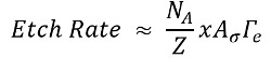
N, A는에 천트 종의 표면 농도이고, Z는 가능한 반응 부위의 표면 농도 x는 휘발성 에칭 관한 화학량 인자반응물에 대해 생성 된 제품은 σ는 전자 수증기 충돌에서 원하는 에칭 종의 발생 확률을 나타내고, Γe 표면에서의 전자 플럭스이다. Z가 거의 일정 및 NA보다 훨씬 더 큰 것으로 가정하는 동안 X와 σ의 요인은, 화합 것으로 간주됩니다. 더 자세한 사항은 우리의 이전 작품에서 찾아 볼 수있다. (11)

이 기사에서는 절차는 개별 탄소 나노 튜브 대량으로 (입방 수십 마이크로 미터) 물질 제거에 이르기까지 공장 지역에 SEM 내에서 저압 수증기를 사용하는 탐구한다. 여기서는 삭감 영역 직사각형 수평 라인 스캔, 및 전자 빔의 래스터 화 소프트웨어 제어를 사용하여 ESEM을 사용 밀 CNT 숲에 사용되는 방법을 보여준다. 재료 목록에 설명 된대로 추가 소프트웨어 및 하드웨어, 패턴 생성에 필요합니다. 강조는 상대적 제거에 배치됩니다LY 큰 (입방 마이크론의 100 년대)는 CNT 숲에서 재료 볼륨 조정, 다음의 처리 조건은 상대적으로 공격적이다.

샘플 및 샘플 스텁을 처리 할 때, 일회용 니트릴 장갑을 착용하는 것이 중요하다. 이 스터브 또는 샘플에 옮기고, 그 결과 펌프의 효율이 저하되는 오일을 방지 할 것이다.

Protocol

밀링 용 CNT 숲 샘플 1. 준비 CNT 합성 원자 층 증착 (13) 또는 다른 물리적 기상 증착법을 사용하여 열 산화 실리콘 웨이퍼 상에 산화 알루미늄 (알루미나)의 10 nm의 증착. 금고 (14) 또는 다른 물리적 증착법을 스퍼터링 법에 의해 알루미나 지지체 층에 철 1 내지. 이러한 열적 화학적 기상 증착 (15)로 확립 …

Representative Results

ESEM 기술은 CNT 숲 열 CVD (15, 16)하여 합성 밀에 사용 하였다. 포리스트 내에서 몇 탄소 나노 튜브의 선택 영역 제거는 그림 2 (11)에 표시됩니다. 이 데모를 들어, 매개 변수는 5 kV의, 3의 스폿 사이즈, 11 파, 170,000X 배율을 포함, 2 밀리 드웰 시간, 30 μm의의 구멍. <p class="jove_content" fo:keep-together.within-pa…

Discussion

이 프로토콜은 CNT 숲에서 기능 비교적 큰 (마이크론 스케일) 밀링에 대한 모범 사례를 자세히 설명합니다. 일반적으로, 물질 제거 속도가 가속 전압, 스포트 크기, 개구 직경을 감소시킴으로써 감소 될 수있다. 포리스트 내의 특정 CNT 트림 조건 5 kV로, (3)의 스폿 크기, 직경이 50 ㎛ 이하이다 개구를 포함 권장. 전자선 동봉 영역 한번만 래스터 것을 감소 ​​사각형 영역을 사용하여 밀링 기술은 자?…

Divulgations

The authors have nothing to disclose.

Acknowledgements

This work was supported by the Air Force Office of Scientific Research grant FA9550-16-1-0011 and University of Missouri startup funds. The authors would like to thank the University of Missouri Electron Microscopy Core facility for assistance with SEM imaging and use of patterning equipment and software.

Materials

100 mm diameter silicon wafer with 1 micron thermal oxide University Wafer Beginning substrate
Iron sputter target Kurt J. Lesker EJTFEXX351A2 Sputter target 
Savannah 200 Cambridge For atomic layer deposition of alumina
Quanta 600F Environmental SEM FEI Environmental scanning electron microscope used to support a low-pressure water vapor ambient environment for CNT forest milling
xT Microscope Control software FEI 4.1.7 Control software used on Quanta 600F ESEM
Nanometer Pattern Generation System – Software JC Nabity Lithography Systems Version 9 Software used for electron-beam lithography
Dedicated computer with PCI516 Lithography board Equipment used for electron-beam lithography
DesignCAD software V 21.2 Optional equipment used to generate patterns for electron-beam lithography
E-beam lithography mount Ted Pella 16405 Electron beam lithography mount with a Faraday cup and gold nanoparticles on carbon tape
Picoammeter Keithley 6485 Used with the Faraday cup to quantify beam current
12.7 mm diameter SEM stub Ted Pella 16111 SEM stub
45 degree pin stub holder Ted Pella 15329 Optional equipment used to mill the cross section of a CNT forest

References

  1. Labunov, V., et al. Femtosecond laser modification of an array of vertically aligned carbon nanotubes intercalated with Fe phase nanoparticles. Nanoscale Res Lett. 8 (1), 375-375 (2013).
  2. Lim, K. Y., et al. Laser Pruning of Carbon Nanotubes as a Route to Static and Movable Structures. Adv Mater. 15 (4), 300-303 (2003).
  3. Raghuveer, M. S., et al. Nanomachining carbon nanotubes with ion beams. Appl Phys Lett. 84 (22), 4484-4486 (2004).
  4. Sears, K., Skourtis, C., Atkinson, K., Finn, N., Humphries, W. Focused ion beam milling of carbon nanotube yarns to study the relationship between structure and strength. Carbon. 48 (15), 4450-4456 (2010).
  5. Smith, B. W., Luzzi, D. E. Electron irradiation effects in single wall carbon nanotubes. J Appl Phys. 90 (7), 3509-3515 (2001).
  6. Banhart, F., Li, J., Terrones, M. Cutting Single-Walled Carbon Nanotubes with an Electron Beam: Evidence for Atom Migration Inside Nanotubes. Small. 1 (10), 953-956 (2005).
  7. Krasheninnikov, A. V., Banhart, F., Li, J. X., Foster, A. S., Nieminen, R. M. Stability of carbon nanotubes under electron irradiation: Role of tube diameter and chirality. Phys Rev B. 72 (12), 125428 (2005).
  8. Royall, C. P., Thiel, B. L., Donald, A. M. Radiation damage of water in environmental scanning electron microscopy. J Microsc. 204 (3), 185-195 (2001).
  9. Yuzvinsky, T. D., Fennimore, A. M., Mickelson, W., Esquivias, C., Zettl, A. Precision cutting of nanotubes with a low-energy electron beam. Appl Phys Lett. 86 (5), 053109 (2005).
  10. Liu, P., Arai, F., Fukuda, T. Cutting of carbon nanotubes assisted with oxygen gas inside a scanning electron microscope. Appl Phys Lett. 89 (11), (2006).
  11. Rajabifar, B., et al. Three-dimensional machining of carbon nanotube forests using water-assisted scanning electron microscope processing. Appl Phys Lett. 107 (14), 143102 (2015).
  12. Lassiter, M. G., Rack, P. D. Nanoscale electron beam induced etching: a continuum model that correlates the etch profile to the experimental parameters. Nanotechnology. 19 (45), 455306 (2008).
  13. Amama, P. B., et al. Influence of Alumina Type on the Evolution and Activity of Alumina-Supported Fe Catalysts in Single-Walled Carbon Nanotube Carpet Growth. ACS Nano. 4 (2), 895-904 (2010).
  14. Almkhelfe, H., Carpena-Nunez, J., Back, T. C., Amama, P. B. Gaseous product mixture from Fischer-Tropsch synthesis as an efficient carbon feedstock for low temperature CVD growth of carbon nanotube carpets. Nanoscale. , (2016).
  15. Maschmann, M. R., Ehlert, G. J., Tawfick, S., Hart, A. J., Baur, J. W. Continuum analysis of carbon nanotube array buckling enabled by anisotropic elastic measurements and modeling. Carbon. 66, 377-386 (2014).
  16. Maschmann, M. R., et al. Visualizing Strain Evolution and Coordinated Buckling within CNT Arrays by In Situ Digital Image Correlation. Adv Funct Mater. 22 (22), 4686-4695 (2012).
  17. Abadi, P. P. S. S., Maschmann, M. R., Baur, J. W., Graham, S., Cola, B. A. Deformation response of conformally coated carbon nanotube forests. Nanotechnology. 24 (47), 475707 (2013).
  18. Brieland-Shoultz, A., et al. Scaling the Stiffness, Strength, and Toughness of Ceramic-Coated Nanotube Foams into the Structural Regime. Adv Funct Mater. 24 (36), 5728-5735 (2014).
  19. Maschmann, M. R., Dickinson, B., Ehlert, G. J., Baur, J. W. Force sensitive carbon nanotube arrays for biologically inspired airflow sensing. Smart Mater Struct. 21 (9), 094024 (2012).
  20. Maschmann, M. R., et al. In situ SEM Observation of Column-like and Foam-like CNT Array Nanoindentation. ACS Appl Mater Inter. 3 (3), 648-653 (2011).
  21. Pathak, S., Raney, J. R., Daraio, C. Effect of morphology on the strain recovery of vertically aligned carbon nanotube arrays: An in situ study. Carbon. 63, 303-316 (2013).
  22. Pour Shahid Saeed Abadi, P., Hutchens, S. B., Greer, J. R., Cola, B. A., Graham, S. Effects of morphology on the micro-compression response of carbon nanotube forests. Nanoscale. 4 (11), 3373-3380 (2012).
  23. Maschmann, M. R. Integrated simulation of active carbon nanotube forest growth and mechanical compression. Carbon. 86, 26-37 (2015).
check_url/fr/55149?article_type=t

Play Video

Citer Cet Article
Brown, J., Davis, B. F., Maschmann, M. R. Precision Milling of Carbon Nanotube Forests Using Low Pressure Scanning Electron Microscopy. J. Vis. Exp. (120), e55149, doi:10.3791/55149 (2017).

View Video