Automation is key to upscaling and cost management in cell manufacturing. This manuscript describes the use of a counterflow centrifugal cell processing device for automating the buffer exchange and cell concentration steps for small-scale bioprocessing.
Successful commercialization of gene and cell-based therapies requires manufacturing processes that are cost-effective and scalable. Buffer exchange and product concentration are essential components for most manufacturing processes. However, at the early stages of product development, these steps are often performed manually. Manual dead-end centrifugation for buffer exchange is labor-intensive, costly, and not scalable. A closed automated system can effectively eliminate this laborious step, but implementation can be challenging. Here, we describe a newly developed cell processing device that is suitable for small- to medium-scale cell processing and aims to bridge the gap between manual processing and large-scale automation. This protocol can be easily applied to various cell types and processes by modifying the flow rate and centrifugation speed. Our protocol demonstrated high cell recovery with shorter processing times in comparison to the manual process. Cells recovered from the automated process also maintained their proliferation rates. The device can be applied as a modular component in a closed manufacturing process to accommodate steps such as buffer exchange, cell formulation, and cryopreservation.
The landscape of modern medicine has transformed rapidly through recent developments in gene and cell-based therapies (GCT). As one of the fastest growing fields in translational research, the GCT sector also faces unique and unprecedented challenges. In addition to robust clinical outcomes, efficient and cost-effective manufacturing processes are essential for the commercial success of GCT, which is particularly difficult to achieve in small-scale manufacturing1. The cost of time, labor, and quality assurances are magnified when each batch of cells only produces a few doses for one patient instead of hundreds or thousands. Unlike allogeneic cell therapies in which the manufacturing processes are more akin to the production of antibodies and recombinant proteins, autologous cell therapies are typically produced as small-scale operations1. As a relatively new phenomenon in biopharmaceutical manufacturing2, options for small-scale cell processing are currently quite limited.
Buffer exchange is essential to cell manufacturing. It is one of the downstream processes where cells are removed from culture media and concentrated for cryopreservation or infusion. Currently, small-scale cell manufacturing often applies processes similar to those in the academic research setting and relies on specialized clean rooms to maintain sterility3. Manual downstream processes often use benchtop centrifuges to pellet and resuspend cells for volume reduction and buffer exchange. These open processes are costly (i.e., labor and clean room maintenance) and have limited manufacturing capacity, which are not ideal for commercial production2,3.
Implementing automation has been proposed as a solution to improve manufacturing efficiency and achieving commercial scale productions2. Sterility cannot be achieved in cell-based products through traditional methods used for biologics, such as gamma irradiation or terminal end filtration. Instead, an automated closed system is deployed to reduce risks of contamination and operators relying on clean rooms to maintain sterility4. Process automation also addresses the issue of scalability by either having multiple systems running in parallel (scale-out) or increasing the processing capacity of an individual device (scale-up), which in turn minimizes the variability between operators. Furthermore, cost modelling analysis of autologous therapies suggests that automation may reduce the cost of manufacturing5,6. However, no cost benefit was found in an autologous stem cell clinical trial where an automated manufacturing platform was used7, suggesting that the cost benefit of automation may depend on the individual manufacturing process.
There are different strategies in which automation can be introduced into an existing manufacturing process. This can be achieved either by implementing a fully integrated platform or a modular-based processing chain. There are several fully integrated platforms commercially available for autologous cell manufacturing, such as CliniMACS Prodigy (Miltenyi Biotec), Cocoon (Octane Biotech), and Quantum (Terumo BCT). These integrated platforms, which are often described as "GMP-in-a-box", have low demands on infrastructure and are easy to operate. However, the manufacturing capacity of a fully integrated setup may be restricted by the incubator attached to the system. For example, the culturing capacity of Prodigy is limited to its 400 mL chamber8 and the Quantum cartridge has a limiting surface area set to 2.1 m2 (equivalent to 120 T175 flasks)7, which may not be sufficient for patients requiring higher cell doses9,10. Additionally, Prodigy and Quantum have a common attribute that limits their use: the operational unit is occupied by a single batch of cells throughout the cell expansion period, thus limiting the number of batches that can be manufactured by each unit11. The modular approach to automation is to create a manufacturing chain with multiple modular units that simulates the commercial manufacturing process12,13. This approach, which separates the culture device from the cell washing device, can thereby maximize manufacturing efficiency. An ideal processing device would be one that is adaptable and scalable to manufacturing needs12.
Counterflow centrifugation (CFC) technology, which dates back to the 1970s, has had a long history in cell processing14. It achieves cell concentration and separation by balancing centrifugal force with a counterflow force. Typically, a cell suspension enters from the narrow end of a cell chamber under a constant flow rate while subjected to a centrifugal force (Figure 1A). The flow of the fluid is exerted in the opposite direction to the centrifugal force. This is referred to as the counterflow force, which forms a gradient within the cell chamber. The counterflow force then decreases as the cell chamber widens away from the tip of the cone-shaped cell chamber. Cells with higher density and larger diameter have a higher sedimentation rate, and thus they reach force equilibrium towards the tip of the cone-shaped cell chamber. Smaller particles may reach equilibrium towards the base of the chamber or be too small to be retained in the chamber and will be washed away. The CFC technology is mostly known for its application in processing blood apheresis products, such as isolating monocytes for dendritic cell therapies15,16. In terms of buffer exchange, the CFC technology has only been applied in large-scale manufacturing17 and has yet to be used for the smaller scale manufacturing of autologous cell therapies.
To address the need of a suitable device for small-scale cell manufacturing, an automated CFC device (See Table of Materials), was recently developed18. The automated cell processing device uses counterflow centrifugation technology to remove cell debris and facilitate buffer exchange. The device performs buffer exchange with a single-use kit that can be sterile-connected to a cell transfer bag, which allows the cells to be processed within a sterile, enclosed system. Here, we investigate the use of a counterflow centrifugal device to perform buffer exchange in mammalian cell cultures in automated protocols. In this study, we tested the buffer exchange protocol using Jurkat cells and mesenchymal stromal cells (MSCs) to model nonadherent and adherent cell types, respectively. Jurkat cells are immortalized T cells often used for the study of acute T cell leukemia19,20. MSCs are adult stem cells that have been studied in human clinical trials for a wide range of diseases9.
1. Preparation of reagents and cells for buffer exchange
2. Program for automated buffer exchange protocol
3. Setting up the machine
4. Automated buffer exchange
5. Collecting and sampling the cells
6. Process validation
In this protocol, we used Jurkat cells and MSCs as representative examples to demonstrate the automated buffer exchange process. During the process, Jurkat cells and MSCs shared the same processing steps with differences in centrifugal force and pump speed that control the flow rate (Table 1). Figure 2 shows representative images captured by the camera of how the fluidized cell bed may appear during the buffer exchange process. Typically, the fluidized cell bed will resemble the image in Figure 2A, where cells accumulate in the middle and towards the front of the cone with a small space at the tip of the chamber, where cells do not accumulate and the opening of the cell loading inlet is visible. The fluidized cell bed may be compressed (Figure 2B) when introducing new buffer that is at a different viscosity or density. In this protocol, the pump speed was lowered from 30–35 mL/min to 20 mL/min at the start of the washing step. Once the chamber was filled with the new buffer, the pump speed was returned to normal to prevent pelleting cells at the tip of the chamber. A high flow rate (Figure 2C) may be applied to select for live cells because dead cells are smaller and lighter and can be forced out of the chamber by increasing the flow rate.
The automated process of buffer exchange was achieved by first concentrating the cells, then introducing the wash buffer, which was around 10x of the volume of the fluidized cell bed. The cells were then formulated to the desired volume. These three processing steps were designed to follow the same principles as a manual buffer exchange. Typically, a two-cycle centrifugation (200 x g, 5 min) is used to perform manual buffer exchange, in which cells are pelleted to concentrate, resuspended to wash, then centrifuged again and resuspended to the final volume. The processing time of the automated processes was shorter compared to the manual ones (Figure 3). The recovery rate between manual and automated processes were similar for both Jurkat cells and MSCs, and cell viability was not affected by the process (Figure 4). The cell quality was verified by cell proliferation (MTS assay) and cytokine/enzyme production. The recovered cells showed similar proliferation rates between the manual and the automated processes (Figure 5A). The level of interleukin-2 production from Jurkat cells and IDO activity of MSCs were also comparable between the two groups (Figure 5B and 5C).
Step Number | Description | Open valves | Centrifuge speed (g) | Pump speed (ml/min) | Triggers | |
1 | Prime tubing from B to A | A, B, K | 10 | 50 | Volume: 45 ml | |
2 | Fill bubble Trap from A to B | A, B, K | 100 | 50 (reverse) | Volume: 10 ml | |
3 | Prime tubing A to D | A, D, K | 100 | 50 (reverse) | Volume: 2 ml | |
4 | Prime tubing J to K | J, K | 100 | 50 | Volume: 3 ml | |
5 | Load cells – initial start D to G | D, K, G | 1600 (Jurkat) 1500 (MSCs) | 25 (Jurkat) 30 (MSCs) | Volume: 100 ml | |
6 | Load cells with bubble detect [At the detection of bubble/ empty tubing, the program will pause and wait for operator’s command, press ‘pause’ or ‘next’] | A, D, K | = last step | 30 (Jurkat) 35 (MSCs) | Bubble sensor D | |
7 | Empty remaining media on port D tube | A, D, K | = last step | = last step | Volume: 1.5 ml | |
8 | Wash cells 1 | A, B, K | = last step | 20 | Volume: 20 ml | |
9 | Ramping up washing speed | A, B, K | = last step | 35 | Timer: 5 seconds speed ramping | |
10 | Wash Cells 2 | A, B, K | = last step | = last step | Volume: 20 ml | |
11 | Prepare to harvest | J, K | = last step | = last step | Timer: 2 seconds | |
12 | Recover cells to output and dilute to target volume | B, J, K | = last step | 60 (Reverse) | Volume: 10 ml | |
Note: ‘= last step’ is a setting option for centrifuging speed and pump speed in the GUI. |
Table 1: Automated buffer exchange GUI setup for Jurkat cells and MSCs.
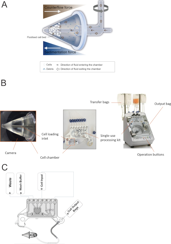
Figure 1: Counterflow centrifugal cell processing system. (A) A schematic diagram illustrating the principle of counterflow centrifugation. The counterflow force is present in a gradient within the cell chamber. While centrifuging (grey arrow), cells with larger diameters receive a higher sedimentation force, in which the cells reach force equilibrium towards the narrow end of the chamber, forming a fluidized cell bed. Cell debris and small particles that are too small to remain in the chamber are washed away. (B) The counterflow centrifugal processing system consists of the processing device and the single-use processing kit. (C) The single-use kit configuration for the buffer exchange protocol. Please click here to view a larger version of this figure.
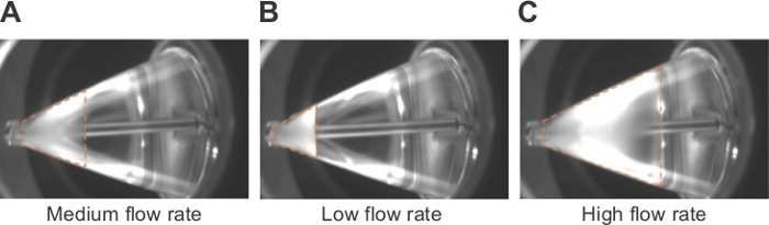
Figure 2: Fluidized cell bed in the cell chamber. Representative images of a fluidized cell bed under (A) medium, (B) low, and (C) high flow rate. The dotted line indicates the area of the fluidized cell bed within the chamber. Please click here to view a larger version of this figure.
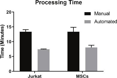
Figure 3: Comparison of cell processing time of Jurkat cells and MSCs with manual and automated processing. (n = 3–4 in each group, data are presented as mean ± SD). Please click here to view a larger version of this figure.
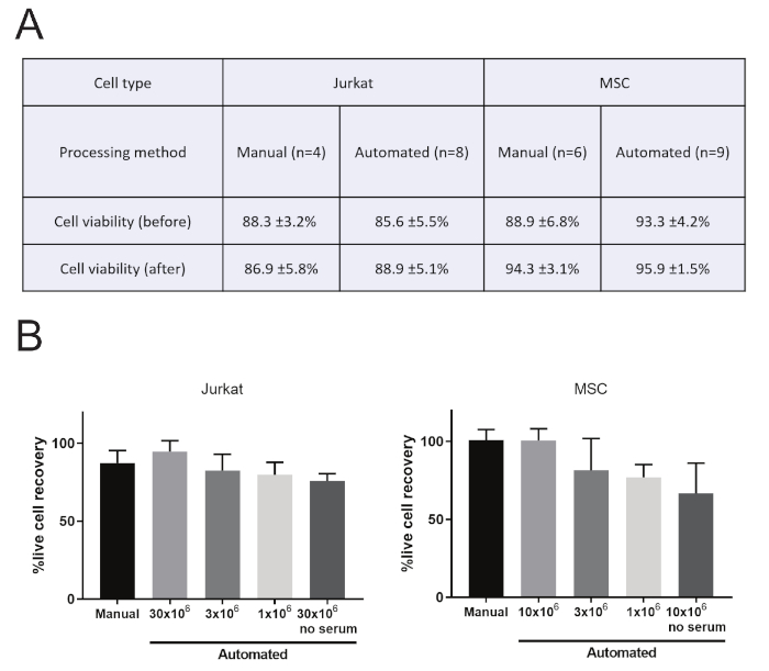
Figure 4: Comparison of cell viability and live cell recovery of Jurkat cells and MSCs with manual and automated processing. Cell viability (A) and live cell recovery (B) were measured by trypan blue exclusion assay using an automated cell counter. Live cell recovery was reduced in the absence of serum or when only 3 x 10⁶ or 1 x 10⁶ cells were processed. (n = 4–9 in each group, data are presented as mean ± SD). Please click here to view a larger version of this figure.
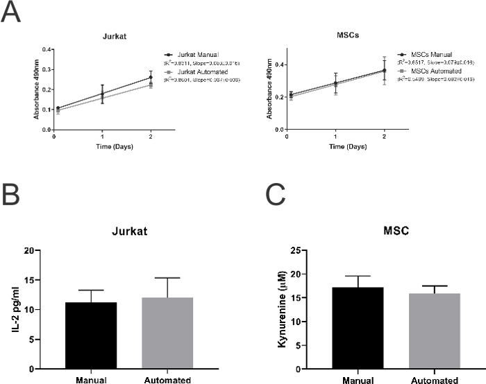
Figure 5: Cell proliferation and cell function from manual and automated processing. (A) MTS assay of Jurkat cells and MSCs were performed at 2, 24, and 48 h after buffer exchange. The quality of recovered cells was quantified by Interleukin-2 production from Jurkat cells (B), and IDO activity in MSCs (C). (n = 4–8 in each group, data are presented as mean ± SD). Please click here to view a larger version of this figure.
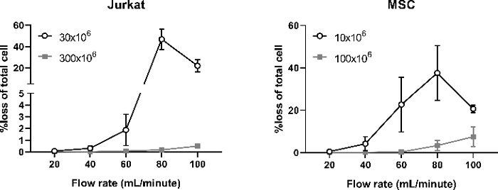
Figure 6: Fluidized cell bed stability at various flow rate. Two processes were performed for each cell type. In one process, either 3 x 10⁷ Jurkat cells or 1 x 10⁷ MSCs. In the second process, 10x the number of cells were used. In both processes, 10 mL of cell elutriate was collected from port A at various flow rates using the centrifuging speed indicated in this protocol (1,600 x g for Jurkat cells and 1,500 x g for MSCs). The number of cells in the elutriate was determined and presented as percentage of the total amount of cells loaded in the chamber. (n = 3 for each group, data are presented as mean ± SD). Please click here to view a larger version of this figure.
The automated buffer exchange protocol described is simple and user friendly. Nevertheless, there are a few key steps in this protocol that are critical and require particular attention. In our experience, when processing larger cells such as MSCs (average diameter 10–15 µm) each run should include at least 1 x 10⁷ cells to achieve optimal cell recovery (Figure 4B). Processing smaller cells, such as Jurkat cells (average ~10 µm diameter), requires around 3 x 10⁷ cells to achieve a stable fluidized cell bed (Figure 4B). When the cell number is too low, cells are more likely to be removed from the fluidized bed, which will affect the final cell recovery. Additionally, we compared cell loss rates at different pump speeds when a constant centrifugal speed is applied. Here, we observed that the cell loss increased with the flow rate (Figure 6), which is due to the increasing instability of the fluidized bed at higher flow rates. However, the percentage of cell loss was lower when 10x the number of cells were loaded into the chamber, which suggests that a higher pump speed can be applied when processing a larger number of cells to allow faster processing. In step 5 of the process, 100 mL of culture media was recirculated from the chamber back to the cell transfer bag to allow the fluidized bed to form and stabilize prior to volume reduction and buffer exchange. If the cell concentration is low (e.g., below 0.2 x 10⁶/mL), the recirculation step may need to be extended to allow enough cells to form the fluidized cell bed. Likewise, if the cell concentration is high, the recirculation step can be shortened.
The presence of serum in the wash buffer is also critical for cell recovery. Previous studies have shown that hydrodynamic stress can cause necrotic cell death in the absence of buffering proteins22,23. The flow dynamic of the counterflow centrifugal system is quite complex. In this protocol, cell recovery rates dropped to around 70% when the process was performed in the absence of serum (Figure 4B). Although the exact mechanism is not clear, the presence of serum in culture media or albumin in wash buffers was able to mitigate the potential mechanical damage to the cells. For applications requiring serum-free buffers, hydroxyethyl starch and dextran 40 are examples of non-protein additives that are often used in cell manufacturing to protect against hydrodynamic stress24,25.
Counterflow centrifugation technology has been used in large-scale biopharmaceutical manufacturing and blood product processing17. The applications of CFC technology in small-scale cell manufacturing (i.e., 0.1–10 L) are often limited to isolating mononuclear cells from apheresis products, such as the Elutra (Terumo BCT)26, in which additional manual intervention is required to perform wash and concentrate steps. Other small-scale cell processing platforms include membrane filtration-based buffer exchange systems such as the LOVO (Fresenius Kabi)27 and vertical centrifugation separation such as the Sepax (GE Healthcare)28. Although it is difficult to perform a direct comparison between devices, one of the advantages of this counterflow centrifugal device is its capacity to deliver very small output volumes (minimum 5 mL), which is the smallest among currently available cell processing platforms. The small output volume is suitable for applications such as formulating cells for local injections29 or infusions for neonates30. The camera embedded in the device is also a unique feature that provides visualization of the fluidized cell bed during the process development stage.
One of the limitations of the CFC technology is that it is sensitive to the size and density of the cells. When setting up a buffer exchange protocol for a different cell type, the protocol presented here should serve as a guideline for users to optimize according to their needs, keeping in mind the size of their cells of interest and the density of their cell suspension. Although the current protocol is usable for processing up to 5 L of media, the processing time will be substantially extended (i.e., 1–2 h). It is important to note that the impact of extended processing time on cell quality has not been examined in this current study.
Future studies will evaluate the impact of processing speed and processing time on cell function to determine the maximum processing capacity of the device. Furthermore, future studies may explore other applications such as the removal of dimethyl sulfoxide (DMSO) from cryopreserved products and selective removal of dead cells.
The authors have nothing to disclose.
This work is supported by the Victorian Government's Operational Infrastructure Support Program, and the Victorian Government Technology Voucher provided by the Department of Economic Development, Jobs, Transport and Resources. RL is the recipient of a National Health and Medical Research Council Career Development Fellowship. AL is the recipient of an Australian Postgraduate Award.
20 ml Luer lock syringes | BD | 302830 |
20% Human serum albumin (HSA) | CSL Behring | AUST R 46283 |
4-(Dimethylamino)benzaldehyde | Sigma-Aldrich | 156477-25g |
500ml IV saline bag | Fresenius Kabi | K690521 |
Antibiotic-Antimycotic | Thermo Fisher Scientific | 15240112 |
Automated cell counter (Countess) | Thermo Fisher Scientific | N/A |
Cell counting chamber slides | Thermo Fisher Scientific | C10228 |
Cell stimulation cocktail (500x) | Thermo Fisher Scientific | 00-4970-93 |
Cell transfer bags | Terumo | T1BBT060CBB |
CellTiter AQueous One Solution Cell Proliferation Assay (MTS) | Promega | G3582 |
Centrifuge | Eppendorf | 5810R |
DMEM: F12 media | Thermo Fisher Scientific | 11320082 |
EnVision plate Reader | Perkin Elmer | N/A |
Fetal bovine serum (FBS) | Thermo Fisher Scientific | 10099141 |
Human Interleukin 2 (IL2) Kit | Perkin Elmer | Al221C |
Luer (female) fittings | CPC | LF41 |
PC laptop or PC tablet device | ASUS | N/A |
Plate reader (SpectraMax i3) | Molecular Device | N/A |
Recombinant Human IFN-γ | PeproTech | 300-02 |
Rotea counterflow centrifuge cell processing device | Scinogy | N/A |
Rotea single-use processing kit | Scinogy | N/A |
RPMI media | Thermo Fisher Scientific | 11875119 |
Surgical scissors | ProSciTech | 420SS |
Trichloroacetic acide | Sigma-Aldrich | T6399-250g |
Trypan Blue stain | Thermo Fisher Scientific | T10282 |
Trypsin digestion enzyme (TrypLE Express Enzyme) | Thermo Fisher Scientific | 12604013 |