CAUTION: Please consult all relevant material safety data sheets (MSDS) before use. Also, complete relevant training and utilize appropriate precautions for hazards which may include but are not limited to chemicals used, high voltage, vacuum, cryogens, pressurized gasses, nanoparticles, lasers, and ionizing radiation. Ensure authorization and training for use of all equipment. Please use all appropriate safety practices dictated in the operating procedures (radiation monitoring device, personal protective equipment, etc.). NOTE: All parameters given in this protocol are valid for the instruments and models indicated here. 1. In situ ion irradiation TEM experimental design NOTE: There are many variables that can be changed resulting in a large potential experimental space. Designing systematic experiments such that they will answer specific scientific questions will result in the most success. First, choose appropriate ion species and energies that will model the system to be emulated. Ion species selection NOTE: Ion interaction with materials is complex and the details are beyond the scope of this document. There exist several publications detailing ion interaction in solids23, or more specifically with metals24, and semiconductors25. Space radiation environments consist of a spectrum of ion energies and masses, which can be effectively modeled with light and heavy ions. Nuclear systems can be emulated using a combination of heavy ion irradiation and gas implantation. Heavy ion irradiation simulates the displacement cascade damage induced by neutrons and high energy fission or radioactive decay products. He is often generated in nuclear materials by either transmutation reactions or radioactive decay. Choose an element to implant, based upon chemistry, damage type, and matching neutron spectrum. To minimize chemistry effects due to ion implantation, self-ion irradiation is often utilized, where the ion selected is the same as the material to be examined. Alternatively, doping studies can select specific ions for implantation. Damage type is determined by the kinetic energy of the ions with higher energies producing larger damage. For a fixed energy, light ions can be chosen to produce Frenkel pairs, heavy ions for damage cascades, and heaviest ions for ion tracks26. To simulate neutron damage, choose an ion that matches primary knock-on atom (PKA) displacements with the neutron spectrum of interest27. NOTE: Not all elements form stable negative ions suitable for use in Tandem accelerators. See Figure 1 for a list of all ions successfully run in the I³TEM facility. For background on accelerator operations and a list of 6 MV Tandem compatible elements with stable negative ions please refer to Middleton’s cookbook28. Figure 1: Ions run to date (highlighted in blue), charge states, and energy ranges in I³TEM. Please click here to view a larger version of this figure. Ion energy selection using the stopping and range tables in SRIM NOTE: The Stopping and Range tables provide a quick method for determining the depth of penetration of ions into a material. The stopping power, dE/dx, describes the energy (dE) an ion loses per unit distance (dx) traveled in a solid. The stopping power consists of two components: 1) nuclear stopping, the energy lost to elastic collisions with target atoms, and 2) electronic stopping, the energy lost due to interactions with the target atom electrons. The following procedure describes the implementation of a typical SRIM table. In SRIM software select Stopping / Range Tables. Select the ion to be implanted and the target material. Multiple target elements may be selected for a compound target. NOTE: A calculated density is provided but is usually very inaccurate and a value should be entered manually. Select Calculate Table to see a table of ion energies vs projected range, lateral and longitudinal straggling in the material. NOTE: For implantation experiments, the peak stopping range should be within the foil thickness. Energies above 6 MV are possible with multiple charge states. Where the ion energy, E, is approximately determined by: Equation (1) Where M1 is the mass of the selected ion, MT is the total mass of the compound in the source (MT = M1 for single element sources), q is charge state, VT is terminal voltage and VS is source potential. NOTE: Charge states also influence beam current, which will affect fluence achievable and the time of exposure for experiments (see Equations 2, 3). Ion fluence and flux selection using SRIM NOTE: Verify the penetration depth profile for the energy used in 1.2 by using SRIM. Decide on a target ion concentration (dose, fluence) or damage level based on relevant literature. Damage level is often reported in dpa and does not reflect the final number of defects, but is the average number of displacements without accounting for defect annihilation at free surfaces or recombination. Other environmental conditions such as temperature or mechanical load may be applied simultaneously. These may affect the damage and microstructural evolution mechanisms and should be considered. The following is a description of how to use SRIM to calculate damage or fluence. There are alternate methods to calculate damage22, but the method described is widely used and considered simpler and quicker. It is highly recommended that these guidelines are followed for the relevant radiation conditions, and most importantly that the simulation parameters are recorded and reported so that they can be reproduced. In SRIM software, select the ion to be implanted and the target material. Multiple target elements may be selected for a compound target. A calculated density is provided but is usually very inaccurate and a value should be entered manually. Select TRIM calculation type: “Ion Distribution and Quick Calculation of Damage” and “Quick K-P” damage model. NOTE: The vacancy.txt method provides a quick approximation of the damage profile that is sufficient for planning most I3TEM experiments. Stoller et al.21 detail how to use SRIM to implement the quick Kinchin-Pease equation to determine the dpa per ion per area in metal systems. There are competing arguments for the usage of “quick K-P” vs. “Full Cascade” options21,22, especially in ionic compounds containing elements with different threshold displacement energies. The authors recommend researching each of these methods to determine the most appropriate calculation method for reporting the final dpa in publications, depending on the specific sample type and experimental design. Set layer thickness the same as the TEM sample thickness (10‒150 nm). NOTE: The software will automatically divide the depth into 100 bins of equal size, so choosing a larger thickness will cause less accurate binning. Set the ion incidence angle to match experimental conditions (typically 60° from normal). NOTE: The ion beam is nearly normal to the electron beam in the TEM and typically the specimen is tilted towards the ion beam by 30°. See sections 3 and 4 for experimental configuration schematics. Choose a threshold displacement energy from a reputable literature source, such as ASTM E52129. Set the lattice and surface energy to zero. NOTE: Publications on both modeling30 and experimental work31 present threshold displacement energies on various materials. Zero lattice and surface energy are appropriate for most conditions, but for special cases, a value may need to be supplied21. Run the simulation. Check the VACANCY.txt file for damage events as a function of depth, both VACANACIES by IONS and VACANCIES by RECOILS for each depth. This file can be imported into a spreadsheet. NOTE: Using the vacancy.txt file may not be the most accurate method for calculating damage dose and should be considered a quick approximation21. Convert the units from (displacements/ion-Å) to (displacements/ion·cm). Then use the measured ion fluence to determine the dpa or determine the necessary ion fluence for a desired dpa (Equation 2, see section 3.1.5 and 3.2.5 for how to measure fluence). If damage rate (dpa/s) is desired, substitute flux (ions/cm2-s) for fluence. Equation (2) Calculate the time of exposure necessary for a target fluence. NOTE: Below are the relationships between these values where e is the electron charge and C is Coulombs (Equation 3). Some experiments range over several decades of fluence and thus a commensurate range of times with a given flux. For high fluence experiments, maximum flux is desired to minimize experiment time24. Due to the limiting speed of the gate valves and the Faraday cup actuator, low fluence requires a lower flux such that the exposure time can be achieved with sufficient precision: on the scale of seconds. High beam current can result in local heating of the sample which may change the diffusion properties and the observed microstructural evolution. In experiments utilizing high beam current, the sample should be cooled to room temperature and the temperature monitored with thermocouples during the irradiation. (Equation 3) TEM stage selection NOTE: Simple ion irradiation experiments can be performed on a single tilt holder. Depending on the material system and properties of interest, however, a variety of holders may be appropriate. It is possible to combine a variety of extreme environment components simultaneously with ion irradiation including conditions such as temperature, gas or liquid environment, and mechanical stress. Consider the use of cryogenic or heating holders. Temperature plays an important role in the diffusion of atoms. Implantation temperature can influence the type and intensity of damage. Cryo-holders or heating holders can be selected to maintain a desired temperature. Maintain room temperature with the use of a heating holder running chilled water. NOTE: For high temperature experiments samples should be mounted to a Mo grid or other thermally stable grids. Consider the use of double tilt or tomographic holders. Crystal orientation can be important to understand and is needed to obtain two beam condition conducive to quantifying dislocation loops or black spot densities. Double tilt or tomographic holders may be used for these cases. This would also be useful for examining radiation induced phase changes. Consider the use of environmental holders to expose the material to gas or liquid in situ. Specimen preparation for this type of experiment varies, can be very difficult, and is beyond the scope of this document32. Consider the use of stages specialized for mechanical testing including tension, compression, bend, fatigue, and creep. NOTE: Specific sample preparation is required for these types of experiments and is beyond the scope of this document33,34,35,36. Now that the ion species, ion energy, and target fluence have been determined, and specific holders for additional environmental complexity have been considered, the next step in designing ion irradiation experiments is preparing specimens for TEM. Careful preparation of the specimen is required to satisfy the geometric constraints for in situ ion irradiation TEM experiments. Several sample preparation methods are described below. 2. Preparation of thin sample and mounting on TEM grid NOTE: There are many ways to prepare a sample for TEM. The most appropriate method depends on starting sample geometry, material, and features of interest. For an extensive list and descriptions of preparation methods please refer to the sample preparation handbook for TEM37. Below are described three common methods. For magnetic materials a bonding method should be applied so the films or particles do not come off when subjected to the magnetic field in the TEM. Insulating substrates (i.e., oxides) should be avoided to minimize electrostatic expulsion due to ion beam induced charge. Drop casting of nanoparticles NOTE: This is the most straightforward method for TEM sample preparation for nanoparticles with diameter less than 200 nm. Several different support materials can be used including lacey carbon, polymer, and silicon nitride membranes. These materials may interact differently with the nanoparticles due to ligand interactions. Select whichever substrate results in well dispersed nanoparticles. Disperse nano-particles into a solvent such as alcohol, deionized water, or other combination until well mixed. Sonication may be used to break up additional agglomerates. The fluid concentration can be used to control the nanoparticle density on the grid. Use a Pipette to deposit dispersed particles onto the top side of a supported TEM grid. NOTE: Make sure the support side of the grid is facing upwards, so the nanoparticles stick on the top side of the grid. It is possible to take advantage of the capillary effect which drags the nanoparticles as the droplet dries. An off-center drop will result in a lower density of nanoparticles in the central irradiation area. Thin film float-off NOTE: This method requires a thin (<100 nm) film deposited on a dissolvable substrate such as salt or photoresist. A small portion of the sample is cleaved and placed into a solvent. As the substrate dissolves in the solvent, the thin film separates from the substrate and floats to the surface of the solution where it can be scooped onto a TEM grid. Prepare 50 mL of solvent solution in a Petri dish. NOTE: The solvent depends on the substrate for the thin film. NaCl substrates are common with water being the solvent. Alcohol can be added to the solution to change the surface tension. Too much alcohol will often cause the sample to sink, and too little alcohol will increase the surface tension making it difficult to transfer the film to the grid. Cleave or cut the substrate into approximately 1.5 mm × 1.5 mm sections. NOTE: The edges of the film are usually lower quality and should be avoided when possible. Using tweezers, insert the substrate, with film facing up, into the solution at an incident angle of about 30° (Figure 2a). Repeatedly retract and insert slowly until the film floats free (Figure 2b,c). The substrate can be set aside. Insert the TEM grid into the solution and bring below the film. Slowly lift the grid under the film until film is centered over grid. Quickly lift the grid out of the solution and the film will attach (Figure 2d). NOTE: If film is not well centered reinsert the grid and film into the solution to re-float the film and center as necessary. Be aware that the film can fold back on itself. Figure 2: Thin film float-off. Schematic showing (a) the insertion of a section of thin film, deposited on soluble substrate, into a solvent solution, (b) a cross sectional view of floating off the thin film by dissolving the adhesion layer of substrate, (c) a cross sectional view of thin film free floating on solution by surface tension, and (d) using TEM grid to lift the film from the solution. Please click here to view a larger version of this figure. Focused ion beam milling NOTE: Most bulk materials can be prepared by focused ion beam (FIB) milling and information detailing this process can be found in the handbook for TEM sample preparation37. FIB milling is a time consuming and involved process compared to the methods mentioned previously but is very short and easy compared to traditional hand polishing methods of preparing TEM specimens from bulk samples. It also has the advantage of high degree of control over the site which allows for selection of area of interest to investigate, such as boundaries or defects. The foils produced by FIB have residual ion irradiation damage induced by the ion beam milling process that will convolute quantification of the damage induced by the in situ irradiation38. Prepare the lift out. A variety of lift out strategies can be used to produce site-specific TEM foils in different geometries. For detailed methods please refer to publications for preparing samples in geometries such as: cross sectional39, plan view40, crack tips41, nano-pillars42, atom probe needles43, etc. Mount the foil. Ex situ lift outs can be placed on top of TEM grid similarly to thin films (Figure 3a). For specimens welded to a grid, the foil should be welded on the tip of a post on the face of the grid to avoid shadowing effects (Figure 3b). Avoid mounting in the V posts (Figure 3b: left and right). Perform a final polish to the lamella. Standard FIB thinning will result in ion beam damage to the specimen. This damage can be minimized by flush polishing at a very small glancing angle and by gentle milling with a low accelerating voltage. Alternatives to traditional final thinning via Ga+ ion beam include flash electropolishing44,45 and ion milling with Ar+46. Electro polishing NOTE: This is often the most preferred method for preparing single phase metallic specimens for in situ ion beam irradiation experiments from bulk material. It avoids the damage caused by FIB milling and traditional polishing techniques. However, the electrolyte solution, electric potential, and time for polishing are material specific and these parameters may be difficult to determine. Figure 3: Schematic showing TEM grids with specimens mounted on upper face to prevent shadowing. Grid with lacey carbon or thin film (a), half-moon grid with FIB lift-out welded to tip (b). Please click here to view a larger version of this figure. 3. Ion beam conditions and alignment Tandem accelerator NOTE: The Tandem accelerator is best suited for high energy ions 800 keV – 100 MeV. Sources of negative ions by cesium sputtering (SNICS) are frequently used to produce energetic metal ion beams and its operation is outside the scope of this document28. Adjustments and considerations for in situ TEM experiments are described below. Align the ion beam inside the TEM with steering magnets, bending magnets, and lenses so that irradiation events can be observed in situ. Perform final ion beam alignments by using a camera to view ion beam induced luminescence (IBIL) on a quartz-tipped TEM sample holder. Align the ion beam to be coincident with the cathodoluminescence produced by the electron beam with electron beam objective lens power matching that used in the experiment. Insert the Faraday cup upstream from the TEM to capture the ion beam, and take a reading to measure the beam current. Beam current measurements are necessary to calculate the fluence (Equation 3). For additional accuracy in the beam current measurement, insert a TEM holder equipped with a Faraday stage to measure the ion beam current in the specimen area of the TEM. If current needs to be monitored in real time, use the beam profile monitor (BPM). Power on the BPM then monitor the oscilloscope read out to perform current measurements. The BPM works by regularly chopping the beam which results in temporal distortion of the beam and is a qualitative measure of the beam current. NOTE: The ion beam current can drift so checking its stability throughout the experiment is advised. Measure the beam area using a burn spot. Burn spots can be used to confirm alignments in 3.1.1. Mount a piece of clear adhesive tape onto a single-tilt TEM specimen holder flat plate tip and expose to the electron beam and ion beam. Remove the tape and place onto a white background. To determine the area, photograph the burn spot with a ruler and import into an image processing software such as ImageJ47. Together with beam current, the beam area measurement can be used to determine the ion flux (Equation 2). Insert a calibration sample to visualize beam damage, which should appear as black spot contrast in kinematic bright field imaging conditions. Typically, Au or CuAu are chosen due to their readily apparent black spot formation and ease of sample preparation48. Colutron accelerator NOTE: The Colutron accelerator utilizes a gas-fed hot filament ion source49. It is possible to accelerate multiple gas species simultaneously, however, the mass to charge ratio of the two ion species must be equal in order for the bending magnet, steerers, and lenses to act identically; for example, 4He2+ and 2D1+. Perform SRIM calculations as described in section 1.2 to obtain the desired gas implantation energy. NOTE: The necessary bending magnet strength depends on the mass of the ion, its charge state, and the accelerating voltage. If the gas species has multiple isotopes, selecting the one which is most abundant will result in highest beam current. Also note that if the Tandem is active, this bending magnet will also act on its beam; additional corrections for the tandem will have to come after the Colutron beam is aligned. Steer the ion beam such that it is coincident with the electron beam, as described in step 3.1.1. Measure the beam current as described in step 3.1.2. Estimate beam area using a burn spot, as described in step 3.1.3. NOTE: This step can be performed simultaneously with the measurement of the ion beam from the Tandem accelerator. However, if the beam current from the Colutron accelerator is too high compared to the beam from the Tandem (> 3 orders of magnitude) it will cover up the signal and the measurements should be made separately. Perform final adjustments to steer the beam onto the TEM specimen as described in step 3.1.4. 4. TEM loading and imaging conditions Figure 4: TEM loading and imaging conditions. Overhead view of TEM holder with electron beam direction into the page with holder tilted 30° in positive X (a) and negative X (c). Cross sectional view down the axis of the holder with electron beam (green) and ion beam (blue) highlighted with holder tilted 30° in positive X (b) and negative X (d) for bottom side illumination of the ion beam. Highlighted area where both the electron beam and ion beam are not shadowed. Please click here to view a larger version of this figure. Specimen loading and geometric concerns Load grid onto the holder such that the specimen side of the grid is facing up and the grid is oriented to prevent shadowing effects when titled towards the ion beam (Figure 4a,c). NOTE: Figure 4b,d depicts a schematic of the ion beams path and electron beam path in the irradiation configuration where the effective experimental area is highlighted. Check for shadowing effects using an optical microscope. Tilt the holder 30° in the positive X direction as shown in Figure 4a,b. The overhead view will be parallel to that of the electron beam. Tilt the holder 60° in the negative X direction where the overhead view will be parallel to that of the ion beam. If the area of interest of the specimen is not visible in both orientation, there is a shadowing issue and the specimen must be moved. NOTE: For some holders the bottom of the stage has fewer shadowing issues and thus tilting to negative 30° such that the ion beam strikes the bottom side of the sample may be optimal (Figure 4d). Mount the specimen onto a TEM holder following the manufacturers guidelines for the specific holder. Load the holder into the TEM to begin the pump cycle. Wait for vacuum to stabilize and insert the holder. NOTE: When loading and unloading holders in the TEM, the valve to the beamline should be closed to prevent any loading induced vacuum crashes in the TEM from affecting the beamline. In the TEM control software, load the most recent alignment file for the accelerating voltage being used. Manually refine the alignments for the condenser lens and aperture, gun tilt and shift, and the objective lens. Find a region of interest on the specimen and adjust imaging conditions as described by Jenkins and Kirk50 for the type of analysis to be performed. Use brightfield kinematic conditions to image damage events. NOTE: For high Z number materials such as tungsten, an additional condenser lens may be engaged for additional brightness. NOTE: Low Z materials can be displaced by high energy electrons resulting in knock-on damage from the electron beam that may convolute the damage caused by the ions51. Using a low dose electron beam and limiting exposure to the specimen as well as using low dwell time scanning TEM will help to mitigate this. Tilt the holder the maximum safe distance (30° for most holders) up to 81° towards the ion beam. Apply any additional stressors such as heating, cooling, environmental, mechanical, etc. using the manufacturer recommended procedures specific to the chosen TEM holder. NOTE: For high magnification work, allow time for stage to stabilize so drift is not significant. Applied stressors may cause the specimen to deform as well. Open the TEM ion beam valve and remove the Faraday cup to expose the experimental specimen to ion irradiation. Pause exposure by inserting the Faraday cup and closing valves to the beam line. The Faraday cup should be inserted before closing the TEM valve to prevent damage to the valve. NOTE: The gun pressure in the TEM should be monitored such that it does not exceed the manufacturer-specified threshold for safe operation levels. It may be necessary to halt exposure to allow vacuum to recover if sample or stage is producing significant outgassing during ion beam exposure. Record images or videos to document the evolution of the microstructure. Additional imaging modes To map relative orientations of grains, use automated crystal orientation mapping (ACOM), a technique which allows for the identification of the crystallographic orientation of all crystallites with sizes as low as 10 nm. Software systems automate the collection of diffraction patterns with a precessed beam which are indexed resulting in an orientation map52. For ultrafast events, use the high-speed deflector. It is a magnetic lens that deflects projected electrons into different quadrants of the camera at fast rates effectively increasing frame time by an order of magnitude. It can be used to capture events that occur in the microsecond time scale in a single frame53. Perform electron tomography by capturing a tilt series of the specimen and subsequently perform reconstruction with software. This reveals the three-dimensional structure of the specimen and can be used to analyze volumetric distributions54. Make electron holography measurements by capturing a through-focus series. This measurement can be used to distinguish voids, bubbles, and nanoparticles55. Use weak beam dark field to view dislocations and damage caused by the ion beam. Two-beam condition for a single crystal is used to measure dislocation character and density50.
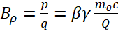 Equation (4)
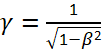 Equation (5)