Summary

القوة الذرية المجهرية المسافة البادئة القائمة على الكابولي: قياسات الخواص الميكانيكية على المستوى النانوي في الهواء والسوائل

Published: December 02, 2022
doi:

Summary

يتيح تحديد منطقة التلامس والقوة المطبقة بواسطة طرف مسبار مجهر القوة الذرية (AFM) على سطح العينة تحديد الخصائص الميكانيكية النانوية. تمت مناقشة أفضل الممارسات لتنفيذ المسافة البادئة النانوية القائمة على الكابولي AFM في الهواء أو السائل على العينات اللينة والصلبة لقياس معامل المرونة أو الخواص الميكانيكية النانوية الأخرى.

Abstract

يقيس مجهر القوة الذرية (AFM) بشكل أساسي التفاعل بين طرف مسبار AFM النانوي وسطح العينة. إذا كان من الممكن قياس القوة التي يطبقها طرف المسبار ومنطقة ملامسته للعينة ، فمن الممكن تحديد الخواص الميكانيكية النانوية (على سبيل المثال ، معامل المرونة أو يونغ) للسطح الذي يتم فحصه. يتم توفير إجراء مفصل لإجراء تجارب المسافة البادئة النانوية الكمية القائمة على الكابولي AFM هنا ، مع أمثلة تمثيلية لكيفية تطبيق هذه التقنية لتحديد الوحدات المرنة لمجموعة متنوعة من أنواع العينات ، بدءا من kPa إلى GPa. وتشمل هذه الخلايا الجذعية الوسيطة الحية (MSCs) والنوى في المخزن المؤقت الفسيولوجي ، والمقاطع العرضية لصنوبر لوبلولي المجففة المضمنة في الراتنج ، وصخر باكين بتركيبة مختلفة.

بالإضافة إلى ذلك ، يتم استخدام المسافة البادئة النانوية القائمة على الكابولي AFM لاستكشاف قوة التمزق (أي قوة الاختراق) لطبقات الفوسفوليبيد المزدوجة. تتم مناقشة الاعتبارات العملية المهمة مثل اختيار الطريقة وتطويرها ، واختيار المسبار ومعايرته ، وتحديد منطقة الاهتمام ، وعدم تجانس العينة ، وحجم الميزة ونسبة العرض إلى الارتفاع ، وتآكل الطرف ، وخشونة السطح ، وتحليل البيانات وإحصاءات القياس للمساعدة في التنفيذ السليم للتقنية. أخيرا ، يتم توضيح التوطين المشترك للخرائط الميكانيكية النانوية المشتقة من AFM مع تقنيات الفحص المجهري الإلكتروني التي توفر معلومات إضافية بشأن التركيب العنصري.

Introduction

يعد فهم الخواص الميكانيكية للمواد أحد أهم المهام الأساسية والأساسية في الهندسة. لتحليل خصائص المواد السائبة ، هناك العديد من الطرق المتاحة لتوصيف الخواص الميكانيكية لأنظمة المواد ، بما في ذلك اختبارات الشد1 ، واختبارات الضغط2 ، واختبارات الانحناء (الانحناء) ثلاثية أو أربع نقاط3. في حين أن هذه الاختبارات المجهرية يمكن أن توفر معلومات لا تقدر بثمن فيما يتعلق بخصائص المواد السائبة ، إلا أنها تجرى بشكل عام للفشل ، وبالتالي فهي مدمرة. بالإضافة إلى ذلك ، فإنها تفتقر إلى الدقة المكانية اللازمة للتحقيق بدقة في الخصائص الدقيقة والنانوية للعديد من أنظمة المواد التي تهم اليوم ، مثل الأغشية الرقيقة والمواد البيولوجية والمركبات النانوية. للبدء في معالجة بعض المشاكل المتعلقة بالاختبارات الميكانيكية واسعة النطاق ، وخاصة طبيعتها المدمرة ، تم اعتماد اختبارات الصلابة الدقيقة من علم المعادن. الصلابة هي مقياس لمقاومة المادة لتشوه البلاستيك في ظل ظروف محددة. بشكل عام ، تستخدم اختبارات الصلابة الدقيقة مسبارا صلبا ، عادة ما يكون مصنوعا من الفولاذ المقوى أو الماس ، لوضع مسافة بادئة في مادة. يمكن بعد ذلك استخدام عمق المسافة البادئة الناتج و / أو المساحة لتحديد الصلابة. تم تطوير عدة طرق ، بما في ذلك صلابة فيكرز4 و Knoop5 و Brinell6 . يوفر كل منها مقياسا لصلابة المواد المجهرية ، ولكن في ظل ظروف وتعريفات مختلفة ، وعلى هذا النحو ينتج فقط البيانات التي يمكن مقارنتها بالاختبارات التي يتم إجراؤها في ظل نفس الظروف.

تم تطوير المسافة البادئة النانوية الآلية لتحسين القيم النسبية التي تم الحصول عليها من خلال طرق اختبار الصلابة الدقيقة المختلفة ، وتحسين الدقة المكانية الممكنة لتحليل الخواص الميكانيكية ، وتمكين تحليل الأغشية الرقيقة. الأهم من ذلك ، من خلال استخدام الطريقة التي طورها أوليفر وفار7 لأول مرة ، يمكن تحديد معامل المرونة أو يونغ ، E ، لعينة المادة عن طريق المسافة البادئة النانوية الآلية. علاوة على ذلك ، من خلال استخدام مسبار بيركوفيتش الهرمي ثلاثي الجوانب (الذي تتطابق وظيفة منطقة طرفه المثالية مع وظيفة مسبار فيكرز الهرمي رباعي الجوانب)8 ، يمكن إجراء مقارنة مباشرة بين قياسات الصلابة النانوية والأكثر تقليدية على نطاق مصغر. مع نمو شعبية AFM ، بدأت المسافة البادئة النانوية القائمة على الكابولي AFM تحظى بالاهتمام أيضا ، خاصة لقياس الخواص الميكانيكية للمواد الأكثر ليونة. نتيجة لذلك ، كما هو موضح بشكل تخطيطي في الشكل 1 ، فإن التقنيتين الأكثر استخداما اليوم لاستجواب وقياس الخواص الميكانيكية النانوية هما المسافة البادئة النانوية الآلية (الشكل 1 أ) والمسافة البادئة النانوية القائمة على الكابولي AFM (الشكل 1 ب) 9 ، وهذا الأخير هو محور هذا العمل.

Figure 1
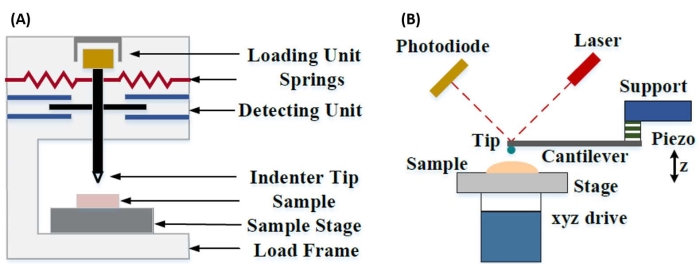
الشكل 1: مقارنة بين أنظمة المسافة البادئة النانوية القائمة على الكابولي و AFM. مخططات تخطيطية تصور أنظمة نموذجية لإجراء (أ) المسافة البادئة النانوية الآلية و (ب) المسافة البادئة النانوية القائمة على الكابولي AFM. تم تعديل هذا الرقم من Qian et al.51. اختصار: AFM = مجهر القوة الذرية. يرجى النقر هنا لعرض نسخة أكبر من هذا الرقم.

تستخدم كل من المسافة البادئة النانوية القائمة على الأجهزة و AFM مسبارا صلبا لتشويه سطح عينة محل الاهتمام ومراقبة القوة الناتجة والإزاحة كدالة للوقت. عادة ، يتم تحديد ملف تعريف الإزاحة للحمل المطلوب (أي القوة) أو (Z-piezo) من قبل المستخدم عبر واجهة البرنامج ويتم التحكم فيه مباشرة بواسطة الأداة ، بينما يتم قياس المعلمة الأخرى. الخاصية الميكانيكية التي يتم الحصول عليها غالبا من تجارب المسافة البادئة النانوية هي معامل المرونة (E) ، والذي يشار إليه أيضا باسم معامل يونغ ، والذي يحتوي على وحدات ضغط. معامل المرونة للمادة هو خاصية أساسية تتعلق بصلابة الرابطة ويتم تعريفه على أنه نسبة إجهاد الشد أو الانضغاط (σ ، القوة المطبقة لكل وحدة مساحة) إلى الإجهاد المحوري (ε ، التشوه النسبي على طول محور المسافة البادئة) أثناء التشوه المرن (أي القابل للانعكاس أو المؤقت) قبل ظهور تشوه البلاستيك (المعادلة [1]):

Equation 1(1)

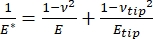
تجدر الإشارة إلى أنه نظرا لأن العديد من المواد (خاصة الأنسجة البيولوجية) هي في الواقع لزجة مرنة ، في الواقع ، يتكون المعامل (الديناميكي أو المعقد) من مكونات مرنة (تخزين ، في الطور) ولزجة (خسارة ، خارج الطور). في الممارسة الفعلية ، ما يتم قياسه في تجربة المسافة البادئة النانوية هو المعامل المختزل ، E * ، المرتبط بمعامل العينة الحقيقي محل الاهتمام ، E ، كما هو موضح في المعادلة (2):

Equation 2(2)

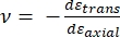
حيث Etip و ν tip هما معامل المرونة ونسبة بواسون ، على التوالي ، لطرف nanoindenter ، و ν هي نسبة بواسون المقدرة للعينة. نسبة بواسون هي النسبة السالبة للإجهاد المستعرض إلى المحوري ، وبالتالي تشير إلى درجة الاستطالة المستعرضة للعينة عند تعرضها لإجهاد محوري (على سبيل المثال ، أثناء تحميل المسافة البادئة النانوية) ، كما هو موضح في المعادلة (3):

Equation 3(3)

التحويل من المعامل المختزل إلى المعامل الفعلي ضروري لأن أ) قد يتم تحويل بعض الإجهاد المحوري الذي ينقله طرف المسافة البادئة إلى إجهاد عرضي (أي أن العينة قد تتشوه عن طريق التمدد أو الانكماش عموديا على اتجاه التحميل) ، و ب) الطرف البادئ ليس صعبا بشكل لا نهائي ، وبالتالي فإن فعل المسافة البادئة للعينة يؤدي إلى بعض (صغير) تشوه الطرف. لاحظ أنه في الحالة التي يكون فيهاطرف E >> E (أي أن طرف المسافة البادئة أصعب بكثير من العينة ، وهو ما يكون صحيحا غالبا عند استخدام مسبار الماس) ، فإن العلاقة بين معامل العينة المختزلة والفعلية تبسط إلى حد كبير إلى E ≈ E * (1 – v2). في حين أن المسافة البادئة النانوية الآلية متفوقة من حيث توصيف القوة الدقيق والنطاق الديناميكي ، فإن المسافة البادئة النانوية القائمة على الكابولي AFM أسرع ، وتوفر أوامر من حيث الحجم قوة أكبر وحساسية إزاحة ، وتمكن من تصوير عالي الدقة وتحسين تحديد موقع المسافة البادئة ، ويمكنها في نفس الوقت التحقيق في الخصائص المغناطيسية والكهربائية النانوية9. على وجه الخصوص ، تعتبر المسافة البادئة النانوية القائمة على الكابولي AFM متفوقة في القياس الكمي للخصائص الميكانيكية على المستوى النانوي للمواد اللينة (على سبيل المثال ، البوليمرات ، والمواد الهلامية ، والطبقات الثنائية الدهنية ، والخلايا أو المواد البيولوجية الأخرى) ، والأغشية الرقيقة للغاية (دون ميكرومتر) (حيث يمكن أن تلعب تأثيرات الركيزة دورا اعتمادا على عمق المسافة البادئة)10،11 ، والمواد المعلقة ثنائية الأبعاد (2D)12،13،14 مثل الجرافين 15،16 ، الميكا17 ، نيتريد البورون السداسي (h-BN) 18 ، أو ديكالكوجينيدات المعادن الانتقالية (TMDCs ؛ على سبيل المثال ، MoS2) 19. ويرجع ذلك إلى قوتها الرائعة (sub-nN) وحساسية الإزاحة (sub-nm) ، وهو أمر مهم لتحديد نقطة الاتصال الأولية بدقة والبقاء داخل منطقة التشوه المرن.

في المسافة البادئة النانوية القائمة على الكابولي AFM ، يتم تشغيل إزاحة مسبار AFM نحو سطح العينة بواسطة عنصر كهرضغطية معاير (الشكل 1 ب) ، مع انحناء الكابولي المرن في النهاية بسبب قوة المقاومة التي يتعرض لها عند ملامسته لسطح العينة. عادة ما يتم مراقبة هذا الانحناء أو الانحراف للناتئ عن طريق عكس الليزر من الجزء الخلفي من الكابولي إلى كاشف ضوئي (كاشف حساس للموضع [PSD]). إلى جانب معرفة صلابة الكابولي (في nN / nm) وحساسية الانحراف (في nm / V) ، من الممكن تحويل هذا الانحراف الكابولي المقاس (في V) إلى القوة (في nN) المطبقة على العينة. بعد الاتصال ، ينتج عن الفرق بين حركة Z-piezo وانحراف الكابولي عمق المسافة البادئة للعينة. إلى جانب معرفة وظيفة منطقة الطرف ، يتيح ذلك حساب منطقة تلامس عينة الطرف. يمكن بعد ذلك ملاءمة ميل الأجزاء الملامسة لمنحنيات مسافة القوة أو إزاحة القوة (F-D) الناتجة باستخدام نموذج ميكانيكا اتصال مناسب (انظر قسم تحليل البيانات في المناقشة) لتحديد الخواص النانوية الميكانيكية للعينة. في حين أن المسافة البادئة النانوية القائمة على الكابولي AFM تمتلك بعض المزايا المميزة على المسافة البادئة النانوية الآلية كما هو موضح أعلاه ، فإنها تقدم أيضا العديد من تحديات التنفيذ العملي ، مثل المعايرة وتآكل الأطراف وتحليل البيانات ، والتي سيتم مناقشتها هنا. الجانب السلبي المحتمل الآخر للمسافة البادئة النانوية القائمة على الكابولي AFM هو افتراض المرونة الخطية ، حيث يجب أن يكون نصف قطر التلامس وأعماق المسافة البادئة أصغر بكثير من نصف قطر المسافة البادئة ، والذي قد يكون من الصعب تحقيقه عند العمل مع مجسات AFM النانوية و / أو العينات التي تظهر خشونة سطح كبيرة.

تقليديا ، اقتصرت المسافة البادئة النانوية على المواقع الفردية أو تجارب المسافة البادئة للشبكة الصغيرة ، حيث يتم تحديد الموقع المطلوب (أي منطقة الاهتمام [ROI]) ويتم إجراء مسافة بادئة واحدة خاضعة للرقابة ، ومسافات بادئة متعددة في موقع واحد مفصولة ببعض وقت الانتظار ، و / أو شبكة خشنة من المسافات البادئة بمعدل هرتز. ومع ذلك ، فإن التطورات الحديثة في AFM تسمح بالحصول على الخواص الميكانيكية والطوبوغرافيا في وقت واحد من خلال استخدام أوضاع التصوير القائمة على منحنى القوة عالية السرعة (المشار إليها بأسماء تجارية مختلفة اعتمادا على الشركة المصنعة للنظام) ، حيث يتم إجراء منحنيات القوة بمعدل kHz تحت التحكم في الحمل ، مع استخدام أقصى قوة لعينة الطرف كنقطة ضبط للتصوير. كما تم تطوير طرق التأشير والتصوير ، مما يسمح بالحصول على صورة تضاريس AFM متبوعة بمسافة بادئة نانوية انتقائية لاحقة في نقاط الاهتمام داخل الصورة ، مما يوفر تحكما مكانيا نانويا على موقع المسافة البادئة النانوية. على الرغم من أنه ليس التركيز الأساسي لهذا العمل ، إلا أن أمثلة تطبيقية مختارة محددة لكل من التصوير القائم على منحنى القوة والمسافة البادئة النانوية القائمة على النقطة والتصوير الكابولي معروضة في النتائج التمثيلية ، ويمكن استخدامها جنبا إلى جنب مع البروتوكول الموضح أدناه إذا كان متاحا على منصة AFM المحددة المستخدمة. على وجه التحديد ، يحدد هذا العمل بروتوكولا معمما للتنفيذ العملي للمسافة البادئة النانوية القائمة على الكابولي AFM على أي نظام AFM قادر ويقدم أربعة أمثلة لحالة الاستخدام (اثنان في الهواء ، واثنان في السوائل) للتقنية ، بما في ذلك النتائج التمثيلية ومناقشة متعمقة للفروق الدقيقة والتحديات والاعتبارات المهمة لاستخدام التقنية بنجاح.

Protocol

ملاحظة: نظرا للتنوع الكبير في AFMs المتاحة تجاريا وتنوع أنواع العينات والتطبيقات الموجودة للمسافة البادئة النانوية القائمة على الكابولي ، فإن البروتوكول التالي مصمم عن قصد ليكون عاما نسبيا بطبيعته ، مع التركيز على الخطوات المشتركة اللازمة لجميع تجارب المسافة البادئة النانوية القائمة على…

Representative Results

منحنيات إزاحة القوةيوضح الشكل 7 منحنيات F-D التمثيلية شبه المثالية التي تم الحصول عليها من تجارب المسافة البادئة النانوية التي أجريت في الهواء على عينات صنوبر لوبلولي المضمنة بالراتنج (الشكل 7A) وفي السائل (محلول ملحي مخزن بالفوسفات [PBS]) على نوى الخلايا الجذعية ال…

Discussion

إعداد العينة
بالنسبة للمسافة البادئة النانوية في الهواء ، تشمل طرق التحضير الشائعة التقسيم بالتبريد (على سبيل المثال ، عينات الأنسجة) ، والطحن و / أو التلميع متبوعا بالموجات الدقيقة الفائقة (على سبيل المثال ، العينات البيولوجية المضمنة بالراتنج) ، أو الطحن الأيوني أو تحضير الحز…

Divulgations

The authors have nothing to disclose.

Acknowledgements

تم إجراء جميع تجارب AFM في مختبر علوم السطح بجامعة ولاية بويز (SSL). تم إجراء توصيف SEM في مركز ولاية بويز لتوصيف المواد (BSCMC). تم دعم الأبحاث الواردة في هذا المنشور فيما يتعلق بالمواد الأولية للوقود الحيوي جزئيا من قبل وزارة الطاقة الأمريكية ، ومكتب كفاءة الطاقة والطاقة المتجددة ، ومكتب تقنيات الطاقة الحيوية كجزء من اتحاد واجهة تحويل المواد الخام (FCIC) ، وبموجب عقد مكتب عمليات وزارة الطاقة في أيداهو DE-AC07-051ID14517. تم دعم دراسات ميكانيكا الخلية من قبل المعاهد الوطنية للصحة (الولايات المتحدة الأمريكية) بموجب منح AG059923 و AR075803 و P20GM109095 ، ومن قبل مؤسسة العلوم الوطنية (الولايات المتحدة الأمريكية) منح 1929188 و 2025505. تم دعم عمل أنظمة الطبقة الثنائية الدهنية النموذجية من قبل المعاهد الوطنية للصحة (الولايات المتحدة الأمريكية) بموجب منحة R01 EY030067. يشكر المؤلفون الدكتور إلتون جراوجنارد على إنتاج الصورة المركبة الموضحة في الشكل 11.

Materials

Atomic force microscope Bruker Dimension Icon Uses Nanoscope control software, including PeakForce Quantitative Nanomechanical Mapping (PF-QNM), FastForce Volume (FFV), and Point-and-Shoot Ramping experimental workspaces
AtomicJ American Institute of Physics https://doi.org/10.1063/1.4881683 Flexible, powerful, free open source Java-based force curve analysis software package. Supports numerous contact mechanic models, such as Hertz, Sneddon DMT, JKR, Maugis, and cone or pyramid (including blunt and truncated). Also includes a variety of initial contact point estimation methods to choose from. Supports batch processing of data and subsequent statistical analysis (e.g., averages, standard deviations, histograms, goodness of fit, etc.). Literature citation is: P. Hermanowicz, M. Sarna, K. Burda, and H. GabryEquation 1, “AtomicJ: An open source software for analysis of force curves” Rev. Sci. Instrum. 85: 063703 (2014), https://doi.org/10.1063/1.4881683
Buffer solution (PBS) Fisher Chemical (NaCl), Sigma Aldrich (KCl), Fisher BioReagents (Na2HPO4 and KH2PO4) S271 (>99% purity NaCl), P9541 (>99% purity KCl), BP332(>99% purity Na2HPO4), BP362 (>99% purity KH2PO4) Phosphate buffered saline (PBS) was prepared in the laboratory as an aqueous solution consisting of 137 mM NaCl, 2.7 mM KCl, 10 mM Na2HPO4, and 1.8 mM KH2PO4 dissolved in ultrapure water. Reagents were measured out using an analytical balance, and glassware was cleaned with soap and water followed by autoclaving immediately prior to use.
Chloroform
Diamond tip AFM probe Bruker PDNISP Pre-mounted factory-calibrated cube corner diamond (E = 1140 GPa) tip AFM probe (nominal R = 40 nm) with a stainless steel cantilever (nominal k = 225 N/m, f0 = 50 kHz). Spring constant is measured at the factory (k = 256 N/m for the probe, Serial #13435414, used here) and calibration data (including AFM images of indents showing probe geometry) is provided with the probe.
Diamond ultramicrotome blade Diatome Ultra 35° 2.1 mm width. Also used a standard glass blade for intial rough cut of sample surface before transitioning to diamond blade for final surface preparation
Epoxy Gorilla Glue 26853-31-6 Epoxy resin and hardner were mixed in a 1:1 ratio, a small drop was placed on a stainless steel sample puck (Ted Pella), and V1 grade muscovite mica (Ted Pella) was attached to create an atomically flat surface for preparation of phospholipid membranes.
Ethanol
LR white resin, medium grade (catalyzed) Electron Microscopy Sciences 14381 500 mL bottle, Lot #150629
Mesenchymal stem cells (MSCs) N/A N/A MSCs for nanomechanical studies were primary cells harvested from 8-10 week old male C57BL/6 mice as described in Goelzer, M. et al. "Lamin A/C Is Dispensable to Mechanical Repression of Adipogenesis" Int J Mol Sci 22: 6580 (2021) doi:10.3390/ijms22126580 and Peister, A. et al. "Adult stem cells from bone marrow (MSCs) isolated from different strains of inbred mice vary in surface epitopes, rates of proliferation, and differentiation potential" Blood 103: 1662-1668 (2004), doi:10.1182/blood-2003-09-3070.
Modulus standards Bruker PFQNM-SMPKIT-12M Used HOPG (E = 18 GPa) and PS (E = 2.7 GPa). Also contains 2x PDMS (Tack 0, E = 2.5 MPa; Tack 4, E = 3.5 MPa), PS-LDPE (E = 2.0/0.2 GPa), fused silica (E = 72.9 GPa), sapphire (E – 345 GPa), and tip characterization (titanium roughness) sample. All samples come pre-mounted on a 12 mm diameter steel disc (sample puck).
Muscovite mica Ted Pella 50-12 12 mm diameter, V1 grade muscovite mica
Nanscope Analysis Bruker Version 2.0 Free AFM image processing and analysis software package, but designed for, and proprietary/limited to Bruker AFMs; similar functionality is available from free, platform-independent AFM image processing and analysis software packages such as Gwyddion, WSxM, and others. Has built-in capabilities for force curve analysis, but AtomicJ is more flexible/full featured (e.g., more built-in contact mechanics models to choose from, statistical analysis of force curve fitting results, etc.) for force curve analysis and handles batch processing of force curves.
Phospholipids: POPC, Cholesterol (ovine) Avanti Polar Lipids POPC: CAS # 26853-31-6, Cholesterol: CAS # 57-88-5 POPC lipid dissolved in chloroform (25 mg/mL) was obtained from vendor and used without further purification. Cholesterol powder from the same vendor was dissolved in chloroform (20 mg/mL). 
Probe holder (fluid, lipid bilayers) Bruker MTFML-V2 Specific to the particular AFM used; MTFML-V2 is a glass probe holder for scanning in fluid on a MultiMode AFM.
Probe holder (fluid, MSCs) Bruker FastScan Bio Z-scanner Used with Dimension FastScan head (XY flexure scanners). Serial number MXYPOM5-1B154.
Probe holder (standard, ambient) Bruker DAFMCH Specific to the particular AFM used; DAFMCH is the standard contact and tapping mode probe holder for the Dimension Icon AFM, suitable for nanoindentation (PF-QNM, FFV, and point-and-shoot ramping)
Sample Puck Ted Pella 16218 Product number is for 15 mm diameter stainless steel sample puck. Also available in 6 mm, 10 mm, 12 mm, and 20 mm diameters at https://www.tedpella.com/AFM_html/AFM.aspx#anchor842459
Sapphire substrate Bruker PFQNM-SMPKIT-12M Extremely hard surface (E = 345 GPa) for measuring deflection sensitivity of probes (want all of the deflection to come from the probe, not the substrate). Part of the PF-QNM/modulus standards kit.
Scanning electron microscope Hitachi S-3400N-II Located at Boise State. Used to perform co-localized SEM/EDS on all samples except additively manufactured (AM) Ti-6Al-4V.
Silicon AFM probes (standard) NuNano Scout 350 Standard tapping mode silicon probe with reflective aluminum backside coating; k = 42 N/m (nominal), f0 = 350 kHz. Nominal R = 5 nm. Also available uncoated or with reflective gold backside coating. Probes with similar specifications are available from other manufacturers (e.g., Bruker TESPA-V2).
Silicon AFM probes (stiff) Bruker RTESPA-525, RTESPA-525-30  Rotated tip etched silicon probes with reflective aluminum backside coating; k = 200 N/m (nominal), f0 = 525 kHz. Nominal R = 8 nm for RTESPA-525, R = 30 nm for RTESPA-525-30. Spring constant of each RTESPA-525-30 is measured individually at the factory via laser Doppler vibrometry and supplied with the probe.
Silicon carbide grit paper (abrasive discs) Allied 50-10005 120 grit
Silicon nitride AFM probes (soft, large radius hemispherical tip) Bruker MLCT-SPH-5UM, MLCT-SPH-5UM-DC Also MLCT-SPH-1UM-DC. New product line of factory-calibrated (probe radius and spring constants of all cantilevers) large radius (R = 1 or 5 mm) hemispherical tip (at the end of a 23 mm long cylindrical shaft) probes. DC = drift compensation coating. 6 cantilevers/probe (A-F). Nominal spring constants: A, k = 0.07 N/m; B, k = 0.02 N/m; C, k = 0.01 N/m; D, k = 0.03 N/m; E, k = 0.1 N/m; F, k = 0.6 N/m.
Silicon nitride AFM probes (soft, medium sharp tip) Bruker DNP 4 cantilevers/probe (A-d). Nominal spring constants: A, k = 0.35 N/m; B, k = 0.12 N/m; C, k = 0.24 N/m; D, k = 0.06 N/m. Nominal radii of curvature, R = 10 nm.
Silicon nitride AFM probes (soft, sharp tip) Bruker ScanAsyst-Air Nominal values: resonance frequency, f0 = 70 kHz; spring constant, k = 0.4 N/m; radius of curvature, R = 2 nm. Designed for force curve based AFM imaging.
Superglue Henkel Loctite 495 Cyanoacrylate based instant adhesive. Lots of roughly equivalent products are readily available.
Syringe pump New Era Pump Systems NE1000US One channel syringe pump system with infusion and withdrawal capacity
Tip characterization standard Bruker PFQNM-SMPKIT-12M Titanium (Ti) roughness standard. Part of the PF-QNM/modulus standards kit.
Ultrahigh purity nitrogen (UHP N2), 99.999% Norco SPG TUHPNI – T T size compressed gas cylinder of ultrahigh purity (99.999%) nitrogen for drying samples
Ultramicrotome Leica EM UC6 Equipped with a glass blade (standard, for intial sample preparation) and a diamond blade (for final preparation)
Ultrapure water Thermo Fisher Barnstead Nanopure Model 7146 Model has been discontinued, but equivalent products are available. Produces ≥18.2 MΩ*cm ultrapure water with 1-5 ppb TOC (total organic content), per inline UV monitoring. Includes 0.2 µm particulate filter, ion exchange columns, and UV oxidation chamber.
Variable Speed Grinder Buehler EcoMet 3000 Used with silicon carbide grit papers during hand polishing.
Vibration isolation table (active) Herzan TS-140 Used with Bruker MultiMode AFM. Sits on a TMC 65-531 vibration isolation table. Bruker Dimension Icon AFM utilizes strictly passive vibration isolation (comes from manufacturer with custom acoustic hood, air table, and granite slab).
Vibration isolation table (passive) TMC 65-531 35" x 30" vibration isolation table with optional air damping (disabled). Used with Bruker MultiMode AFM. Herzan TS-140 "Table Stable" active vibration control table is located on top.

References

  1. Hart, E. W. Theory of the tensile test. Acta Metallurgica. 15 (2), 351-355 (1967).
  2. Fell, J. T., Newton, J. M. Determination of tablet strength by the diametral-compression test. Journal of Pharmaceutical Sciences. 59 (5), 688-691 (1970).
  3. Babiak, M., Gaff, M., Sikora, A., Hysek, &. #. 3. 5. 2. ;. Modulus of elasticity in three- and four-point bending of wood. Composite Structures. 204, 454-465 (2018).
  4. Song, S., Yovanovich, M. M. Relative contact pressure-Dependence on surface roughness and Vickers microhardness. Journal of Thermophysics and Heat Transfer. 2 (1), 43-47 (1988).
  5. Hays, C., Kendall, E. G. An analysis of Knoop microhardness. Metallography. 6 (4), 275-282 (1973).
  6. Hill, R., Storåkers, B., Zdunek, A. B. A theoretical study of the Brinell hardness test. Proceedings of the Royal Society of London. A. Mathematical and Physical Sciences. 423 (1865), 301-330 (1989).
  7. Oliver, W. C., Pharr, G. M. An improved technique for determining hardness and elastic modulus using load and displacement sensing indentation experiments. Journal of Materials Research. 7 (6), 1564-1583 (1992).
  8. Sakharova, N. A., Fernandes, J. V., Antunes, J. M., Oliveira, M. C. Comparison between Berkovich, Vickers and conical indentation tests: A three-dimensional numerical simulation study. International Journal of Solids and Structures. 46 (5), 1095-1104 (2009).
  9. Cohen, S. R., Kalfon-Cohen, E. Dynamic nanoindentation by instrumented nanoindentation and force microscopy: a comparative review. Beilstein Journal of Nanotechnology. 4 (1), 815-833 (2013).
  10. Saha, R., Nix, W. D. Effects of the substrate on the determination of thin film mechanical properties by nanoindentation. Acta Materialia. 50 (1), 23-38 (2002).
  11. Tsui, T. Y., Pharr, G. M. Substrate effects on nanoindentation mechanical property measurement of soft films on hard substrates. Journal of Materials Research. 14 (1), 292-301 (1999).
  12. Cao, G., Gao, H. Mechanical properties characterization of two-dimensional materials via nanoindentation experiments. Progress in Materials Science. 103, 558-595 (2019).
  13. Castellanos-Gomez, A., Singh, V., vander Zant, H. S. J., Steele, G. A. Mechanics of freely-suspended ultrathin layered materials. Annalen der Physik. 527 (1-2), 27-44 (2015).
  14. Cao, C., Sun, Y., Filleter, T. Characterizing mechanical behavior of atomically thin films: A review. Journal of Materials Research. 29 (3), 338-347 (2014).
  15. Lee, C., Wei, X., Kysar, J. W., Hone, J. Measurement of the elastic properties and intrinsic strength of monolayer graphene. Science. 321 (5887), 385-388 (2008).
  16. Elibol, K., et al. Visualising the strain distribution in suspended two-dimensional materials under local deformation. Scientific Reports. 6 (1), 28485 (2016).
  17. Castellanos-Gomez, A., et al. Mechanical properties of freely suspended atomically thin dielectric layers of mica. Nano Research. 5 (8), 550-557 (2012).
  18. Song, L., et al. Large scale growth and characterization of atomic hexagonal boron nitride layers. Nano Letters. 10 (8), 3209-3215 (2010).
  19. Castellanos-Gomez, A., et al. Elastic properties of freely suspended MoS2 nanosheets. Advanced Materials. 24 (6), 772-775 (2012).
  20. D’Costa, N. P., Hoh, J. H. Calibration of optical lever sensitivity for atomic force microscopy. Review of Scientific Instruments. 66 (10), 5096-5097 (1995).
  21. Wu, Y., et al. Evaluation of elastic modulus and hardness of crop stalks cell walls by nano-indentation. Bioresource Technology. 101 (8), 2867-2871 (2010).
  22. Barns, S., et al. Investigation of red blood cell mechanical properties using AFM indentation and coarse-grained particle method. BioMedical Engineering OnLine. 16 (1), 140 (2017).
  23. Hermanowicz, P., Sarna, M., Burda, K., Gabryś, H. AtomicJ: An open source software for analysis of force curves. Review of Scientific Instruments. 85 (6), 063703 (2014).
  24. Broitman, E. Indentation hardness measurements at macro-, micro-, and nanoscale: a critical overview. Tribology Letters. 65 (1), 23 (2016).
  25. Tiwari, A. . Nanomechanical Analysis of High Performance Materials. , (2015).
  26. Aggarwal, R. L., Ramdas, A. K. . Physical Properties of Diamond and Sapphire. , (2019).
  27. Boyd, E. J., Uttamchandani, D. Measurement of the anisotropy of Young’s modulus in single-crystal silicon. Journal of Microelectromechanical Systems. 21 (1), 243-249 (2012).
  28. Harding, J. W., Sneddon, I. N. The elastic stresses produced by the indentation of the plane surface of a semi-infinite elastic solid by a rigid punch. Mathematical Proceedings of the Cambridge Philosophical Society. 41 (1), 16-26 (2008).
  29. Lin, D. C., Dimitriadis, E. K., Horkay, F. Robust strategies for automated AFM force curve analysis-I. Non-adhesive indentation of soft, inhomogeneous materials. Journal of Biomechanical Engineering. 129 (3), 430-440 (2006).
  30. Lin, D. C., Dimitriadis, E. K., Horkay, F. Robust strategies for automated AFM force curve analysis-II: Adhesion-influenced indentation of soft, elastic materials. Journal of Biomechanical Engineering. 129 (6), 904-912 (2007).
  31. Haile, S., Palmer, M., Otey, A. Potential of loblolly pine: switchgrass alley cropping for provision of biofuel feedstock. Agroforestry Systems. 90 (5), 763-771 (2016).
  32. Lu, X., et al. Biomass logistics analysis for large scale biofuel production: Case study of loblolly pine and switchgrass. Bioresource Technology. 183, 1-9 (2015).
  33. Susaeta, A., Lal, P., Alavalapati, J., Mercer, E., Carter, D. Economics of intercropping loblolly pine and switchgrass for bioenergy markets in the southeastern United States. Agroforestry Systems. 86 (2), 287-298 (2012).
  34. Garcia, R. Nanomechanical mapping of soft materials with the atomic force microscope: methods, theory and applications. Chemical Society Reviews. 49 (16), 5850-5884 (2020).
  35. Derjaguin, B. V., Muller, V. M., Toporov, Y. P. Effect of contact deformations on the adhesion of particles. Journal of Colloid and Interface Science. 53 (2), 314-326 (1975).
  36. Ciesielski, P. N., et al. Engineering plant cell walls: tuning lignin monomer composition for deconstructable biofuel feedstocks or resilient biomaterials. Green Chemistry. 16 (5), 2627-2635 (2014).
  37. Liu, K., Ostadhassan, M., Zhou, J., Gentzis, T., Rezaee, R. Nanoscale pore structure characterization of the Bakken shale in the USA. Fuel. 209, 567-578 (2017).
  38. Maryon, O. O., et al. Co-localizing Kelvin probe force microscopy with other microscopies and spectroscopies: selected applications in corrosion characterization of alloys. JoVE. (184), e64102 (2022).
  39. Eliyahu, M., Emmanuel, S., Day-Stirrat, R. J., Macaulay, C. I. Mechanical properties of organic matter in shales mapped at the nanometer scale. Marine and Petroleum Geology. 59, 294-304 (2015).
  40. Li, C., et al. Nanomechanical characterization of organic matter in the Bakken formation by microscopy-based method. Marine and Petroleum Geology. 96, 128-138 (2018).
  41. Bouzid, T., et al. The LINC complex, mechanotransduction, and mesenchymal stem cell function and fate. Journal of Biological Engineering. 13 (1), 68 (2019).
  42. Dupont, S., et al. Role of YAP/TAZ in mechanotransduction. Nature. 474 (7350), 179-183 (2011).
  43. Wang, S., et al. CCM3 is a gatekeeper in focal adhesions regulating mechanotransduction and YAP/TAZ signalling. Nature Cell Biology. 23 (7), 758-770 (2021).
  44. Sen, B., et al. Mechanical strain inhibits adipogenesis in mesenchymal stem cells by stimulating a durable β-catenin signal. Endocrinology. 149 (12), 6065-6075 (2008).
  45. Sen, B., et al. mTORC2 regulates mechanically induced cytoskeletal reorganization and lineage selection in marrow-derived mesenchymal stem cells. Journal of Bone and Mineral Research. 29 (1), 78-89 (2014).
  46. Sen, B., et al. Mechanically induced nuclear shuttling of β-catenin requires co-transfer of actin. Stem Cells. 40 (4), 423-434 (2022).
  47. Newberg, J., et al. Isolated nuclei stiffen in response to low intensity vibration. Journal of Biomechanics. 111, 110012 (2020).
  48. Ding, Y., Xu, G. -. K., Wang, G. -. F. On the determination of elastic moduli of cells by AFM based indentation. Scientific Reports. 7 (1), 45575 (2017).
  49. Khadka, N. K., Timsina, R., Rowe, E., O’Dell, M., Mainali, L. Mechanical properties of the high cholesterol-containing membrane: An AFM study. Biochimica et Biophysica Acta. Biomembranes. 1863 (8), 183625 (2021).
  50. Castellana, E. T., Cremer, P. S. Solid supported lipid bilayers: From biophysical studies to sensor design. Surface Science Reports. 61 (10), 429-444 (2006).
  51. Qian, L., Zhao, H. Nanoindentation of soft biological materials. Micromachines. 9 (12), 654 (2018).
  52. Pittenger, B., Yablon, D. Improving the accuracy of nanomechanical measurements with force-curve-based AFM techniques. Bruker Application Notes. 149, (2017).
  53. Vorselen, D., Kooreman, E. S., Wuite, G. J. L., Roos, W. H. Controlled tip wear on high roughness surfaces yields gradual broadening and rounding of cantilever tips. Scientific Reports. 6 (1), 36972 (2016).
  54. Bhaskaran, H., et al. Ultralow nanoscale wear through atom-by-atom attrition in silicon-containing diamond-like carbon. Nature Nanotechnology. 5 (3), 181-185 (2010).
  55. Giannazzo, F., Schilirò, E., Greco, G., Roccaforte, F. Conductive atomic force microscopy of semiconducting transition metal dichalcogenides and heterostructures. Nanomaterials. 10 (4), 803 (2020).
  56. Melitz, W., Shen, J., Kummel, A. C., Lee, S. Kelvin probe force microscopy and its application. Surface Science Reports. 66 (1), 1-27 (2011).
  57. Kazakova, O., et al. Frontiers of magnetic force microscopy. Journal of Applied Physics. 125 (6), 060901 (2019).
  58. Kim, H. -. J., Yoo, S. -. S., Kim, D. -. E. Nano-scale wear: A review. International Journal of Precision Engineering and Manufacturing. 13 (9), 1709-1718 (2012).
  59. Heath, G. R., et al. Localization atomic force microscopy. Nature. 594 (7863), 385-390 (2021).
  60. Strahlendorff, T., Dai, G., Bergmann, D., Tutsch, R. Tip wear and tip breakage in high-speed atomic force microscopes. Ultramicroscopy. 201, 28-37 (2019).
  61. Lantz, M. A., et al. Wear-resistant nanoscale silicon carbide tips for scanning probe applications. Advanced Functional Materials. 22 (8), 1639-1645 (2012).
  62. Khurshudov, A. G., Kato, K., Koide, H. Wear of the AFM diamond tip sliding against silicon. Wear. 203, 22-27 (1997).
  63. Villarrubia, J. S. Algorithms for scanned probe microscope image simulation, surface reconstruction, and tip estimation. Journal of Research of the National Institute of Standards and Technology. 102 (4), 425 (1997).
  64. Kain, L., et al. Calibration of colloidal probes with atomic force microscopy for micromechanical assessment. Journal of the Mechanical Behavior of Biomedical Materials. 85, 225-236 (2018).
  65. Slattery, A. D., Blanch, A. J., Quinton, J. S., Gibson, C. T. Accurate measurement of Atomic Force Microscope cantilever deflection excluding tip-surface contact with application to force calibration. Ultramicroscopy. 131, 46-55 (2013).
  66. Dobrovinskaya, E. R., Lytvynov, L. A., Pishchik, V. . Sapphire: Material, Manufacturing, Applications. , (2009).
  67. te Riet, J., et al. Interlaboratory round robin on cantilever calibration for AFM force spectroscopy. Ultramicroscopy. 111 (12), 1659-1669 (2011).
  68. Pratt, J. R., Shaw, G. A., Kumanchik, L., Burnham, N. A. Quantitative assessment of sample stiffness and sliding friction from force curves in atomic force microscopy. Journal of Applied Physics. 107 (4), 044305 (2010).
  69. Slattery, A. D., Blanch, A. J., Quinton, J. S., Gibson, C. T. Calibration of atomic force microscope cantilevers using standard and inverted static methods assisted by FIB-milled spatial markers. Nanotechnology. 24 (1), 015710 (2012).
  70. Higgins, M. J., et al. Noninvasive determination of optical lever sensitivity in atomic force microscopy. Review of Scientific Instruments. 77 (1), 013701 (2006).
  71. Lévy, R., Maaloum, M. Measuring the spring constant of atomic force microscope cantilevers: thermal fluctuations and other methods. Nanotechnology. 13 (1), 33-37 (2001).
  72. Sikora, A. Quantitative normal force measurements by means of atomic force microscopy towards the accurate and easy spring constant determination. Nanoscience and Nanometrology. 2 (1), 8-29 (2016).
  73. Ohler, B. Cantilever spring constant calibration using laser Doppler vibrometry. Review of Scientific Instruments. 78 (6), 063701 (2007).
  74. Gates, R. S., Pratt, J. R. Accurate and precise calibration of AFM cantilever spring constants using laser Doppler vibrometry. Nanotechnology. 23 (37), 375702 (2012).
  75. Cleveland, J. P., Manne, S., Bocek, D., Hansma, P. K. A nondestructive method for determining the spring constant of cantilevers for scanning force microscopy. Review of Scientific Instruments. 64 (2), 403-405 (1993).
  76. Sader, J. E., Chon, J. W. M., Mulvaney, P. Calibration of rectangular atomic force microscope cantilevers. Review of Scientific Instruments. 70 (10), 3967-3969 (1999).
  77. Sader, J. E., et al. Spring constant calibration of atomic force microscope cantilevers of arbitrary shape. Review of Scientific Instruments. 83 (10), 103705 (2012).
  78. Sader, J. E. Frequency response of cantilever beams immersed in viscous fluids with applications to the atomic force microscope. Journal of Applied Physics. 84 (1), 64-76 (1998).
  79. Sader, J. E., Pacifico, J., Green, C. P., Mulvaney, P. General scaling law for stiffness measurement of small bodies with applications to the atomic force microscope. Journal of Applied Physics. 97 (12), 124903 (2005).
  80. Mendels, D. -. A., et al. Dynamic properties of AFM cantilevers and the calibration of their spring constants. Journal of Micromechanics and Microengineering. 16 (8), 1720-1733 (2006).
  81. Gao, S., Brand, U. In-situ nondestructive characterization of the normal spring constant of AFM cantilevers. Measurement Science and Technology. 25 (4), 044014 (2014).
  82. Gibson, C. T., Watson, G. S., Myhra, S. Determination of the spring constants of probes for force microscopy/spectroscopy. Nanotechnology. 7 (3), 259-262 (1996).
  83. Gates, R. S., Pratt, J. R. Prototype cantilevers for SI-traceable nanonewton force calibration. Measurement Science and Technology. 17 (10), 2852-2860 (2006).
  84. Neumeister, J. M., Ducker, W. A. Lateral, normal, and longitudinal spring constants of atomic force microscopy cantilevers. Review of Scientific Instruments. 65 (8), 2527-2531 (1994).
  85. Kim, M. S., Choi, I. M., Park, Y. K., Kang, D. I. Atomic force microscope probe calibration by use of a commercial precision balance. Measurement. 40 (7), 741-745 (2007).
  86. Kim, M. -. S., Choi, J. -. H., Park, Y. -. K., Kim, J. -. H. Atomic force microscope cantilever calibration device for quantified force metrology at micro- or nano-scale regime: the nano force calibrator (NFC). Metrologia. 43 (5), 389-395 (2006).
  87. Tian, Y., et al. A novel method and system for calibrating the spring constant of atomic force microscope cantilever based on electromagnetic actuation. Review of Scientific Instruments. 89 (12), 125119 (2018).
  88. Clifford, C. A., Seah, M. P. The determination of atomic force microscope cantilever spring constants via dimensional methods for nanomechanical analysis. Nanotechnology. 16 (9), 1666-1680 (2005).
  89. Chen, B. -. Y., Yeh, M. -. K., Tai, N. -. H. Accuracy of the spring constant of atomic force microscopy cantilevers by finite element method. Analytical Chemistry. 79 (4), 1333-1338 (2007).
  90. Mick, U., Eichhorn, V., Wortmann, T., Diederichs, C., Fatikow, S. Combined nanorobotic AFM/SEM system as novel toolbox for automated hybrid analysis and manipulation of nanoscale objects. 2010 IEEE International Conference on Robotics and Automation. , 4088-4093 (2010).
  91. Kim, M. -. S., Choi, J. -. H., Kim, J. -. H., Park, Y. -. K. Accurate determination of spring constant of atomic force microscope cantilevers and comparison with other methods. Measurement. 43 (4), 520 (2010).
  92. Zhang, G., Wei, Z., Ferrell, R. E. Elastic modulus and hardness of muscovite and rectorite determined by nanoindentation. Applied Clay Science. 43 (2), 271-281 (2009).
  93. Bobko, C. P., Ortega, J. A., Ulm, F. -. J. Comment on "Elastic modulus and hardness of muscovite and rectorite determined by nanoindentation by G. Zhang, Z. Wei and R.E. Ferrell. Applied Clay Science. 46 (4), 425-428 (2009).
  94. Zhang, G., Wei, Z., Ferrell, R. E. Reply to the Comment on "Elastic modulus and hardness of muscovite and rectorite determined by nanoindentation" by G. Zhang, Z. Wei and R. E. Ferrell. Applied Clay Science. 46 (4), 429-432 (2009).
  95. Jin, D. W., et al. Thermal stability and Young’s modulus of mechanically exfoliated flexible mica. Current Applied Physics. 18 (12), 1486-1491 (2018).
  96. Xiao, J., et al. Anisotropic friction behaviour of highly oriented pyrolytic graphite. Carbon. 65, 53-62 (2013).
  97. Hertz, H. Ueber die Berührung fester elastischer Körper. Journal für die reine und angewandte Mathematik. 1882 (92), 156-171 (1882).
  98. Johnson, K. L., Kendall, K., Roberts, A. D., Tabor, D. Surface energy and the contact of elastic solids. Proceedings of the Royal Society of London. A. Mathematical and Physical Sciences. 324 (1558), 301-313 (1971).
  99. Muller, V. M., Derjaguin, B. V., Toporov, Y. P. On two methods of calculation of the force of sticking of an elastic sphere to a rigid plane. Colloids and Surfaces. 7 (3), 251-259 (1983).
  100. Maugis, D. Adhesion of spheres: The JKR-DMT transition using a dugdale model. Journal of Colloid and Interface Science. 150 (1), 243-269 (1992).
  101. Muller, V. M., Yushchenko, V. S., Derjaguin, B. V. On the influence of molecular forces on the deformation of an elastic sphere and its sticking to a rigid plane. Journal of Colloid and Interface Science. 77 (1), 91-101 (1980).
  102. Muller, V. M., Yushchenko, V. S., Derjaguin, B. V. General theoretical consideration of the influence of surface forces on contact deformations and the reciprocal adhesion of elastic spherical particles. Journal of Colloid and Interface Science. 92 (1), 92-101 (1983).
  103. Johnson, K. L., Greenwood, J. A. An adhesion map for the contact of elastic spheres. Journal of Colloid and Interface Science. 192 (2), 326-333 (1997).
  104. Shi, X., Zhao, Y. -. P. Comparison of various adhesion contact theories and the influence of dimensionless load parameter. Journal of Adhesion Science and Technology. 18 (1), 55-68 (2004).
check_url/fr/64497?article_type=t

Play Video

Citer Cet Article
Enrriques, A. E., Howard, S., Timsina, R., Khadka, N. K., Hoover, A. N., Ray, A. E., Ding, L., Onwumelu, C., Nordeng, S., Mainali, L., Uzer, G., Davis, P. H. Atomic Force Microscopy Cantilever-Based Nanoindentation: Mechanical Property Measurements at the Nanoscale in Air and Fluid. J. Vis. Exp. (190), e64497, doi:10.3791/64497 (2022).

View Video