Summary

Rasterkraftmikroskopie Cantilever-basierte Nanoindentation: Messungen mechanischer Eigenschaften auf der Nanoskala in Luft und Flüssigkeit

Published: December 02, 2022
doi:

Summary

Die Quantifizierung der Kontaktfläche und der Kraft, die von einer Rasterkraftmikroskop-Sondenspitze (AFM) auf eine Probenoberfläche ausgeübt wird, ermöglicht die Bestimmung der mechanischen Eigenschaften im Nanobereich. Best Practices zur Implementierung von AFM-Cantilever-basierter Nanoindentation in Luft oder Flüssigkeit an weichen und harten Proben zur Messung des Elastizitätsmoduls oder anderer nanomechanischer Eigenschaften werden diskutiert.

Abstract

Ein Rasterkraftmikroskop (AFM) misst grundlegend die Wechselwirkung zwischen einer nanoskaligen AFM-Sondenspitze und der Probenoberfläche. Wenn die von der Sondenspitze ausgeübte Kraft und ihre Kontaktfläche mit der Probe quantifiziert werden können, ist es möglich, die nanoskaligen mechanischen Eigenschaften (z. B. Elastizität oder Elastizitätsmodul) der zu untersuchenden Oberfläche zu bestimmen. Ein detailliertes Verfahren zur Durchführung quantitativer AFM-Cantilever-basierter Nanoindentationsexperimente wird hier mit repräsentativen Beispielen vorgestellt, wie die Technik zur Bestimmung der Elastizitätsmodule einer Vielzahl von Probentypen, die von kPa bis GPa reichen, angewendet werden kann. Dazu gehören lebende mesenchymale Stammzellen (MSCs) und Zellkerne in physiologischem Puffer, in Harz eingebettete dehydrierte Loblolly-Kiefernquerschnitte und Bakken-Schiefer unterschiedlicher Zusammensetzung.

Darüber hinaus wird die AFM-Cantilever-basierte Nanoindentation verwendet, um die Bruchfestigkeit (d.h. Durchbruchkraft) von Phospholipid-Doppelschichten zu untersuchen. Wichtige praktische Überlegungen wie Methodenwahl und -entwicklung, Sondenauswahl und -kalibrierung, Identifizierung von Regionen von Interesse, Probenheterogenität, Strukturgröße und Aspektverhältnis, Spitzenverschleiß, Oberflächenrauheit sowie Datenanalyse und Messstatistik werden erörtert, um die ordnungsgemäße Implementierung der Technik zu unterstützen. Schließlich wird die Kolokalisierung von AFM-abgeleiteten nanomechanischen Karten mit elektronenmikroskopischen Techniken demonstriert, die zusätzliche Informationen über die Elementzusammensetzung liefern.

Introduction

Das Verständnis der mechanischen Eigenschaften von Werkstoffen ist eine der grundlegendsten und wesentlichsten Aufgaben im Ingenieurwesen. Für die Analyse von Schüttguteigenschaften stehen zahlreiche Methoden zur Charakterisierung der mechanischen Eigenschaften von Werkstoffsystemen zur Verfügung, darunter Zugversuche1, Druckversuche2 und Drei- oder Vierpunkt-Biegeversuche (Biegeversuche)3. Während diese mikroskaligen Tests unschätzbare Informationen über die Eigenschaften des Schüttguts liefern können, werden sie in der Regel bis zum Versagen durchgeführt und sind daher zerstörerisch. Darüber hinaus fehlt ihnen die räumliche Auflösung, die erforderlich ist, um die mikro- und nanoskaligen Eigenschaften vieler heute interessanter Materialsysteme wie dünner Schichten, biologischer Materialien und Nanokomposite genau zu untersuchen. Um einige der Probleme bei groß angelegten mechanischen Prüfungen, vor allem deren zerstörerische Natur, anzugehen, wurden Mikrohärteprüfungen aus der Mineralogie übernommen. Die Härte ist ein Maß für die Widerstandsfähigkeit eines Materials gegen plastische Verformung unter bestimmten Bedingungen. Im Allgemeinen wird bei Mikrohärteprüfungen eine steife Sonde, die normalerweise aus gehärtetem Stahl oder Diamant besteht, verwendet, um in ein Material einzudrücken. Die resultierende Eindringtiefe und/oder -fläche kann dann zur Bestimmung der Härte verwendet werden. Es wurden mehrere Methoden entwickelt, darunter die Härte Vickers4, Knoop5 und Brinell6 ; Jedes liefert ein Maß für die mikroskalige Materialhärte, jedoch unter unterschiedlichen Bedingungen und Definitionen, und liefert daher nur Daten, die mit Tests verglichen werden können, die unter denselben Bedingungen durchgeführt wurden.

Die instrumentierte Nanoindentation wurde entwickelt, um die relativen Werte zu verbessern, die mit den verschiedenen Mikrohärteprüfmethoden erhalten wurden, die räumliche Auflösung für die Analyse mechanischer Eigenschaften zu verbessern und die Analyse dünner Schichten zu ermöglichen. Wichtig ist, dass durch die Verwendung der zuerst von Oliver und Pharr7 entwickelten Methode der Elastizitäts- oder Elastizitätsmodul E eines Probenmaterials durch instrumentierte Nanoindentation bestimmt werden kann. Darüber hinaus kann durch den Einsatz einer dreiseitigen pyramidenförmigen Nanoeindringkörpersonde von Berkovich (deren ideale Spitzenflächenfunktion mit der der vierseitigen Pyramidensonde von Vickers übereinstimmt)8 ein direkter Vergleich zwischen nanoskaligen und traditionelleren mikroskaligen Härtemessungen durchgeführt werden. Mit der zunehmenden Popularität des AFM gewann auch die Cantilever-basierte Nanoindentation von AFM an Aufmerksamkeit, insbesondere für die Messung der mechanischen Eigenschaften weicherer Materialien. Wie in Abbildung 1 schematisch dargestellt, sind die beiden heute am häufigsten verwendeten Techniken zur Untersuchung und Quantifizierung nanoskaliger mechanischer Eigenschaften die instrumentierte Nanoindentation (Abbildung 1A) und die AFM-Cantilever-basierte Nanoindentation (Abbildung 1B)9, wobei letztere im Mittelpunkt dieser Arbeit steht.

Figure 1
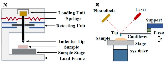
Abbildung 1: Vergleich von instrumentierten und AFM-Cantilever-basierten Nanoindentationssystemen. Schematische Diagramme, die typische Systeme für die Durchführung von (A) instrumentierter Nanoindentation und (B) AFM-Cantilever-basierter Nanoindentation darstellen. Diese Abbildung wurde von Qian et al.51 modifiziert. Abkürzung: AFM = Rasterkraftmikroskopie. Bitte klicken Sie hier, um eine größere Version dieser Abbildung zu sehen.

Sowohl instrumentierte als auch AFM-Cantilever-basierte Nanoindentation verwenden eine steife Sonde, um eine zu untersuchende Probenoberfläche zu verformen und die resultierende Kraft und Verschiebung in Abhängigkeit von der Zeit zu überwachen. Typischerweise wird entweder die gewünschte Last (d. h. Kraft) oder das (Z-Piezo-) Wegprofil vom Benutzer über die Softwareschnittstelle vorgegeben und direkt vom Gerät gesteuert, während der andere Parameter gemessen wird. Die mechanische Eigenschaft, die am häufigsten aus Nanoindentationsexperimenten gewonnen wird, ist der Elastizitätsmodul (E), auch als Elastizitätsmodul bezeichnet, der Druckeinheiten hat. Der Elastizitätsmodul eines Materials ist eine grundlegende Eigenschaft, die sich auf die Verbundsteifigkeit bezieht, und ist definiert als das Verhältnis von Zug- oder Druckspannung (σ, die aufgebrachte Kraft pro Flächeneinheit) zur axialen Dehnung (ε, die proportionale Verformung entlang der Eindringachse) während der elastischen (d. h. reversiblen oder vorübergehenden) Verformung vor dem Einsetzen der plastischen Verformung (Gleichung [1]):

Equation 1(1)

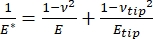
Es ist zu beachten, dass, da viele Materialien (insbesondere biologische Gewebe) tatsächlich viskoelastisch sind, der (dynamische oder komplexe) Modul in Wirklichkeit sowohl aus elastischen (Lagerung, in Phase) als auch aus viskosen (Verlust, phasenverschoben) Komponenten besteht. In der Praxis wird in einem Nanoindentationsexperiment der reduzierte Modul E * gemessen, der sich auf den wahren Probenmodul E bezieht, wie in Gleichung (2) gezeigt:

Equation 2(2)

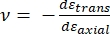
Dabei stehen E-Spitze und ν-Spitze für den Elastizitätsmodul bzw. das Poisson-Verhältnis der Nanoeindringkörperspitze und ν für das geschätzte Poisson-Verhältnis der Probe. Das Poisson-Verhältnis ist das negative Verhältnis der Quer- zur Axialdehnung und gibt somit den Grad der Querdehnung einer Probe an, wenn sie einer axialen Dehnung ausgesetzt wird (z. B. bei einer Nanoindentationsbelastung), wie in Gleichung (3) gezeigt:

Equation 3(3)

Die Umrechnung vom reduzierten in den tatsächlichen Modul ist notwendig, weil a) ein Teil der axialen Dehnung, die von der Eindringkörperspitze übertragen wird, in Querdehnung umgewandelt werden kann (d. h. die Probe kann sich durch Ausdehnung oder Kontraktion senkrecht zur Belastungsrichtung verformen) und b) die Eindringkörperspitze nicht unendlich hart ist und daher das Eindrücken der Probe zu einer (kleinen) Verformung der Spitze führt. Beachten Sie, dass in dem Fall, in dem die E-Spitze >> E ist (d. h. die Eindringkörperspitze viel härter ist als die Probe, was bei der Verwendung einer Diamantsonde oft der Fall ist), die Beziehung zwischen dem reduzierten und dem tatsächlichen Probenmodul stark zu E ≈ E*(1 – v2) vereinfacht wird. Während die instrumentierte Nanoindentation in Bezug auf die genaue Kraftcharakterisierung und den Dynamikbereich überlegen ist, ist die Cantilever-basierte Nanoindentation auf AFM-Basis schneller, bietet eine um Größenordnungen höhere Kraft- und Wegempfindlichkeit, ermöglicht eine Bildgebung mit höherer Auflösung und eine verbesserte Lokalisierung von Eindrücken und kann gleichzeitig magnetische und elektrische Eigenschaften im Nanomaßstab untersuchen9. Insbesondere die freitragende Nanoindentation auf AFM-Basis eignet sich hervorragend für die Quantifizierung mechanischer Eigenschaften auf der Nanoskala von weichen Materialien (z. B. Polymere, Gele, Lipiddoppelschichten und Zellen oder andere biologische Materialien), extrem dünnen (Sub-μm) Filmen (bei denen Substrateffekte je nach Eindringtiefe ins Spiel kommen können)10,11 und suspendierten zweidimensionalen (2D) Materialien12,13,14 wie Graphen 15,16, Glimmer17, hexagonales Bornitrid (h-BN)18 oder Übergangsmetalldichalkogenide (TMDCs; z. B. MoS2)19. Dies ist auf seine hervorragende Kraft- (sub-nN) und Verschiebungsempfindlichkeit (sub-nm) zurückzuführen, die wichtig ist, um den anfänglichen Kontaktpunkt genau zu bestimmen und innerhalb des elastischen Verformungsbereichs zu bleiben.

Bei der Cantilever-basierten AFM-Nanoindentation wird die Verschiebung einer AFM-Sonde in Richtung der Probenoberfläche durch ein kalibriertes piezoelektrisches Element (Abbildung 1B) betätigt, wobei sich der flexible Cantilever aufgrund der Widerstandskraft, die beim Kontakt mit der Probenoberfläche auftritt, schließlich biegt. Diese Biegung oder Auslenkung des Auslegers wird in der Regel überwacht, indem ein Laser von der Rückseite des Auslegers in einen Photodetektor (positionsempfindlicher Detektor [PSD]) reflektiert wird. Gepaart mit der Kenntnis der Cantilever-Steifigkeit (in nN/nm) und der Durchbiegungsempfindlichkeit (in nm/V) ist es möglich, diese gemessene Cantilever-Auslenkung (in V) in die auf die Probe ausgeübte Kraft (in nN) umzurechnen. Nach dem Kontakt ergibt die Differenz zwischen der Z-Piezobewegung und der Cantilever-Auslenkung die Eindringtiefe der Probe. In Kombination mit der Kenntnis der Spitzenflächenfunktion ermöglicht dies die Berechnung der Spitzen-Probe-Kontaktfläche. Die Steigung der in Kontakt befindlichen Teile der resultierenden Kraft-Weg- oder Kraft-Weg-Kurven (F-D) kann dann mit einem geeigneten Kontaktmechanikmodell (siehe Abschnitt “ Datenanalyse” der Diskussion) angepasst werden, um die nanomechanischen Eigenschaften der Probe zu bestimmen. Während die freitragende Nanoindentation auf AFM-Basis einige deutliche Vorteile gegenüber der oben beschriebenen instrumentierten Nanoindentation aufweist, bringt sie auch einige praktische Herausforderungen bei der Implementierung mit sich, wie z. B. Kalibrierung, Spitzenverschleiß und Datenanalyse, die hier diskutiert werden. Ein weiterer potenzieller Nachteil der freitragenden Nanoindentation auf AFM-Basis ist die Annahme einer linearen Elastizität, da der Kontaktradius und die Eindringtiefe viel kleiner sein müssen als der Eindringkörperradius, was bei der Arbeit mit nanoskaligen AFM-Sonden und/oder Proben mit signifikanter Oberflächenrauheit schwierig zu erreichen sein kann.

Traditionell wurde die Nanoindentation auf einzelne Stellen oder kleine Gittereindruckexperimente beschränkt, bei denen eine gewünschte Position (d. h. Region of Interest [ROI]) ausgewählt wird und ein einzelner kontrollierter Eindruck, mehrere Eindrücke an einer einzigen Stelle, die durch eine gewisse Wartezeit getrennt sind, und/oder ein grobes Raster von Einrückungen mit einer Rate in der Größenordnung von Hz durchgeführt werden. Jüngste Fortschritte im AFM ermöglichen jedoch die gleichzeitige Erfassung mechanischer Eigenschaften und Topografie durch die Verwendung von Hochgeschwindigkeits-Kraftkurven-basierten Bildgebungsmodi (je nach Systemhersteller unter verschiedenen Handelsnamen bezeichnet), bei denen Kraftkurven mit einer kHz-Rate unter Lastkontrolle durchgeführt werden, wobei die maximale Kraft zwischen Spitze und Probe als Bildgebungssollwert verwendet wird. Es wurden auch Point-and-Shoot-Methoden entwickelt, die die Aufnahme eines AFM-Topographiebildes mit anschließender selektiver Nanoindentation an interessanten Punkten innerhalb des Bildes ermöglichen, was eine nanoskalige räumliche Kontrolle über die Position der Nanoindentation ermöglicht. Obwohl dies nicht der Hauptfokus dieser Arbeit ist, werden in den repräsentativen Ergebnissen spezifische ausgewählte Anwendungsbeispiele sowohl der kraftkurvenbasierten Bildgebung als auch der Point-and-Shoot-Cantilever-basierten Nanoindentation vorgestellt, die in Verbindung mit dem unten beschriebenen Protokoll verwendet werden können, sofern dies auf der jeweils verwendeten AFM-Plattform verfügbar ist. Konkret skizziert diese Arbeit ein verallgemeinertes Protokoll für die praktische Implementierung der AFM-Cantilever-basierten Nanoindentation auf jedem leistungsfähigen AFM-System und bietet vier Anwendungsfallbeispiele (zwei in Luft, zwei in Flüssigkeit) der Technik, einschließlich repräsentativer Ergebnisse und einer eingehenden Diskussion der Nuancen, Herausforderungen und wichtigen Überlegungen für den erfolgreichen Einsatz der Technik.

Protocol

HINWEIS: Aufgrund der großen Vielfalt an kommerziell erhältlichen AFMs und der Vielfalt der Probentypen und Anwendungen, die es für die Cantilever-basierte Nanoindentation gibt, ist das folgende Protokoll absichtlich relativ allgemein gehalten und konzentriert sich auf die gemeinsamen Schritte, die für alle Cantilever-basierten Nanoindentationsexperimente unabhängig von Gerät oder Hersteller erforderlich sind. Aus diesem Grund gehen die Autoren davon aus, dass der Leser zumindest über eine grundlegende Vertrauthei…

Representative Results

Kraft-Weg-KurvenAbbildung 7 zeigt repräsentative, nahezu ideale F-D-Kurven, die aus Nanoindentationsexperimenten gewonnen wurden, die in Luft an in Harz eingebetteten Loblolly-Kiefernproben (Abbildung 7A) und in Flüssigkeit (phosphatgepufferte Kochsalzlösung [PBS]) an mesenchymalen Stammzellkernen (MSC) (Abbildung 7B) durchgeführt wurden. Die Verwendung eines beliebigen kontaktmechanischen Modells beruht auf…

Discussion

Probenvorbereitung
Zu den gängigen Präparationsmethoden für die Nanoindentation in Luft gehören Kryoschnitt (z. B. Gewebeproben), Schleifen und/oder Polieren mit anschließendem Ultramikrotomieren (z. B. in Harz eingebettete biologische Proben), Ionenmahlen oder fokussierte Ionenstrahlpräparation (z. B. Halbleiter-, poröse oder gemischte Härteproben, die nicht poliert werden können), mechanisches oder elektrochemisches Polieren (z. B. Metalllegierungen) oder Dünnschichtabscheidung (z. B. Atom…

Divulgations

The authors have nothing to disclose.

Acknowledgements

Alle AFM-Experimente wurden im Surface Science Laboratory (SSL) der Boise State University durchgeführt. Die REM-Charakterisierung wurde im Boise State Center for Materials Characterization (BSCMC) durchgeführt. Die in dieser Veröffentlichung berichteten Forschungsarbeiten zu Biokraftstoffrohstoffen wurden teilweise vom US-Energieministerium, Office of Energy Efficiency and Renewable Energy, Bioenergy Technologies Office im Rahmen des Feedstock Conversion Interface Consortium (FCIC) und im Rahmen des DOE Idaho Operations Office-Vertrags DE-AC07-051ID14517 unterstützt. Die Studien zur Zellmechanik wurden von den National Institutes of Health (USA) im Rahmen von Zuschüssen AG059923, AR075803 und P20GM109095 sowie von Zuschüssen der National Science Foundation (USA) 1929188 und 2025505 unterstützt. Die Arbeit an Modelllipid-Doppelschichtsystemen wurde von den National Institutes of Health (USA) im Rahmen des Stipendiums R01 EY030067 unterstützt. Die Autoren danken Dr. Elton Graugnard für die Erstellung des in Abbildung 11 gezeigten zusammengesetzten Bildes.

Materials

Atomic force microscope Bruker Dimension Icon Uses Nanoscope control software, including PeakForce Quantitative Nanomechanical Mapping (PF-QNM), FastForce Volume (FFV), and Point-and-Shoot Ramping experimental workspaces
AtomicJ American Institute of Physics https://doi.org/10.1063/1.4881683 Flexible, powerful, free open source Java-based force curve analysis software package. Supports numerous contact mechanic models, such as Hertz, Sneddon DMT, JKR, Maugis, and cone or pyramid (including blunt and truncated). Also includes a variety of initial contact point estimation methods to choose from. Supports batch processing of data and subsequent statistical analysis (e.g., averages, standard deviations, histograms, goodness of fit, etc.). Literature citation is: P. Hermanowicz, M. Sarna, K. Burda, and H. GabryEquation 1, “AtomicJ: An open source software for analysis of force curves” Rev. Sci. Instrum. 85: 063703 (2014), https://doi.org/10.1063/1.4881683
Buffer solution (PBS) Fisher Chemical (NaCl), Sigma Aldrich (KCl), Fisher BioReagents (Na2HPO4 and KH2PO4) S271 (>99% purity NaCl), P9541 (>99% purity KCl), BP332(>99% purity Na2HPO4), BP362 (>99% purity KH2PO4) Phosphate buffered saline (PBS) was prepared in the laboratory as an aqueous solution consisting of 137 mM NaCl, 2.7 mM KCl, 10 mM Na2HPO4, and 1.8 mM KH2PO4 dissolved in ultrapure water. Reagents were measured out using an analytical balance, and glassware was cleaned with soap and water followed by autoclaving immediately prior to use.
Chloroform
Diamond tip AFM probe Bruker PDNISP Pre-mounted factory-calibrated cube corner diamond (E = 1140 GPa) tip AFM probe (nominal R = 40 nm) with a stainless steel cantilever (nominal k = 225 N/m, f0 = 50 kHz). Spring constant is measured at the factory (k = 256 N/m for the probe, Serial #13435414, used here) and calibration data (including AFM images of indents showing probe geometry) is provided with the probe.
Diamond ultramicrotome blade Diatome Ultra 35° 2.1 mm width. Also used a standard glass blade for intial rough cut of sample surface before transitioning to diamond blade for final surface preparation
Epoxy Gorilla Glue 26853-31-6 Epoxy resin and hardner were mixed in a 1:1 ratio, a small drop was placed on a stainless steel sample puck (Ted Pella), and V1 grade muscovite mica (Ted Pella) was attached to create an atomically flat surface for preparation of phospholipid membranes.
Ethanol
LR white resin, medium grade (catalyzed) Electron Microscopy Sciences 14381 500 mL bottle, Lot #150629
Mesenchymal stem cells (MSCs) N/A N/A MSCs for nanomechanical studies were primary cells harvested from 8-10 week old male C57BL/6 mice as described in Goelzer, M. et al. "Lamin A/C Is Dispensable to Mechanical Repression of Adipogenesis" Int J Mol Sci 22: 6580 (2021) doi:10.3390/ijms22126580 and Peister, A. et al. "Adult stem cells from bone marrow (MSCs) isolated from different strains of inbred mice vary in surface epitopes, rates of proliferation, and differentiation potential" Blood 103: 1662-1668 (2004), doi:10.1182/blood-2003-09-3070.
Modulus standards Bruker PFQNM-SMPKIT-12M Used HOPG (E = 18 GPa) and PS (E = 2.7 GPa). Also contains 2x PDMS (Tack 0, E = 2.5 MPa; Tack 4, E = 3.5 MPa), PS-LDPE (E = 2.0/0.2 GPa), fused silica (E = 72.9 GPa), sapphire (E – 345 GPa), and tip characterization (titanium roughness) sample. All samples come pre-mounted on a 12 mm diameter steel disc (sample puck).
Muscovite mica Ted Pella 50-12 12 mm diameter, V1 grade muscovite mica
Nanscope Analysis Bruker Version 2.0 Free AFM image processing and analysis software package, but designed for, and proprietary/limited to Bruker AFMs; similar functionality is available from free, platform-independent AFM image processing and analysis software packages such as Gwyddion, WSxM, and others. Has built-in capabilities for force curve analysis, but AtomicJ is more flexible/full featured (e.g., more built-in contact mechanics models to choose from, statistical analysis of force curve fitting results, etc.) for force curve analysis and handles batch processing of force curves.
Phospholipids: POPC, Cholesterol (ovine) Avanti Polar Lipids POPC: CAS # 26853-31-6, Cholesterol: CAS # 57-88-5 POPC lipid dissolved in chloroform (25 mg/mL) was obtained from vendor and used without further purification. Cholesterol powder from the same vendor was dissolved in chloroform (20 mg/mL). 
Probe holder (fluid, lipid bilayers) Bruker MTFML-V2 Specific to the particular AFM used; MTFML-V2 is a glass probe holder for scanning in fluid on a MultiMode AFM.
Probe holder (fluid, MSCs) Bruker FastScan Bio Z-scanner Used with Dimension FastScan head (XY flexure scanners). Serial number MXYPOM5-1B154.
Probe holder (standard, ambient) Bruker DAFMCH Specific to the particular AFM used; DAFMCH is the standard contact and tapping mode probe holder for the Dimension Icon AFM, suitable for nanoindentation (PF-QNM, FFV, and point-and-shoot ramping)
Sample Puck Ted Pella 16218 Product number is for 15 mm diameter stainless steel sample puck. Also available in 6 mm, 10 mm, 12 mm, and 20 mm diameters at https://www.tedpella.com/AFM_html/AFM.aspx#anchor842459
Sapphire substrate Bruker PFQNM-SMPKIT-12M Extremely hard surface (E = 345 GPa) for measuring deflection sensitivity of probes (want all of the deflection to come from the probe, not the substrate). Part of the PF-QNM/modulus standards kit.
Scanning electron microscope Hitachi S-3400N-II Located at Boise State. Used to perform co-localized SEM/EDS on all samples except additively manufactured (AM) Ti-6Al-4V.
Silicon AFM probes (standard) NuNano Scout 350 Standard tapping mode silicon probe with reflective aluminum backside coating; k = 42 N/m (nominal), f0 = 350 kHz. Nominal R = 5 nm. Also available uncoated or with reflective gold backside coating. Probes with similar specifications are available from other manufacturers (e.g., Bruker TESPA-V2).
Silicon AFM probes (stiff) Bruker RTESPA-525, RTESPA-525-30  Rotated tip etched silicon probes with reflective aluminum backside coating; k = 200 N/m (nominal), f0 = 525 kHz. Nominal R = 8 nm for RTESPA-525, R = 30 nm for RTESPA-525-30. Spring constant of each RTESPA-525-30 is measured individually at the factory via laser Doppler vibrometry and supplied with the probe.
Silicon carbide grit paper (abrasive discs) Allied 50-10005 120 grit
Silicon nitride AFM probes (soft, large radius hemispherical tip) Bruker MLCT-SPH-5UM, MLCT-SPH-5UM-DC Also MLCT-SPH-1UM-DC. New product line of factory-calibrated (probe radius and spring constants of all cantilevers) large radius (R = 1 or 5 mm) hemispherical tip (at the end of a 23 mm long cylindrical shaft) probes. DC = drift compensation coating. 6 cantilevers/probe (A-F). Nominal spring constants: A, k = 0.07 N/m; B, k = 0.02 N/m; C, k = 0.01 N/m; D, k = 0.03 N/m; E, k = 0.1 N/m; F, k = 0.6 N/m.
Silicon nitride AFM probes (soft, medium sharp tip) Bruker DNP 4 cantilevers/probe (A-d). Nominal spring constants: A, k = 0.35 N/m; B, k = 0.12 N/m; C, k = 0.24 N/m; D, k = 0.06 N/m. Nominal radii of curvature, R = 10 nm.
Silicon nitride AFM probes (soft, sharp tip) Bruker ScanAsyst-Air Nominal values: resonance frequency, f0 = 70 kHz; spring constant, k = 0.4 N/m; radius of curvature, R = 2 nm. Designed for force curve based AFM imaging.
Superglue Henkel Loctite 495 Cyanoacrylate based instant adhesive. Lots of roughly equivalent products are readily available.
Syringe pump New Era Pump Systems NE1000US One channel syringe pump system with infusion and withdrawal capacity
Tip characterization standard Bruker PFQNM-SMPKIT-12M Titanium (Ti) roughness standard. Part of the PF-QNM/modulus standards kit.
Ultrahigh purity nitrogen (UHP N2), 99.999% Norco SPG TUHPNI – T T size compressed gas cylinder of ultrahigh purity (99.999%) nitrogen for drying samples
Ultramicrotome Leica EM UC6 Equipped with a glass blade (standard, for intial sample preparation) and a diamond blade (for final preparation)
Ultrapure water Thermo Fisher Barnstead Nanopure Model 7146 Model has been discontinued, but equivalent products are available. Produces ≥18.2 MΩ*cm ultrapure water with 1-5 ppb TOC (total organic content), per inline UV monitoring. Includes 0.2 µm particulate filter, ion exchange columns, and UV oxidation chamber.
Variable Speed Grinder Buehler EcoMet 3000 Used with silicon carbide grit papers during hand polishing.
Vibration isolation table (active) Herzan TS-140 Used with Bruker MultiMode AFM. Sits on a TMC 65-531 vibration isolation table. Bruker Dimension Icon AFM utilizes strictly passive vibration isolation (comes from manufacturer with custom acoustic hood, air table, and granite slab).
Vibration isolation table (passive) TMC 65-531 35" x 30" vibration isolation table with optional air damping (disabled). Used with Bruker MultiMode AFM. Herzan TS-140 "Table Stable" active vibration control table is located on top.

References

  1. Hart, E. W. Theory of the tensile test. Acta Metallurgica. 15 (2), 351-355 (1967).
  2. Fell, J. T., Newton, J. M. Determination of tablet strength by the diametral-compression test. Journal of Pharmaceutical Sciences. 59 (5), 688-691 (1970).
  3. Babiak, M., Gaff, M., Sikora, A., Hysek, &. #. 3. 5. 2. ;. Modulus of elasticity in three- and four-point bending of wood. Composite Structures. 204, 454-465 (2018).
  4. Song, S., Yovanovich, M. M. Relative contact pressure-Dependence on surface roughness and Vickers microhardness. Journal of Thermophysics and Heat Transfer. 2 (1), 43-47 (1988).
  5. Hays, C., Kendall, E. G. An analysis of Knoop microhardness. Metallography. 6 (4), 275-282 (1973).
  6. Hill, R., Storåkers, B., Zdunek, A. B. A theoretical study of the Brinell hardness test. Proceedings of the Royal Society of London. A. Mathematical and Physical Sciences. 423 (1865), 301-330 (1989).
  7. Oliver, W. C., Pharr, G. M. An improved technique for determining hardness and elastic modulus using load and displacement sensing indentation experiments. Journal of Materials Research. 7 (6), 1564-1583 (1992).
  8. Sakharova, N. A., Fernandes, J. V., Antunes, J. M., Oliveira, M. C. Comparison between Berkovich, Vickers and conical indentation tests: A three-dimensional numerical simulation study. International Journal of Solids and Structures. 46 (5), 1095-1104 (2009).
  9. Cohen, S. R., Kalfon-Cohen, E. Dynamic nanoindentation by instrumented nanoindentation and force microscopy: a comparative review. Beilstein Journal of Nanotechnology. 4 (1), 815-833 (2013).
  10. Saha, R., Nix, W. D. Effects of the substrate on the determination of thin film mechanical properties by nanoindentation. Acta Materialia. 50 (1), 23-38 (2002).
  11. Tsui, T. Y., Pharr, G. M. Substrate effects on nanoindentation mechanical property measurement of soft films on hard substrates. Journal of Materials Research. 14 (1), 292-301 (1999).
  12. Cao, G., Gao, H. Mechanical properties characterization of two-dimensional materials via nanoindentation experiments. Progress in Materials Science. 103, 558-595 (2019).
  13. Castellanos-Gomez, A., Singh, V., vander Zant, H. S. J., Steele, G. A. Mechanics of freely-suspended ultrathin layered materials. Annalen der Physik. 527 (1-2), 27-44 (2015).
  14. Cao, C., Sun, Y., Filleter, T. Characterizing mechanical behavior of atomically thin films: A review. Journal of Materials Research. 29 (3), 338-347 (2014).
  15. Lee, C., Wei, X., Kysar, J. W., Hone, J. Measurement of the elastic properties and intrinsic strength of monolayer graphene. Science. 321 (5887), 385-388 (2008).
  16. Elibol, K., et al. Visualising the strain distribution in suspended two-dimensional materials under local deformation. Scientific Reports. 6 (1), 28485 (2016).
  17. Castellanos-Gomez, A., et al. Mechanical properties of freely suspended atomically thin dielectric layers of mica. Nano Research. 5 (8), 550-557 (2012).
  18. Song, L., et al. Large scale growth and characterization of atomic hexagonal boron nitride layers. Nano Letters. 10 (8), 3209-3215 (2010).
  19. Castellanos-Gomez, A., et al. Elastic properties of freely suspended MoS2 nanosheets. Advanced Materials. 24 (6), 772-775 (2012).
  20. D’Costa, N. P., Hoh, J. H. Calibration of optical lever sensitivity for atomic force microscopy. Review of Scientific Instruments. 66 (10), 5096-5097 (1995).
  21. Wu, Y., et al. Evaluation of elastic modulus and hardness of crop stalks cell walls by nano-indentation. Bioresource Technology. 101 (8), 2867-2871 (2010).
  22. Barns, S., et al. Investigation of red blood cell mechanical properties using AFM indentation and coarse-grained particle method. BioMedical Engineering OnLine. 16 (1), 140 (2017).
  23. Hermanowicz, P., Sarna, M., Burda, K., Gabryś, H. AtomicJ: An open source software for analysis of force curves. Review of Scientific Instruments. 85 (6), 063703 (2014).
  24. Broitman, E. Indentation hardness measurements at macro-, micro-, and nanoscale: a critical overview. Tribology Letters. 65 (1), 23 (2016).
  25. Tiwari, A. . Nanomechanical Analysis of High Performance Materials. , (2015).
  26. Aggarwal, R. L., Ramdas, A. K. . Physical Properties of Diamond and Sapphire. , (2019).
  27. Boyd, E. J., Uttamchandani, D. Measurement of the anisotropy of Young’s modulus in single-crystal silicon. Journal of Microelectromechanical Systems. 21 (1), 243-249 (2012).
  28. Harding, J. W., Sneddon, I. N. The elastic stresses produced by the indentation of the plane surface of a semi-infinite elastic solid by a rigid punch. Mathematical Proceedings of the Cambridge Philosophical Society. 41 (1), 16-26 (2008).
  29. Lin, D. C., Dimitriadis, E. K., Horkay, F. Robust strategies for automated AFM force curve analysis-I. Non-adhesive indentation of soft, inhomogeneous materials. Journal of Biomechanical Engineering. 129 (3), 430-440 (2006).
  30. Lin, D. C., Dimitriadis, E. K., Horkay, F. Robust strategies for automated AFM force curve analysis-II: Adhesion-influenced indentation of soft, elastic materials. Journal of Biomechanical Engineering. 129 (6), 904-912 (2007).
  31. Haile, S., Palmer, M., Otey, A. Potential of loblolly pine: switchgrass alley cropping for provision of biofuel feedstock. Agroforestry Systems. 90 (5), 763-771 (2016).
  32. Lu, X., et al. Biomass logistics analysis for large scale biofuel production: Case study of loblolly pine and switchgrass. Bioresource Technology. 183, 1-9 (2015).
  33. Susaeta, A., Lal, P., Alavalapati, J., Mercer, E., Carter, D. Economics of intercropping loblolly pine and switchgrass for bioenergy markets in the southeastern United States. Agroforestry Systems. 86 (2), 287-298 (2012).
  34. Garcia, R. Nanomechanical mapping of soft materials with the atomic force microscope: methods, theory and applications. Chemical Society Reviews. 49 (16), 5850-5884 (2020).
  35. Derjaguin, B. V., Muller, V. M., Toporov, Y. P. Effect of contact deformations on the adhesion of particles. Journal of Colloid and Interface Science. 53 (2), 314-326 (1975).
  36. Ciesielski, P. N., et al. Engineering plant cell walls: tuning lignin monomer composition for deconstructable biofuel feedstocks or resilient biomaterials. Green Chemistry. 16 (5), 2627-2635 (2014).
  37. Liu, K., Ostadhassan, M., Zhou, J., Gentzis, T., Rezaee, R. Nanoscale pore structure characterization of the Bakken shale in the USA. Fuel. 209, 567-578 (2017).
  38. Maryon, O. O., et al. Co-localizing Kelvin probe force microscopy with other microscopies and spectroscopies: selected applications in corrosion characterization of alloys. JoVE. (184), e64102 (2022).
  39. Eliyahu, M., Emmanuel, S., Day-Stirrat, R. J., Macaulay, C. I. Mechanical properties of organic matter in shales mapped at the nanometer scale. Marine and Petroleum Geology. 59, 294-304 (2015).
  40. Li, C., et al. Nanomechanical characterization of organic matter in the Bakken formation by microscopy-based method. Marine and Petroleum Geology. 96, 128-138 (2018).
  41. Bouzid, T., et al. The LINC complex, mechanotransduction, and mesenchymal stem cell function and fate. Journal of Biological Engineering. 13 (1), 68 (2019).
  42. Dupont, S., et al. Role of YAP/TAZ in mechanotransduction. Nature. 474 (7350), 179-183 (2011).
  43. Wang, S., et al. CCM3 is a gatekeeper in focal adhesions regulating mechanotransduction and YAP/TAZ signalling. Nature Cell Biology. 23 (7), 758-770 (2021).
  44. Sen, B., et al. Mechanical strain inhibits adipogenesis in mesenchymal stem cells by stimulating a durable β-catenin signal. Endocrinology. 149 (12), 6065-6075 (2008).
  45. Sen, B., et al. mTORC2 regulates mechanically induced cytoskeletal reorganization and lineage selection in marrow-derived mesenchymal stem cells. Journal of Bone and Mineral Research. 29 (1), 78-89 (2014).
  46. Sen, B., et al. Mechanically induced nuclear shuttling of β-catenin requires co-transfer of actin. Stem Cells. 40 (4), 423-434 (2022).
  47. Newberg, J., et al. Isolated nuclei stiffen in response to low intensity vibration. Journal of Biomechanics. 111, 110012 (2020).
  48. Ding, Y., Xu, G. -. K., Wang, G. -. F. On the determination of elastic moduli of cells by AFM based indentation. Scientific Reports. 7 (1), 45575 (2017).
  49. Khadka, N. K., Timsina, R., Rowe, E., O’Dell, M., Mainali, L. Mechanical properties of the high cholesterol-containing membrane: An AFM study. Biochimica et Biophysica Acta. Biomembranes. 1863 (8), 183625 (2021).
  50. Castellana, E. T., Cremer, P. S. Solid supported lipid bilayers: From biophysical studies to sensor design. Surface Science Reports. 61 (10), 429-444 (2006).
  51. Qian, L., Zhao, H. Nanoindentation of soft biological materials. Micromachines. 9 (12), 654 (2018).
  52. Pittenger, B., Yablon, D. Improving the accuracy of nanomechanical measurements with force-curve-based AFM techniques. Bruker Application Notes. 149, (2017).
  53. Vorselen, D., Kooreman, E. S., Wuite, G. J. L., Roos, W. H. Controlled tip wear on high roughness surfaces yields gradual broadening and rounding of cantilever tips. Scientific Reports. 6 (1), 36972 (2016).
  54. Bhaskaran, H., et al. Ultralow nanoscale wear through atom-by-atom attrition in silicon-containing diamond-like carbon. Nature Nanotechnology. 5 (3), 181-185 (2010).
  55. Giannazzo, F., Schilirò, E., Greco, G., Roccaforte, F. Conductive atomic force microscopy of semiconducting transition metal dichalcogenides and heterostructures. Nanomaterials. 10 (4), 803 (2020).
  56. Melitz, W., Shen, J., Kummel, A. C., Lee, S. Kelvin probe force microscopy and its application. Surface Science Reports. 66 (1), 1-27 (2011).
  57. Kazakova, O., et al. Frontiers of magnetic force microscopy. Journal of Applied Physics. 125 (6), 060901 (2019).
  58. Kim, H. -. J., Yoo, S. -. S., Kim, D. -. E. Nano-scale wear: A review. International Journal of Precision Engineering and Manufacturing. 13 (9), 1709-1718 (2012).
  59. Heath, G. R., et al. Localization atomic force microscopy. Nature. 594 (7863), 385-390 (2021).
  60. Strahlendorff, T., Dai, G., Bergmann, D., Tutsch, R. Tip wear and tip breakage in high-speed atomic force microscopes. Ultramicroscopy. 201, 28-37 (2019).
  61. Lantz, M. A., et al. Wear-resistant nanoscale silicon carbide tips for scanning probe applications. Advanced Functional Materials. 22 (8), 1639-1645 (2012).
  62. Khurshudov, A. G., Kato, K., Koide, H. Wear of the AFM diamond tip sliding against silicon. Wear. 203, 22-27 (1997).
  63. Villarrubia, J. S. Algorithms for scanned probe microscope image simulation, surface reconstruction, and tip estimation. Journal of Research of the National Institute of Standards and Technology. 102 (4), 425 (1997).
  64. Kain, L., et al. Calibration of colloidal probes with atomic force microscopy for micromechanical assessment. Journal of the Mechanical Behavior of Biomedical Materials. 85, 225-236 (2018).
  65. Slattery, A. D., Blanch, A. J., Quinton, J. S., Gibson, C. T. Accurate measurement of Atomic Force Microscope cantilever deflection excluding tip-surface contact with application to force calibration. Ultramicroscopy. 131, 46-55 (2013).
  66. Dobrovinskaya, E. R., Lytvynov, L. A., Pishchik, V. . Sapphire: Material, Manufacturing, Applications. , (2009).
  67. te Riet, J., et al. Interlaboratory round robin on cantilever calibration for AFM force spectroscopy. Ultramicroscopy. 111 (12), 1659-1669 (2011).
  68. Pratt, J. R., Shaw, G. A., Kumanchik, L., Burnham, N. A. Quantitative assessment of sample stiffness and sliding friction from force curves in atomic force microscopy. Journal of Applied Physics. 107 (4), 044305 (2010).
  69. Slattery, A. D., Blanch, A. J., Quinton, J. S., Gibson, C. T. Calibration of atomic force microscope cantilevers using standard and inverted static methods assisted by FIB-milled spatial markers. Nanotechnology. 24 (1), 015710 (2012).
  70. Higgins, M. J., et al. Noninvasive determination of optical lever sensitivity in atomic force microscopy. Review of Scientific Instruments. 77 (1), 013701 (2006).
  71. Lévy, R., Maaloum, M. Measuring the spring constant of atomic force microscope cantilevers: thermal fluctuations and other methods. Nanotechnology. 13 (1), 33-37 (2001).
  72. Sikora, A. Quantitative normal force measurements by means of atomic force microscopy towards the accurate and easy spring constant determination. Nanoscience and Nanometrology. 2 (1), 8-29 (2016).
  73. Ohler, B. Cantilever spring constant calibration using laser Doppler vibrometry. Review of Scientific Instruments. 78 (6), 063701 (2007).
  74. Gates, R. S., Pratt, J. R. Accurate and precise calibration of AFM cantilever spring constants using laser Doppler vibrometry. Nanotechnology. 23 (37), 375702 (2012).
  75. Cleveland, J. P., Manne, S., Bocek, D., Hansma, P. K. A nondestructive method for determining the spring constant of cantilevers for scanning force microscopy. Review of Scientific Instruments. 64 (2), 403-405 (1993).
  76. Sader, J. E., Chon, J. W. M., Mulvaney, P. Calibration of rectangular atomic force microscope cantilevers. Review of Scientific Instruments. 70 (10), 3967-3969 (1999).
  77. Sader, J. E., et al. Spring constant calibration of atomic force microscope cantilevers of arbitrary shape. Review of Scientific Instruments. 83 (10), 103705 (2012).
  78. Sader, J. E. Frequency response of cantilever beams immersed in viscous fluids with applications to the atomic force microscope. Journal of Applied Physics. 84 (1), 64-76 (1998).
  79. Sader, J. E., Pacifico, J., Green, C. P., Mulvaney, P. General scaling law for stiffness measurement of small bodies with applications to the atomic force microscope. Journal of Applied Physics. 97 (12), 124903 (2005).
  80. Mendels, D. -. A., et al. Dynamic properties of AFM cantilevers and the calibration of their spring constants. Journal of Micromechanics and Microengineering. 16 (8), 1720-1733 (2006).
  81. Gao, S., Brand, U. In-situ nondestructive characterization of the normal spring constant of AFM cantilevers. Measurement Science and Technology. 25 (4), 044014 (2014).
  82. Gibson, C. T., Watson, G. S., Myhra, S. Determination of the spring constants of probes for force microscopy/spectroscopy. Nanotechnology. 7 (3), 259-262 (1996).
  83. Gates, R. S., Pratt, J. R. Prototype cantilevers for SI-traceable nanonewton force calibration. Measurement Science and Technology. 17 (10), 2852-2860 (2006).
  84. Neumeister, J. M., Ducker, W. A. Lateral, normal, and longitudinal spring constants of atomic force microscopy cantilevers. Review of Scientific Instruments. 65 (8), 2527-2531 (1994).
  85. Kim, M. S., Choi, I. M., Park, Y. K., Kang, D. I. Atomic force microscope probe calibration by use of a commercial precision balance. Measurement. 40 (7), 741-745 (2007).
  86. Kim, M. -. S., Choi, J. -. H., Park, Y. -. K., Kim, J. -. H. Atomic force microscope cantilever calibration device for quantified force metrology at micro- or nano-scale regime: the nano force calibrator (NFC). Metrologia. 43 (5), 389-395 (2006).
  87. Tian, Y., et al. A novel method and system for calibrating the spring constant of atomic force microscope cantilever based on electromagnetic actuation. Review of Scientific Instruments. 89 (12), 125119 (2018).
  88. Clifford, C. A., Seah, M. P. The determination of atomic force microscope cantilever spring constants via dimensional methods for nanomechanical analysis. Nanotechnology. 16 (9), 1666-1680 (2005).
  89. Chen, B. -. Y., Yeh, M. -. K., Tai, N. -. H. Accuracy of the spring constant of atomic force microscopy cantilevers by finite element method. Analytical Chemistry. 79 (4), 1333-1338 (2007).
  90. Mick, U., Eichhorn, V., Wortmann, T., Diederichs, C., Fatikow, S. Combined nanorobotic AFM/SEM system as novel toolbox for automated hybrid analysis and manipulation of nanoscale objects. 2010 IEEE International Conference on Robotics and Automation. , 4088-4093 (2010).
  91. Kim, M. -. S., Choi, J. -. H., Kim, J. -. H., Park, Y. -. K. Accurate determination of spring constant of atomic force microscope cantilevers and comparison with other methods. Measurement. 43 (4), 520 (2010).
  92. Zhang, G., Wei, Z., Ferrell, R. E. Elastic modulus and hardness of muscovite and rectorite determined by nanoindentation. Applied Clay Science. 43 (2), 271-281 (2009).
  93. Bobko, C. P., Ortega, J. A., Ulm, F. -. J. Comment on "Elastic modulus and hardness of muscovite and rectorite determined by nanoindentation by G. Zhang, Z. Wei and R.E. Ferrell. Applied Clay Science. 46 (4), 425-428 (2009).
  94. Zhang, G., Wei, Z., Ferrell, R. E. Reply to the Comment on "Elastic modulus and hardness of muscovite and rectorite determined by nanoindentation" by G. Zhang, Z. Wei and R. E. Ferrell. Applied Clay Science. 46 (4), 429-432 (2009).
  95. Jin, D. W., et al. Thermal stability and Young’s modulus of mechanically exfoliated flexible mica. Current Applied Physics. 18 (12), 1486-1491 (2018).
  96. Xiao, J., et al. Anisotropic friction behaviour of highly oriented pyrolytic graphite. Carbon. 65, 53-62 (2013).
  97. Hertz, H. Ueber die Berührung fester elastischer Körper. Journal für die reine und angewandte Mathematik. 1882 (92), 156-171 (1882).
  98. Johnson, K. L., Kendall, K., Roberts, A. D., Tabor, D. Surface energy and the contact of elastic solids. Proceedings of the Royal Society of London. A. Mathematical and Physical Sciences. 324 (1558), 301-313 (1971).
  99. Muller, V. M., Derjaguin, B. V., Toporov, Y. P. On two methods of calculation of the force of sticking of an elastic sphere to a rigid plane. Colloids and Surfaces. 7 (3), 251-259 (1983).
  100. Maugis, D. Adhesion of spheres: The JKR-DMT transition using a dugdale model. Journal of Colloid and Interface Science. 150 (1), 243-269 (1992).
  101. Muller, V. M., Yushchenko, V. S., Derjaguin, B. V. On the influence of molecular forces on the deformation of an elastic sphere and its sticking to a rigid plane. Journal of Colloid and Interface Science. 77 (1), 91-101 (1980).
  102. Muller, V. M., Yushchenko, V. S., Derjaguin, B. V. General theoretical consideration of the influence of surface forces on contact deformations and the reciprocal adhesion of elastic spherical particles. Journal of Colloid and Interface Science. 92 (1), 92-101 (1983).
  103. Johnson, K. L., Greenwood, J. A. An adhesion map for the contact of elastic spheres. Journal of Colloid and Interface Science. 192 (2), 326-333 (1997).
  104. Shi, X., Zhao, Y. -. P. Comparison of various adhesion contact theories and the influence of dimensionless load parameter. Journal of Adhesion Science and Technology. 18 (1), 55-68 (2004).
check_url/fr/64497?article_type=t

Play Video

Citer Cet Article
Enrriques, A. E., Howard, S., Timsina, R., Khadka, N. K., Hoover, A. N., Ray, A. E., Ding, L., Onwumelu, C., Nordeng, S., Mainali, L., Uzer, G., Davis, P. H. Atomic Force Microscopy Cantilever-Based Nanoindentation: Mechanical Property Measurements at the Nanoscale in Air and Fluid. J. Vis. Exp. (190), e64497, doi:10.3791/64497 (2022).

View Video