Assorbitore di gas
English
Diviser
Vue d'ensemble
Fonte: Michael G. Benton e Kerry M. Dooley,Dipartimento di Ingegneria Chimica, Louisiana State University, Baton Rouge, LA
Gli assorbitori di gas vengono utilizzati per rimuovere i contaminanti dai flussi di gas. Per raggiungere questo obiettivo vengono utilizzati più progetti1. Una colonna a letto imballata utilizza flussi di gas e liquidi che scorrono l’uno contro l’altro in una colonna imballata con materiali di imballaggio sfusi, come ceramica, metalli e plastica, o imballaggi strutturati1. Il letto imballato utilizza la superficie creata dall’imballaggio per creare una quantità massima di contatto efficiente tra le due fasi1. I sistemi sono a bassa manutenzione e possono gestire materiali corrosivi con elevate velocità di trasferimento di massa1. Le colonne di spruzzatura sono un altro tipo di assorbitore, che utilizza un contatto diretto costante tra le due fasi, con il gas che si muove verso l’alto e il liquido che viene spruzzato nel flusso di gas1. Questo sistema ha solo uno stadio e scarse velocità di trasferimento di massa, ma è molto efficace per i soluti con elevata solubilità liquida1.
L’obiettivo di questo esperimento è determinare in che modo le variabili tra cui la portata del gas, la portata d’acqua e la concentrazione di anidride carbonica influenzano il coefficiente di trasferimento di massa complessivo in un assorbitore di gas. Capire come questi parametri influenzano la rimozione di CO2 consente di ottimizzare la rimozione dei contaminanti. L’esperimento utilizza una colonna di assorbimento del gas controcorrodo dell’acqua imballata in modo casuale. Sono state utilizzate otto serie con due diverse portate di gas, portate liquide e concentrazioni di CO2. Durante ogni corsa, le pressioni parziali sono state prelevate dal basso, dal centro e dalla parte superiore dell’unità della colonna e sono state calcolate le pressioni parziali di equilibrio. Queste pressioni sono state poi utilizzate per trovare il coefficiente di trasferimento di massa e i coefficienti di trasferimento di massa sono stati confrontati con i valori teorici.
Principles
Procédure
Résultats
Partial pressures were taken from each trial run. Mass transfer coefficients were calculated from these and compared to predicted values (Figure 2). The predicted values arise from the calculated operating line for the absorber (see reference 2 for an in-depth discussion of the operating line). Solid lines represent the values calculated using the operating line, while triangles represent the experimental mass transfer coefficient values. Confidence intervals for the model values and the mean mass transfer coefficient were plotted with dashed lines. These values were compared to determine how the experimental parameters (liquid flow rate, gas flow rate, and CO2 partial pressure) affected the overall mass transfer coefficient. Under these operating conditions, only liquid flow rate had a statistically significant effect on mass transfer when compared to the confidence interval. The results showed that gas flow rate and feed composition had little to no effect on the mass transfer coefficient.
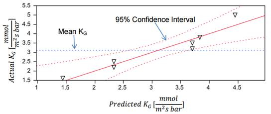
Figure 2: Model of the predicted and actual values of the mass transfer coefficient.
Theoretical KG values for a high (30 L/min) and low (20 L/min) were calculated from mass transfer coefficient correlations and are shown as blue and green lines, respectively, in Figure 3. The experimental KG values at a variety of liquid flow rates were plotted against the theoretical values and showed similar trends, verifying the dependence of KG on liquid flow rate. The theoretical values showed some variation from the experimental values, attributable to minor experimental error.
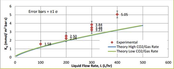
Figure 3: A graphical depiction of experimental value compared to theoretical values.
Applications and Summary
The goal of this experiment was to use factors of gas flow rate, water flow rate, and carbon dioxide concentration to determine the overall mass transfer coefficient in a gas absorber. The experiment used a randomly packed GUNT CE 400 water counter-flow gas absorption column. Eight runs with two different gas flow rates, liquid flow rates, and CO2 concentrations were performed. Partial pressures were taken from the bottom, middle, and top of the column unit, and these pressures were then used to find the mass transfer coefficient.
Under these operating conditions, only the liquid flow rate had a significant statistical effect on mass transfer when compared to the confidence interval for the given conditions. The process is liquid-phase mass transfer controlled. Gas-related factors such as CO2 concentration and gas flow rate will have little to no significance.
Gas absorption is an important mechanism for safety in the production of chlorine3. During normal operation, gas absorbers treat any consistently occurring leaks. The start-up of a chlorine operation must be treated until it produces a gas-free product. In the event of a breakdown in the process, absorbers must be used to treat the gas that has been produced. Additionally, when new leaks form, the main emergency response unit is the standby gas absorbers. Treatment units are vitally important in these operating conditions, as they help create a safe environment when dealing with a dangerous product3.
When refining natural gas, absorption towers are used to remove natural gas liquids from the gas phase4. An absorbing oil with an affinity to natural gas liquids removes the liquid from the gas phase, purifying the product. The oil with natural gas liquids is then further purified to recover the liquids, such as butane, pentanes and other molecules. The oil can then be used again for treatment.
Absorption is also used to remove the major impurities CO2 and H2S from wellhead natural gas, converting it to pipeline gas. The process uses aqueous amines or glycols as solvents at low temperatures (typically <40 °C)5.
References
- Absorbers – Separations: Chemical – MEL Equipment Encyclopedia 4.0. N.p., n.d. Web. 28 Jan. 2017.
- Welty, James R., Rorrer, Gregory L., and David G. Foster. Fundamentals of Momentum, Heat, and Mass Transfer. 6th ed. John Wiley & Sons, Inc., Hoboken, NJ, 2015
- Chloric Gas Absorption." GEA engineering for a better world. N.p., n.d. Web. 28 Jan. 2017.
- NaturalGas.org." NaturalGasorg. N.p., n.d. Web. 28 Jan. 2017.
- Fundamentals of Natural Gas Processing, A.J. Kidnay and W.R. Parrish, Taylor and Francis, Boca Raton, 2006.
Transcription
Gas absorbers are used to remove contaminants from gas streams, such as floo gas from an exhaust. A gas absorber uses a column often containing random or structured packing material. Packed bed absorbers utilize gas and liquid streams which flow counter current to each other. The contaminant gas is absorbed into the liquid stream, resulting in reduced contaminant in the exit gas. The absorption process depends heavily on the operating parameters, which must be studied in order to optimize the process. Here, we will investigate the absorption of carbon dioxide into water, and examine how the operating parameters affect the separation and efficiency of the system.
A gas absorption unit uses contact with a liquid solvent to remove the substance from a gas mixture. Mass is transferred from the gas mixture to the solvent, with the two phases near equilibrium. Then, the separation of the gas liquid phase occurs. The overall material balance for the absorber is shown here, where V and L are the vapor and liquid flow rates respectively, thus the component material balance for the absorbed component A incorporates the mole fraction of A in the vapor and liquid phase. The overall mass transfer coefficient is the rate at which the concentration of one species moves from one fluid to the other. Here, KG is the overall mass transfer coefficient, PAG is the partial pressure of the gas being absorbed, P star A is the equilibrium pressure from Henry’s Law, A is the mass transfer effective area, Z is the height of the packing, and GS is the gas molar flow rate per cross sectional of the column. Mass transfer depends on the mass transfer coefficients in each phase, and the amount of interphasial area available in the absorber. Henry’s Law and Raoult’s Law are applied to calculate the partial pressures in equilibrium with the liquid phase concentrations. In the following experiment, a packed column gas absorber will be used to absorb carbon dioxide from a gas stream into water. The gas and water streams enter the column from the bottom and top respectively, enabling counter flow. The carbon dioxide composition at the inlet is controlled using valves for carbon dioxide and air. Then the concentration of carbon dioxide in the outlet is measured. Now that we’ve discussed the basics of gas absorption, let’s take a look at how to run the apparatus in the lab.
The equipment used in this demonstration is a packed counterflow gas absorption column. The column is packed with 13 milliliter berl saddles at a bed depth of 34 centimeters. The valves at the entrance and exit of the column allow gas to escape, while an infrared spectrometer is used to measure the partial pressures of CO2 in the gas phase. To begin the experiment, switch on the master switch, then close the valve used to control the amount of water in the column. Open the airflow valve completely and open the adjusting valve for column pressure. Set the airflow rate to the desired level. Use a minimum of 30 liters per minute, then increase as desired. Set the column pressure to about 0.5 bar using the adjusting valve for pressure. Next, set the carbon dioxide flow rate starting at about four liters per minute, then set the water flow rate, also starting at about four liters per minute. Adjust the water flow throughout the experiment to maintain a constant water level in the tank. Sample and measure the carbon dioxide concentration as desired at the base, center, and head of the column using the in-line pressure gauges. Repeat the experiment by performing eight runs. Use two different gas flow rates, liquid flow rates, and carbon dioxide concentrations, thereby enabling the determination of the most important variables in the system. Be sure to allow the system to achieve steady state whenever a flow rate is altered.
Now that we have demonstrated how to perform the gas absorption, let’s take a look at the results. First, calculate partial pressures and equilibrium partial pressures for each run, then use the partial pressures to calculate the mass transfer coefficients. The calculated values are shown here as triangles, while the predicted values, shown as the solid line, arise from computing the operating and equilibrium lines. Confidence intervals for the model values and the mean mass transfer coefficient were plotted with dashed lines. There was no deviation between the predicted and actual values, showing that the column is at steady state with equilibrium at the interface between the liquid and gas phases. Now, let’s compare the mass transfer coefficients under the same operating conditions. The theoretical values, shown as the green and blue lines, showed similar trends to the experimental data. Whether the gas rate was high or low, the model and experiment behave the same, showing that the gas flow rate had little or no effect on the mass transfer coefficient in the ranges examined.
Finally, let’s take a look at some applications of this technology in industry. Packed bed absorbers are the most common piece of equipment used for air pollution control. In these cases, gas absorbers are often called scrubbers. Scrubbers are used to remove corrosive fumes such as sulfuric acid, nitric acid, and hydrochloric acid from industrial gasses and vents from chemical plants, oil refineries, and pulp and paper plants. The operation of removing the absorbed gas from the solvent is called stripping. Strippers are often used in conjunction with absorbers in order to recover the absorbed gas and recycle the liquid solvent. This is especially important when the waste water contains nitrogen and phosphorus components. This waste water used to be expelled directly into oceans, however this led to the excessive growth of algae, called eutrophication, which in turn severely damaged natural ecosystems. You’ve just watched Jove’s introduction to gas absorption.
You should now understand how a gas absorber removes an impurity from a gas stream, how to run a gas absorber in the lab, and how to analyze the data to understand the separation. Thanks for watching!