测试芬管热交换器的传热效率
English
Diviser
Vue d'ensemble
资料来源:迈克尔·本顿和克里·杜利,路易斯安那州立大学化学工程系,巴吞鲁日,洛杉矶
换热器将热量从一种流体传输到另一种流体。存在多类热交换器,以满足不同的需求。一些最常见的类型是壳和管交换器和板交换器1。外壳和管式换热器使用流体流1的管系统。一组管包含要冷却或加热的液体,而第二组包含的液体要么吸收热量,要么传输热量1。板式换热器使用类似的概念,其中板紧密地连接在一起,每个之间的小间隙,液体流动1。在板块之间流动的流体在热和冷之间交替,这样热量就会进入或流出必要的溪流1。这些交换器具有较大的表面面积,因此通常效率更高。
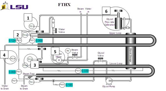
本实验的目的是测试翅管热交换器的传热效率(图1),并将其与无翅片的热交换器的理论效率进行比较。实验数据将测量单二醇(MEG)的三种不同流速。每个 MEG 流速将采用两种不同的水流量。使用威尔逊绘图方法,将从实验数据中确定传热系数。此外,Reynold 的数量和传输的热量将比较带和不使用散热片的流量,以评估传热效率。

图1:芬管换热器。1) MEG 出水温度 2) 进水温度 3) MEG 入口温度 4) 出水口温度 5) 水表 6) MEG 积累目视玻璃/气缸。
Principles
Procédure
Résultats
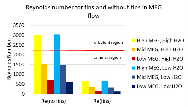
The finned tube heat exchanger did not reach turbulent flow (Figure 2). The fins provide additional surfaces on which boundary layers form, as known through laminar and turbulent flow theory. If the fluid is not at a sufficient velocity, the fluid will not reach turbulence. The boundary layers between the fins overlap in the laminar region, so the fluid will remain laminar.

Figure 2: Reynolds numbers for each setting.
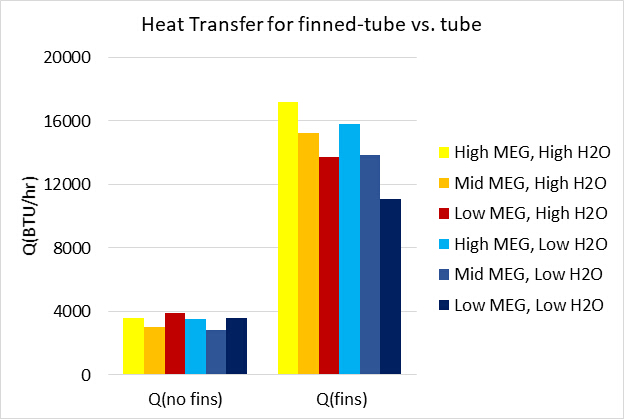
The amount of heat transferred, Q, in the tubes with and without fins at different flow rates of MEG was compared (Figure 3). The results show that a finned-tube transfers more heat than a tube without fins at the same operating conditions. In this experiment, the fins clearly improved heat transfer. This is because heat transfer is more effective when there is a greater surface area available. The finned-tube heat exchanger transferred more heat (Figure 3), despite the lower Reynolds number (Figure 2).

Figure 3: Heat transferred between exchangers with and without fins at each flow rate.
Applications and Summary
Heat exchangers are used in a variety of industries, including agriculture, chemical production, and HVAC. The goal for this experiment was to test the heat transfer efficiency of a finned-tube heat exchanger and compare it to the theoretical efficiency of a heat exchanger without fins. Experimental data was measured for three different flow rates of monoethylene glycol (MEG) and two unique water flow rates for each MEG flow rate used. The Reynold’s number was determined for flow with and without the fins and was used to calculate the heat transfer coefficient, surface area, and fin efficiency for each unique trial run. This data was used to evaluate if turbulent flow is possible without the fins and under which set of trial conditions the most heat transfer occurs. The finned tubes did not reach turbulent flow. The results showed that a fin tube will transfer more heat than a tube without fins at the same operating conditions because the flow of MEG through the heat exchanger will not reach turbulence.
In the agriculture industry, heat exchangers are used in the processing of sugar and ethanol2. Both of these products are processed into a juice, which must be heated to be further processed2. Heat exchangers are used in heating the juices for clarification2. Once the juices have been processed into even syrups, further heating with exchangers is necessary to continue processing and form molasses2. Molasses is cooled using heat exchangers, after which it can be stored for later processing2.
Heating, ventilation, and air conditioning systems, together known as HVAC, all make use of heat exchangers3. Household air conditioning and heating units make use of heat exchangers3. In larger settings, chemical plants, hospitals, and transportation centers all make use of similar heat exchanger HVAC, on a much larger scale3. In the chemical industry, heat exchangers are used for heating and cooling a large variety of processes4. Fermentation, distillation, and fragmentation all make use of heat exchangers4. Even more processes like rectification and purification require heat exchangers4.
References
- Types of Heat Exchangers." Types of Heat Exchangers. N.p., n.d. Web. 19 Jan. 2017.
- Heat exchangers for sugar factories and distilleries." Heat exchanger for sugar and ethanol industry. N.p., n.d. Web. 19 Jan. 2017.
- Biotechnology and green chemistry heat exchangers." Heat exchanger for green chemical industry. N.p., n.d. Web. 19 Jan. 2017.
- Heat exchangers for heating and cooling." Heat exchangers for district heating, cooling and HVAC. N.p., n.d. Web. 19 Jan. 2017.
Transcription
Heat exchangers transfer heat between two species and are used for a wide variety of applications from car radiators to large-scale chemical plants. There are many heat exchanger designs including shell and tube exchangers and finned tube exchangers. For these an array of tubes and fins is used to transfer heat from the hot fluid to the cold fluid. An understanding of the heat transfer efficiency is important for heat exchanger design optimization and their integration into larger systems. This video will illustrate the principles of heat exchangers, demonstrate how to calculate the heat transfer coefficient and efficiency for a finned tube heat exchanger and discuss related applications.
Now, let’s look at how heat exchangers work and examine the principles governing their efficiency. The heat transfer in a heat exchanger is generated by fluid species in close contact that are separated by a physical barrier. They can flow either parallel or counter currently to each other. Heat exchange is driven by local temperature differences between the fluids. The hotter of the two fluids entering the heat exchanger will exit with a reduced temperature whereas the colder will exit with an increased temperature. The heat transfer efficiency can be increased by the addition of fins to the flow area which increases the surface area available for heat transference. However, the added fins also decrease the region through which the fluid flows, providing more surfaces for boundary layers to form. A boundary layer is the thin layer of fluid in contact with the surface that is affected by shearing forces. When the boundary layer is laminar, there is very little mixing and heat transfer is inhibited. At higher flow rates, or longer distances, the laminar flow breaks down and transitions to a turbulent flow where the bulk fluid mixes more effectively. During steady state operation, the total heat transferred, Q, can be calculated using the overall heat transfer coefficient U, the area through which the heat flows, A and delta TLM, the logarithmic mean temperature difference between the bulk fluid flow and the heat surface. UA is the overall conductance and is a measure of the heat transfer capacity of a heat exchanger. The overall heat transfer coefficient is determined by this equation which takes into account the surface areas of the pipe and fins, the heat transfer coefficients and the thermal conductivity and thickness of the pipe. The heat transfer coefficient is estimated from experimental data using graphical methods such as the Wilson plot which plots the reciprocal of the overall conductance versus one over the Reynolds raised to the eight tenths power. Linear regression is used to solve for the heat transfer coefficients. The dimensionless Reynold’s number is the ration of inertial forces to viscous forces and it used to describe flow pattern. Where D is the equivalent diameter of the pipe, G is the mass velocity of the fluid and Mu is the viscosity of the fluid. A higher Reynold’s number indicates a more turbulent flow, greater fluid mixing and increased heat transfer. Now that you understand how to calculate the heat transfer coefficients and Reynold’s numbers, let’s evaluate the heat transfer efficiency of a finned tube heat exchanger by varying the flow rates of water and monoetilenglicol.
Before your start, familiarize yourself with the finned tube heat exchanger apparatus. Open the charge valve, start the unit and wait for steam to begin forming. Using a stopwatch and the gauge, determine the water flow rate. Start your stopwatch and monitor the gauge displaying the volume of water. Stop the stopwatch after 30 seconds. Record the total volume of water on the gauge and divide the volume by the measured time. Next, read the MEG flow rate on the display. When the 30 seconds for flow rate calculation have passed, record the temperature from the thermocouples.
Now, vary the flow rates to obtain data for six unique runs. Each run consists of a set water and MEG flow rate. Set the water flow rate to either high or low and run it with a high, medium or low flow rate of MEG for a total of six runs. Repeat the same procedure above for each flow rate to record the volumetric flow rates of water and MEG and the temperature difference from the thermocouple. When finished, shut down the instrument. Close the valves for the steam, glycol and water flow. Then turn off the main switch.
To calculate the total heat transferred, Q, for each run, use the obtained temperature differences from each experiment and the physical parameters of monoetilenglicol. Then determine the Reynold’s number for each unique run using the dimensions of the pipe and the mass velocity and viscosity of water.
Now let’s compare the results to the theoretical values of the heat exchanger without fins. A Wilson plot was used to determine the heat transfer coefficients by plotting one over UA, versus one over the Reynold’s number raised to the eight tenths power and relating the linear fit to the equation for the overall heat transfer coefficient. The blue, red and green lines indicate the high, middle and low monoetilenglicol flow rates in the experiment. When compared to a non-finned tube, the finned tube did not reach turbulent flow. The fins provide additional surfaces for boundary layers to form and maintain the monoethylene glycol in a more laminar flow regime. However, when comparing the heat transferred between the exchanger with and without fins at different MEG flow rates, it is clear that a finned tube transferred more heat than a tube without fins at the same operating settings. Heat transfer is more effective with a greater surface area, despite the fact that the finned tubes induce laminar flow, their heat efficiency was much higher than for the non-finned tube.
Heat exchangers are used in a variety of settings to transfer heat from one species to another. In all buildings, heat exchangers are part of the heating and air conditioning systems to regulate temperature. They are also used to control core patient temperature in critical care settings, such as after cardiac arrest, neurogenic fever or surgery. Heat exchangers are also used on the small scale in the denature and heat precipitation of proteins from plant extracts. This technique was used in the extraction of a malarial vaccine candidate from transgenic tobacco plants to reduce the concentration of host cell proteins.
You’ve just watched JoVE’s introduction to finned tube heat exchangers. You should now understand the principles of heat transfer, be able to evaluate heat efficiency and know several applications of heat exchangers in various processes. Thanks for watching.
