We describe a correlative microscopy method that combines high-speed 3D live-cell fluorescent light microscopy and high-resolution cryo-electron tomography. We demonstrate the capability of the correlative method by imaging dynamic, small HIV-1 particles interacting with host HeLa cells.
Cryo-electron tomography (cryoET) allows 3D visualization of cellular structures at molecular resolution in a close-to-physiological state1. However, direct visualization of individual viral complexes in their host cellular environment with cryoET is challenging2, due to the infrequent and dynamic nature of viral entry, particularly in the case of HIV-1. While time-lapse live-cell imaging has yielded a great deal of information about many aspects of the life cycle of HIV-13-7, the resolution afforded by live-cell microscopy is limited (~ 200 nm). Our work was aimed at developing a correlation method that permits direct visualization of early events of HIV-1 infection by combining live-cell fluorescent light microscopy, cryo-fluorescent microscopy, and cryoET. In this manner, live-cell and cryo-fluorescent signals can be used to accurately guide the sampling in cryoET. Furthermore, structural information obtained from cryoET can be complemented with the dynamic functional data gained through live-cell imaging of fluorescent labeled target.
In this video article, we provide detailed methods and protocols for structural investigation of HIV-1 and host-cell interactions using 3D correlative high-speed live-cell imaging and high-resolution cryoET structural analysis. HeLa cells infected with HIV-1 particles were characterized first by confocal live-cell microscopy, and the region containing the same viral particle was then analyzed by cryo-electron tomography for 3D structural details. The correlation between two sets of imaging data, optical imaging and electron imaging, was achieved using a home-built cryo-fluorescence light microscopy stage. The approach detailed here will be valuable, not only for study of virus-host cell interactions, but also for broader applications in cell biology, such as cell signaling, membrane receptor trafficking, and many other dynamic cellular processes.
Cryo-electron tomography (cryoET) is a powerful imaging technique that allows three-dimensional (3D) visualization of cells and tissues and provides insights into the organization of native organelles and cellular structures at molecular resolution in a close-to physiological state1. However, the inherently low contrast of unstained frozen-hydrated specimen, combined with their radiation sensitivity, makes it difficult to locate areas of interest inside a cell and subsequently performing the tilt series successfully without damaging the target area. In order to overcome these problems, a correlative approach that combines light and electron microscopy is necessary. Specific features highlighted by fluorescent labeling are identified and located by fluorescence light microscopy, and then their coordinates are transferred to the electron microscope for acquisition of high resolution 3D structural data. This correlative method helps locating the target areas of interest to be addressed. Due to the limitation on sample thickness with cryoEM (<300 nm), currently only the peripheral regions of the cell are suitable for 3D structural analysis by CryoET. Further reducing the thickness of frozen-hydrated specimens by vitreous sectioning8 or by cryo-focused ion beam (FIB) milling9 would expand the capability of correlative imaging.
Previously, correlative methods were primarily used to facilitate cryoET data acquisition for large and static structures10-13. In these studies, cryo-stages have been implemented to accept cryoEM grids and fit onto either an upright microscope or an inverted microscope10,11,14. Although switching grids seems fairly straightforward in their designs, there are additional transferring steps involved for the EM grid, increasing the chance that the grid may be deformed, damaged and contaminated. We recently demonstrated a technical advance in correlative microscopy that allows us to directly visualize dynamic events that are by nature difficult to capture, such as HIV-1 and host cell interactions at early stages of infection15. We accomplished this by designing and implementing a cryo-light microscopy sample stage that adapts a cartridge system to minimize the specimen damage due to grid handling, thus facilitating correlation. Our design includes an integrated specimen cartridge holder, allowing both cryo-light and cryo-electron microscopy to be performed, sequentially, on the same specimen holder, without sample transfer, thus streamlining the correlative process. In addition, we also implemented an accurate and reliable correlation procedure using fluorescent latex beads as fiducial markers.
1. HeLa Cell Culture on Carbon-coated, Gold EM Finder Grids
2. HIV-1 Infection and Live-cell Imaging
3. Frozen-hydrated EM Sample Preparation
To minimize the time delay between collection of the last confocal image and cryo-fixation of the sample, the FEI Vitrobot (or other vitrification device) should be initiated and prepared for plunge-freezing during collection of fluorescence confocal live-cell images.
4. Cryo-fluorescence Light Microscopy
A home-built, cryo-fluorescence sample chamber and stage system (Figure 3) is required to carry out steps 4.1- 4.10. The detailed specifications and description of the stage may be found in Jun et al.15.
5. Cryo-electron Tomography
6. Three-dimensional Reconstruction using IMOD17
To characterize the dynamic behavior of the virus particles, HeLa cells infected with HIV-1 were imaged by high-speed confocal live-cell microscopy and the particle movements were analyzed by automated 3D particle tracking (Figure 1). To avoid the time lapse of several minutes that can occur between collection of the last confocal live-cell image and plunge-freezing (which may be long enough to lose correlated HIV-1 particles), a cryo-fluorescence light microscopy stage (Figure 3) was designed and constructed for imaging frozen-hydrated samples15, within cryoEM cartridges, on light microscopes. A copper block platform (Figure 3b, black arrow) and copper ring (Figure 3d, arrowhead) was added for use with non-Polara electron microscopes. Correlation between the confocal live-cell, cryo-fluorescence light microscopy, and cryoET was achieved using indexed gold Quantifoil grids and 0.2 μm fluorescent latex beads (Figure 2). Taken together, Figure 4 demonstrates the feasibility of the overall procedure for advanced correlative live-cell microscopy and cryo-electron tomography to visualize fluorescently labeled HIV-1 particles interacting with a host HeLa cell.
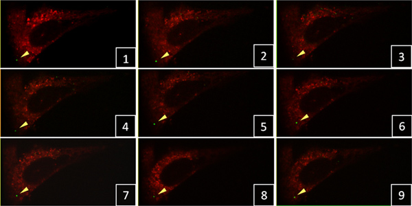
Figure 1. Time-lapse confocal live-cell imaging of HIV-1 particles in HeLa cells. A single green-fluorescent viral particle (yellow arrowhead) was tracked in 3D confocal stacks with a 3 min time interval between frames. Click here to view larger figure.
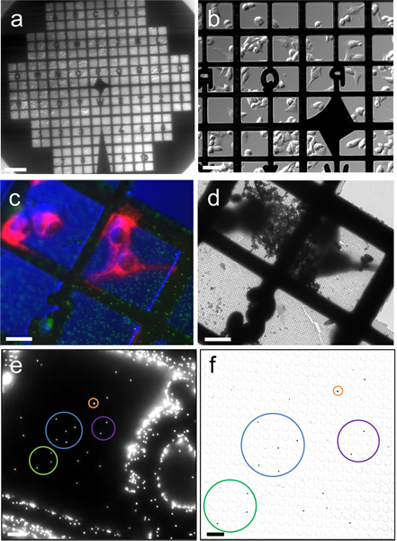
Figure 2. Correlation between fluorescence images and cryoEM images. (a & b) Differential interference contrast (DIC) images of HeLa cells cultured on a Quantifoil gold EM finder grid, recorded with a 2X (a) and 20X (b) objectives. (c) Cryo-fluorescence image of frozen-hydrated HeLa cells (red color for mitochondria) and 0.2 μm fluorescent latex beads (green), recorded with a cryo-stage and a 40X long working distance air objective, overlaid with a DIC image of cells. (d) Low magnification cryoEM image of the corresponding region in (c). (e & f) Correlation between fluorescence and cryoEM images using 0.2 μm fluorescent latex beads. Corresponding beads are circled with the same color. Scale bars, 200 μm in a, 50 μm in b, 25 μm in c, d & e, 5 μm in f.
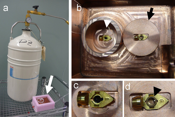
Figure 3. Construction of cryo-light microscopy stage. (a) A self-pressurized dewar, filled with liquid nitrogen, used to cool down the copper cryo-sample stage (white arrow). (b) Top, inside view of the cryo-sample stage, showing the inner chamber (white arrowhead). The sample grid is placed onto the EM specimen cartridge, which sits in the center of a copper block (black arrow). Once loaded with the sample grid, the cartridge is transferred to the inner chamber (white arrowhead) for cryo-fluorescence light microscopy. (c & d) The specimen cartridge before (c) and after (d) placing a copper ring (black arrowhead) to keep the grid in place for using with non-Polara cryo-electron microscope.
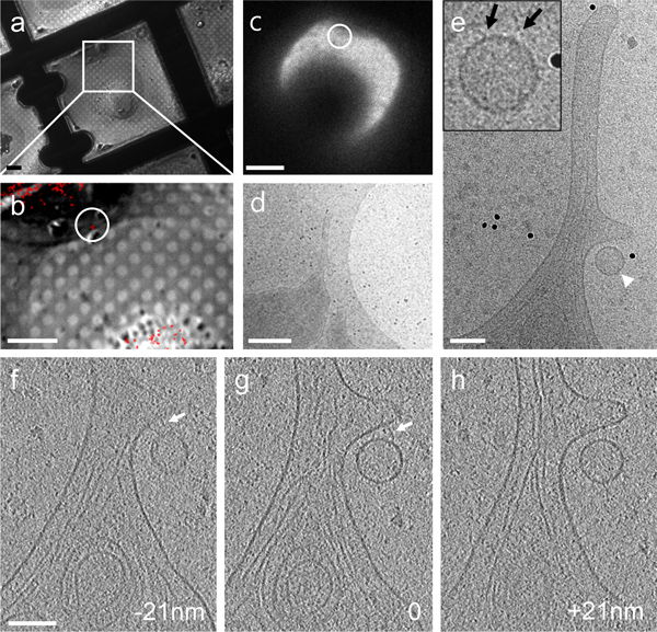
Figure 4. CryoET of a single fluorescent particle bound to the cellular protrusion of a HeLa cell by correlative microscopy. (a & b) A DIC image recorded with a cryo-light microscopy stage (a) overlaid with a cryo-fluorescence image of GFP-tagged particles (red) (b). (c – e) Low dose cryoEM images of the region containing a fluorescent particle (circled in panel b & c) at 140X (c), 3,500X (d) and 27,500X (e), respectively. Inset, an enlarged view recorded after acquisition of the tomographic tilt series. (f – h) Three 4 nm thick tomographic slices separated by a distance of 21 nm in the z direction. Connections between the particle and HeLa cell membrane are indicated by arrows in both the projection image (inset in panel e) and tomographic slices (panels f & g). Scale bars, 10 μm in a & b, 20 μm in c, 500 nm in d, and 100 nm in e – h.
We have presented a straightforward set of protocols to provide an advanced correlative approach to analyze dynamic cellular events using time-lapse confocal, live-cell fluorescence imaging followed by cryoET. Our methodological development to correlate 3D live-cell imaging with high-resolution cryoET is critical to investigate many challenging biological problems, such as visualizing rare, dynamic (not static, as previously reported), and diffraction limited viral particles and their interactions with host cells. The spatial and temporal behavior of specific particles in living cells is characterized by live-cell analysis and the structural details of virus-cell interactions at the defined infection stages are explored. A homemade, cryo-light microscopy stage is used to facilitate direct correlation between fluorescence light images from live cells and images captured by cryoEM.
There are several important points to keep in mind in order to have optimal data collection and analysis. First, when picking multiple positions for time-lapse confocal live-cell imaging, the selected positions should be within 0.5 mm from the center of the EM grid, since the edge of the grid interferes with the field of view for tilt-series acquisition in cryoET. Further, the cells selected for analysis should be between two mitosis phases, when they are most spread-out and flat. Therefore, the thin regions of cells, available for cryoET analysis, are at their most extended stage. In order to have the majority of cultured cells at the same interphase stage, cell cycle can be synchronized using double thymidine treatment that blocks cell cycle at the early S-phase18. Cells released from thymidine block then progress synchronously through G2- and mitotic phase.
Second, as mentioned earlier, the time delay between the last frame of confocal image and cryo-fixation of the sample should be minimized to allow efficient direct correlation of dynamic objects. In addition, the flatness and integrity of the grid are critical for all procedures and must be maintained throughout the protocol, particularly when bare grids are handled for non-Polara microscopes.
Finally, precise and reliable correlation between the fluorescence image and the electron microscopy image, to find the target, is required for successful subsequent acquisition of cryoET data. In a projection image, at a low magnification, the recognition of the shape and direction of a selected cell and sometimes counting holes on the grid are necessary to locate the correlated region in the EM field. Fluorescent latex beads are added to the sample for a more robust and accurate correlation. Using fluorescent latex beads or Quantum dots, which are both fluorescent and electron-dense, the coordinates of the target in fluorescence image can be directly transferred to EM for a precise localization. It should be noted that the emission wavelength of fluorescent latex beads or Quantum dots is chosen not to have overlap with the emission wavelength of the target.
Our current correlation set up for identifying a target area takes place outside of a cryo-electron microscope, thus involving an additional sample transfer step from an optical microscope to an electron microscope. A more direct and straightforward method has been thought out19, by installing a fluorescent imaging apparatus within the electron microscope. In addition, the resolution afforded by a long working distance air objective with NA of 0.6 is limited (~0.6 μm). Precise and accurate nanoscale single molecule localization in 3D cellular tomograms will further involve super resolution microscopy to correlate fluorescent labeled proteins in the ultrastructure.
Further advances in correlative light microscopy and cryoET are expected by combining additional techniques, such as cryo-focused ion beam (FIB) milling9,20 and vitreous sectioning8 of frozen-hydrated specimens. These techniques overcome the limitations of the specimen thickness, greatly expanding the range of samples amenable for cryoET analysis, thus allowing investigation of viral particles that have traveled deep inside of the cells. In terms of the study of virus particle interactions with host cell factors, further double labeling of specific cellular protein and the HIV-1 cores with a tetra-Cysteine fluorescence probe fused to HIV-1 CA could facilitate the identification of particular early stages of the HIV-1 life cycle and the spatial and functional relationship of host factors and viral particles. We anticipate the correlative 3D live-cell imaging and cryoET methodology to play important roles in study cell signaling, membrane receptor trafficking, and many other dynamic cellular processes in cell biology.
The authors have nothing to disclose.
The authors would like to thank Travis Wheeler and the machine shop at the Department of Cell Biology and Physiology, University of Pittsburgh for construction of the cryo-fluorescence sample stage, Changlu Tao and Cheng Xu at the University of Science and Technology of China for technical assistance, and Dr. Teresa Brosenitsch for critical reading of the manuscript. This work was supported by the National Institutes of Health (GM082251 & GM085043).
Reagents | |||
DMEM 4.5 g/L Glucose w/ L-Glutamine | Atlanta Biologicals, Inc. Lawrenceville, GA | 12-604F | |
Fibronectin | Sigma, St. Louis, MO | F1141-1MG | HeLa cell culture on EM grids |
Cell tracker | Invitrogen Corporation, Carlsbad, CA | C34552 | Red CMTPX |
Protein A gold conjugates | Ted Pella, Inc., Redding, CA | 15822-1 | 15 nm diameter |
0.2 μm fluorescent microspheres | Invitrogen Corporation, Carlsbad, CA | F8811 | Yellow-green fluorescent |
Heat-inactivated fetal calf bovine serum | Invitrogen Corporation, Carlsbad, CA | 10082-139 | |
Penicillin-Streptomycin | Invitrogen Corporation, Carlsbad, CA | 15140-122 | |
Glass-bottom culture dish | MatTek Corporation | P35G-1.5-14-C | |
Gold quantifoil finder EM grids | Quantifoil Micro Tools, Jena, Germany | R2/2 Au NH2 200 mesh | |
PBS | Invitrogen Corporation, Carlsbad, CA | 70011-044 | |
Equipment | |||
Glow-discharge device 100X | EMS, Hatfield, PA | ||
Tecnai Polara G2 electron microscope with a Field Emission Gun | FEI, Hillsboro, OR | 300 keV | |
Vitrobot Mark III | FEI, Hillsboro, OR | ||
Olympus IX 71 microscope | Olympus America Inc., Center Valley, PA | LUCPlanFLN 40X/0.6 NA (2.7-4 mm working distance) objective lens | |
Nikon TiE microscope | Nikon Instruments, Melville, NY | using a 60X/1.35 NA oil immersion objective lens | |
Sweptfield confocal microscope | Prairie Technologies, Middleton, WI | ||
Tokai Hit live cell chamber | Tokyo, Japan | ||
Cryo-fluorescence sample stage | Home-made | Homebuilt by machine shop, see reference 15 for the design. |