Many microfluidic devices have been developed for use in the study of electrotaxis. Yet, none of these chips allows the efficient study of the simultaneous chemical and electric-field (EF) effects on cells. We developed a polymethylmethacrylate-based device that offers better-controlled coexisting EF and chemical stimulation for use in electrotaxis research.
The behavior of directional cell migration under a direct current electric-field (dcEF) is referred to as electrotaxis. The significant role of physiological dcEF in guiding cell movement during embryo development, cell differentiation, and wound healing has been demonstrated in many studies. By applying microfluidic chips to an electrotaxis assay, the investigation process is shortened and experimental errors are minimized. In recent years, microfluidic devices made of polymeric substances (e.g., polymethylmethacrylate, PMMA, or acrylic) or polydimethylsiloxane (PDMS) have been widely used in studying the responses of cells to electrical stimulation. However, unlike the numerous steps required to fabricate a PDMS device, the simple and rapid construction of the acrylic microfluidic chip makes it suitable for both device prototyping and production. Yet none of the reported devices facilitate the efficient study of the simultaneous chemical and dcEF effects on cells. In this report, we describe our design and fabrication of an acrylic-based multichannel dual-electric-field (MDF) chip to investigate the concurrent effect of chemical and electrical stimulation on lung cancer cells. The MDF chip provides eight combinations of electrical/chemical stimulations in a single test. The chip not only greatly shortens the required experimental time but also increases accuracy in electrotaxis studies.
The behavior of adherent cells moving toward an anode or cathode under a direct current electric-field (dcEF) is referred to as electrotaxis. The electrotactic behavior of cells plays a significant role in embryogenesis, nerve regeneration, and wound healing.1 Tumor cells such as rat prostate cancer cells,2 breast cancer cells,3 and lung adenocarcinoma cells4-8 have shown electrotactic movement under an applied dcEF. The physiological EF has been measured in gland tissues.9,10 Electrotaxis has also been reported in gland-associated tumor cells.2,3 Taken together, the electrotaxis of cancer cells is considered to be a metastasis factor.11 Controlling the electrical guidance of cancer cells under dcEF may be a potential approach for the future treatment of cancer. However, today, the detailed molecular mechanism of electrotaxis remains controversial. Therefore, an investigation of the influence of electrical stimulation on cancer cell migration can facilitate the development of strategies for cancer treatment.
Recently, bio-microfluidic devices have been fabricated for studying cellular responses to flow shear force,12 chemical gradients,13 and electrical stimuli4 in vitro. The fabrication of bio-microfluidic devices using polydimethylsiloxane (PDMS) or polymethylmethacrylate (PMMA, also known as acrylic) has successfully reduced the failure rate of such experiments. Moreover, using acrylic-based microfluidic devices as a prototype for investigating biological subjects is simpler than using PDMS chips. Various functions in acrylic-based devices have been developed for electrotaxis study. However, none of the previous designs are able to simultaneously test the effects of various chemical conditions and the electric-field on cells for electrotaxis study. Thus, we developed a microfluidic device-the multichannel dual-electric-field (MDF) chip-containing four independent culture channels and eight different experimental conditions in one chip.
The acrylic-based MDF chip, first reported by Hou et al.,8 integrates electrical stimulation and several chemically isolated channels. These chemically isolated channels can be used to culture different types of cells in one experiment. The dcEF in the channels is produced by an electrical power supply. Two independent electric fields, one with applied electric-field strength (EFS) and another with 0 EFS, are conducted in each chemically isolated channel. In this way, the chip provides better-controlled coexisting EF and chemical stimulation. Furthermore, results from the numerical simulation of the chemical diffusion inside the MDF chip indicate that no cross contamination occurred between the channels after a 24 hr experimental period.8
Compared to the device reported by Li et al.,14 the MDF chip provides a larger culture area, which allows for further biochemical analysis of the electrically stimulated cells. Additionally, with the MDF chip's larger observation area, more cells can be observed in the test, so the analysis of migration speed or directedness of the electrically stimulated cells is more accurate. The single-channel chip designs of previous studies reported by Huang et al.4 and Tsai et al.15 allow only one type of cell or chemical to be tested. However, the MDF chip can be used to investigate the effects of various chemicals on electrotaxis, as well as the effects of electrical stimulation on different types of cells. In other words, the MDF chip allows for the efficient study of chemical dose dependencies.
1. Design and Fabrication of the MDF Chip
2. Setup of the Salt Bridge Network of the MDF Chip
3. Preparation of Cancer Cells and Set Up for Electrotactic Experiment
4. Set Up for Electrotactic Experiment
5. Acquisition and Analysis of Cell Images
Fabrication and assembly of the MDF device
A schematic diagram of the acrylic-based MDF chip is shown in Figure 1A. Four acrylic sheets, one cover glass, 13 acrylic adaptors, and a piece of double-sided tape were used in the assembly of the completed MDF chip (Figure 2D). There are only four independent culture channels in the MDF device. However, the on-chip salt bridge network creates eight different experimental conditions in the eight segments of the chip. Three salt bridges (the blue channels in Layer 2 of Figure 1A), 79, 90, and 80 mm in length, were coupled to the second layer of the MDF chip without interfering with the image observation. The small pores (blue cuboid channels in Layers 3 and 4 of Figure 1A) between the salt bridge network and the culture chambers, which have a 0.25 mm2 cross-section area, minimized the fluid flux into the salt bridge during the experiment. The culture area of the MDF chip is about 74 mm2 in each segment. In this demonstration, the cell culture chambers of the MDF device are composed of the 70 μm thick double-sided tape and cover glass. However, if different cell culture conditions (e.g., a collagen coating requirement, low flow shear, or large culture medium volume in the culture chamber) is needed for electrotaxis research, both the culture substrates and the tapes could be easily replaced. Therefore, various types of cells can be used for electrotaxis study within the MDF chip.
Configuration of MDF microfluidic system
The MDF microfluidic system setup is illustrated in Figure 3A. The components shown in Figure 3B are used to establish medium flow and the electrical current network in the MDF microfluidic system. The tubes connected with the hollow finger-tight nuts (red and green) and Luer tapers (brown) in Figure 3B-i are used to transport medium to the MDF flow network. After the syringes were connected to the Luer tapers and settled onto the four-channel pump, the pipeline flow system was complete. Culture medium and waste are transported through the pipeline system. Because the connection between the tubes and acrylic adaptors are fastened by screwed connectors, the MDF medium network can tolerate higher hydraulic pressure than can the PDMS system. Due to the extreme low air permeability of the acrylic sheets and the tubes, any contact between the medium network and the outside environment is blocked. Therefore, the pH value of the medium in the system remains stable, and cells can be cultured using the MDF microfluidic system outside a CO2 incubator. Since the MDF chip is installed on a motorized stage, time-lapse cell images can be taken from eight individual sections. The open-bottomed microcentrifuge tubes (Figure 3B-ii) are mounted on the translucent tubular finger-tight nuts (Figure 3B-iv) to increase the volume capacity of agarose. In this way, relatively large electrodes can be inserted into the agarose to provide stable electrical stimulation to the cells for longer periods of time.
Generation of indicated direct current electric field in the MDF chip
The voltage of each chamber can be measured via the implanted electrodes in the electric circuit-connected chip. However, we did not measure the voltage in the chamber. Rather, we simulated the electric field in the salt bridge network and the cell culture chambers of the chip. Four electrotactic chambers were serially connected in the electric circuits. In this way, the same electric current is maintained in each of these chambers. According to Ohm's law, the EFS correlates with the area of the cross-section of the chambers in the microfluidic device. Additionally, all the PMMA sheets and tapes were fabricated by the CO2 laser scriber. The alignment of the chip assembly pieces is precise and the structural defects of the chip are minimal. Thus, the EFS in each chamber should remain stable. The electric field simulation results show a homogeneous distribution of EFS with 300 and 0 mV/mm in the first halves and the remaining halves of the culture chambers in the device (data not shown). Previously, reports from our lab, Huang et al. and Tsai et al., have demonstrated that the difference in the measured and the simulated EFS values was less than 4%.4,15 This result shows that, in our system, the measured electric field corresponds well with the simulated value. In this work, we inserted large Ag/AgCl electrodes to provide stable electrical current for a lengthy experiment. The applied current on the MDF chip decreased only 1.85 ± 0.19% after 7 hr of EF stimulation in the electrotaxis experiments. Furthermore, the longest period of electrical stimulation was 4 hr in our study. Thus, we believe the input electric current remains stable during electrotaxis testing, and the electric field in the electrotactic chambers of the MDF chip are monitored by the serially connected ammeter.
Investigation of the electrotaxis of lung cancer cells using the MDF microfluidic system
The electrotactic regulation of Rho-associated coiled-coil kinase (ROCK) has been demonstrated in Chinese hamster ovary (CHO),20 endothelial,21 and neuronal cells22 but has yet not been investigated for lung cancer cells. Therefore, the ROCK inhibitor, Y27632, was applied to the MDF microfluidic system to study its effect on the electrotaxis of lung cancer cells. As shown in Figure 4, treatment of Y27632 showed no effect in altering the cell migration speed with or without electrical stimulation. However, the application of Y27632 to cancer cells under dcEF (300 mV/mm) significantly reduced their anodic migration. At 50-μM concentration, the ROCK inhibitor eliminated the anodic movement of lung cancer cells but did not affect their migration speed. Moreover, there was a dose-dependent correlation between the applied chemical concentrations and the directedness index (Figure 4B). These results suggest that the MDF microfluidic system is reliable and efficient for studying electrotaxis.
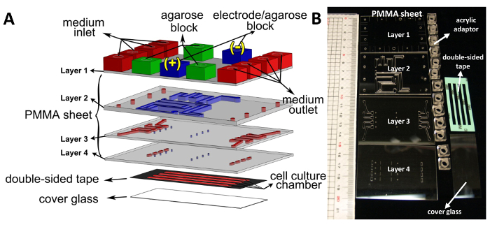
Figure 1. Design of the MDF chip. (A) Schematic drawing of the MDF chip. The MDF device consists of four layers of acrylic sheets (72 × 50 mm), 13 acrylic adaptors (10 × 10 × 6 mm), double-sided tape, and a cover glass (24 × 60 mm). The thickness of the Layer 2 acrylic sheet is 2 mm and the other three layers are each 1 mm. In the lower three acrylic layers, the salt bridge and medium flow networks are represented by the blue and red blocks, respectively. In the first acrylic sheet layer, green acrylic adaptors were used for the injection of agarose. Blue acrylic adaptors were used as the connection to the Ag/AgCl electrodes. There are four cell culture chambers in the MDF chip. The area and height of each cell culture chamber are 148 mm2 (3 × 46 mm) and 0.07 mm, respectively. The small blue channels on the Layers 3 and 4 connect the salt bridge network to the culture chambers. The cross-section of these connection channels is 0.25 mm2 (0.5 × 0.5 mm) (reprinted with permission from Hou et al.,8 copyright 2014, American Institute of Physics). (B) Photograph of all components of the MDF device assembly, comprising PMMA sheets, acrylic adaptors, double-sided tape, and cover glass. Please click here to view a larger version of this figure.
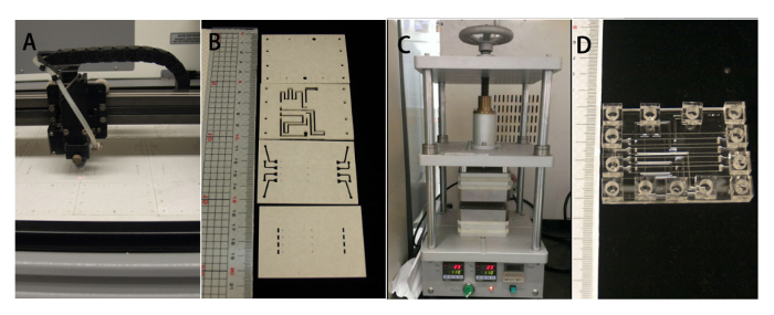
Figure 2. MDF chip fabrication and assembly processes. (A) The patterns of the acrylic sheet and double-sided tape were scribed by CO2 laser machining. (B) The individual acrylic sheet layers were fabricated by a CO2 laser according to the design drawing. (C) The cleaned acrylic sheets were bonded together using a thermal bonder. (D) Completed MDF chip assembly. Please click here to view a larger version of this figure.
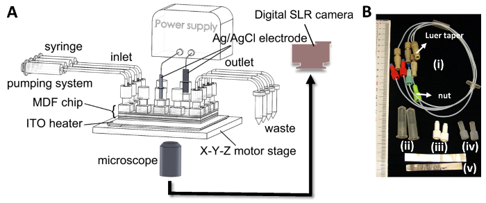
Figure 3. System for electrotaxis study. (A) Schematic diagram of the system for the electrotaxis experiment. The tubes connected to the MDF chip were used for medium infusion and waste efflux. The dcEF in the chip was conducted through the Ag/AgCl electrodes and power supply. The device setup was installed on the X-Y-Z motor stage of a microscope. Cell images in the chip were taken by a commercial digital SLR camera. (B) Photograph of the components of the medium flow network and the dcEF generation in the MDF microfluidic system, including (i) the tube connector, (ii) open-bottomed microcentrifuge tubes, (iii) white solid finger-tight nut, (iv) translucent tubular finger-tight nut, and (v) Ag/AgCl electrodes. Please click here to view a larger version of this figure.
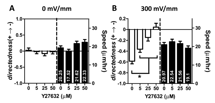
Figure 4. Effect of Y27632 on lung cancer cell migration under the EFS of (A) zero and (B) 300 mV/mm. dcEF stimulation was applied after a 1 hr pretreatment with the indicated concentration of Y27632. The electrical stimulation lasted for 2 hr. The quantitative analysis of the directedness and the speed of the cell migration consititute a representative experiment. 90-100 cells were used in the data analysis. *for P <0.001. Data are expressed as the mean ± standard error of the mean (SEM). Please click here to view a larger version of this figure.
We found the process of adhering acrylic adaptors onto Layer 1 of the MDF chip to be tricky. The application of just 1 to 2 μl of super glue is sufficient to firmly adhere the adaptor onto the MDF chip. Larger amounts of glue resulted in an incomplete polymerization of the super glue and failure to adhere. Once the acrylic adaptors were firmly adhered onto the MDF chip, liquid leakage in the microfluidic system rarely occurred. In addition, O/N incubation inside the vacuum chamber helped to remove the air trapped between the double-sided tape/cover glass or double-sided tape/acrylic sheet interface. Consequently, this process enhances the stability of the culture chamber in the MDF chip.
Temperature control of the 3% agarose during the preparation of the salt bridge network is important. If the temperature of the agarose is not high enough during the injection, the agarose will quickly solidify inside the syringe and cannot be injected into the salt bridge network. Moreover, during agarose injection, it is important to avoid any bubble formation in the salt bridge network. The appearance of bubbles greatly increases the electrical resistance of the network and leads to experimental failure. In addition, once the agarose solidifies during the injection, it cannot completely block liquid flow in the salt bridge channel. As such, the chemicals can then easily leak into other channels. The best approach is to inject hot agarose into the network and to then allow the agarose to solidify inside the salt bridge channels.
Cell injection is a critical process in the electrotaxis experiment. To ensure a sufficient number of cells for cell seeding in the culture chamber, we injected excess number of cells. In this approach, cells were injected from the outlet. The injection speed should be slow and even to avoid an uneven cell distribution in the culture chamber. In addition, because the channels are isolated in the MDF chip, the injection must be done one channel at a time. Thus, the complete cell injection process is time-consuming. In the future, it will be necessary to create an additional cell injection channel that can simultaneously implant cells into all four culture chambers. This new process will reduce sample volume, the number of cells required for injection, and the operation time.
There are several advantages in using acrylic rather than PDMS as the material for fabricating the microfluidic device. An acrylic-based device can be operated directly on a heater without an incubator. Since the system requires no CO2 supply, cells can be grown in an acrylic-based bio-microfluidic chip on a regular inverted microscope with the heater. It is easier to record cell images in the chip outside of an incubator. We used a widely available commercial digital SLR camera to record the cell images in the system. In addition, the software necessary for programmable control of the camera is also easily available. This makes time-lapse imaging of the cells easily programmable. Therefore, the cost of building the bio-microfluidic auto-recording image system is much lower than that of a commercial system. In contrast, when using a PDMS-based chip, the system must be operated in a CO2 incubator. Thus, extra image recording equipment must be purchased for operation in the incubator. Such equipment is expensive, relatively bulky, and occupies a large portion of the limited space in the cell culture incubator. In another aspect, compared to the process of PDMS chip fabrication, the easy and rapid fabrication of the acrylic microfluidic chip is suitable for both device prototyping and production. Moreover, compared with the PDMS-based device, the acrylic-based microfluidic chip is structurally more stable and more suitable for constructing a complicated three-dimensional microfluidic network system, as was performed with the MDF chip in this study. The on-chip salt bridge network in the MDF chip cannot be easily produced in a PDMS-based device. This network system minimizes the total size of the microfluidic chip and makes electrotaxis research easier and faster.
Inside the MDF chip, we generated only two electric-field strengths (EFS, 0 and 300 mV/mm) in each isolated channel. However, the MDF chip and the multi-field electrotactic chip, as reported by Huang et al.,4 share a similar channel design in the cell culture region. By altering the shapes of the culture chamber in the MDF chip, multiple EFSs can also be generated on the MDF chip. With these modifications, multiple EFSs and multiple chemicals may be used in the same test. Accordingly, a high throughput screening system could be created to investigate electrotaxis using the device.
In just one experiment, the MDF chip is capable of testing the effects of different chemicals on cells under dcEF, or the influences of electrical stimulation on different types of cells. It may even be possible to implement 20 isolated parallel channels in the MDF chip without significantly increasing the size of the device.8 As demonstrated in this work, in one experiment, we obtained a significant dose-dependent correlation between the directedness of cell migration and Y27632 (Figure 4). The MDF chip with four channels clearly provides an efficient approach for studying electrotaxis in cancer cells.
The authors have nothing to disclose.
This work is financially supported by the Ministry of Science and Technology, Taiwan (Contract no. MOST 103-2113-M-001 -003 -MY2) and the Research Program on Nanoscience and Nanotechnology, Academia Sinica, Taiwan.
Reagent | |||
DMEM medium | Gibco,Invitrogen, USA | 12800-017 | |
Fetal Bovine Serum | Gibco,Invitrogen, USA | 16000-044 | |
Trypsin | Gibco,Invitrogen, USA | 25200-072 | |
PBS | Basic Life | BL2651 | |
Y-27632 (hydrochloride) | Cayman Chemical Co | 10005583 | |
agarose | LONZO, USA | SeaKem LE AGAROSE | |
syringe | Terumo | 3 ml with Luer taper | |
3-way stopcock | Nipro | with Luer taper | |
PMMA (acrylic) | HiShiRon Industries CO., Ltd, Taiwan | thickness 1mm, 2mm | |
acrylic adaptor | KuanMin Technology Co., Ltd, Taichung, Taiwan | 1/4-28 port, 10x10x6 mm | customized |
nut | Thermo Fisher Scientific Inc. | UPCHURCH:P-206x, P-200x, F120x, P-659, P-315x | |
Microscope cover glass | Deckgläser, Germany | 24×60 mm | |
double-sided tape | 3M | PET 8018 | |
super glue | 3M | Scotch Liquid Plus Super Glue | |
Teflon tube | HENG YI ENTERPRISE CO., LTD., Taiwan | UPTB_06, DUPONT TEFLON BRAND RESIN FEP TUBING | outer diameter 1/16 in., inner diameter 0.03 in.; Upchurch Scientific |
TFD4 detergent | Franklab, France | TFD4 | |
ultrasonic steri cleaner | LEO ULTRASONIC CO., LTD., Taiwan | ||
Thermo bonder | KuanMin Technology Co., Ltd, Taichung, Taiwan | customized | |
CO2 laser scriber | LTT group, Taiwan | ISL-II | |
indium tin oxide glass (ITO glass) | AimCore Technology Co., Ltd | TN/STN, ≦10Ω | |
proportional-integral-derivative (PID) controller | JETEC Electronics Co., Japen | TTM-J40-R-AB, | |
K-type thermocouple | TECPEL | TPK-02A | |
4-channel syringe pump | KdScientific, USA | 250P | |
DC power supply | GWInstek, Taiwan | ||
X-Y-Z motor stage | TanLian, E-O Co. Ltd., Taiwan | customized | |
inverted microscope | Olympus, Japan | CKX41 | |
digital SLR camera | Canon, Japan | 60D |