Calculations performed by the Vienna Ab initio Simulation Package can be used to identify the intrinsic electronic properties of nanoscale materials and predict the potential water-splitting photocatalysts.
Computational tools based on density-functional theory (DFT) enable the exploration of the qualitatively new, experimentally attainable nanoscale compounds for a targeted application. Theoretical simulations provide a profound understanding of the intrinsic electronic properties of functional materials. The goal of this protocol is to search for photocatalyst candidates by computational dissection. Photocatalytic applications require suitable band gaps, appropriate band edge positions relative to the redox potentials. Hybrid functionals can provide accurate values of these properties but are computationally expensive, whereas the results at the Perdew-Burke-Ernzerhof (PBE) functional level could be effective for suggesting strategies for band structure engineering via electric field and tensile strain aiming to enhance the photocatalytic performance. To illustrate this, in the present manuscript, the DFT based simulation tool VASP is used to investigate the band alignment of nanocomposites in combinations of nanotubes and nanoribbons in the ground state. To address the lifetime of photogenerated holes and electrons in the excited state, nonadiabatic dynamics calculations are needed.
The worldwide demand for clean and sustainable energy has spurred research for promising materials to reduce dependence on finite petroleum resources. Simulations are more efficient and economical than experiments in accelerating the search for new functional materials1. Material design from a theoretical perspective2,3,4 is now more and more popular due to rapid advances in computational resources and theory developments, making computational simulations more reliable5. The density functional theory (DFT) calculations implemented in many codes are becoming more robust and yield reproducible results6.
The Vienna Ab initio Simulation Package (VASP)7 presents one of the most promising DFT codes for predicting molecular and crystalline properties and more than 40,000 studies making use of this code have been published. Most work is performed at the Perdew-Burke-Ernzerhof (PBE) functional level8, which underestimates the band gap sizes, but captures the essential trends in band alignment and band offsets3. This protocol aims to outline the details of investigating the band edge profiles and bandgaps of nanoscale materials for clean and renewable energy using this computational tool. More examples using VASP are available at https://www.vasp.at.
This report presents the computational screening of one-dimensional (1D) vdW heterostructures with type II band alignments9 for a promising application in photocatalytic water splitting4. Specifically, nanoribbons (NRs) encapsulated inside nanotubes (NTs) are examined as an example10. To address noncovalent interactions, vdW corrections using the DFT-D3 method are included11. The DFT calculations in steps 1.2, 2.2, 3.2, 3.5.2, and section 4 by VASP are performed using a Portable Batch System (PBS) script by the high-performance research computers in the CenTOS system. An example of a PBS script is shown in the Supplementary Materials. The data postprocessing by the P4VASP software in step 3.3 and the figure plot by the xmgrace software in step 3.4 are carried on a local computer (laptop or desktop) in the Ubuntu system.
1. Optimize the atomic structure.
2. Calculate the encapsulation energy.
3. Extract the electronic properties from the band structure.
4. Modulate the electronic properties of the nanocomposite (NT encapsulated inside NR) by external fields.
Zigzag BN-NRs encapsulated inside armchair BN-NTs (11,11) were chosen as representative examples for a 1D vdW heterostructure. The lattice parameters were taken from Sahin et al.20. For convenience, zigzag NRs are abbreviated Zn, where n represents the III–V dimers along the width14. The encapsulation energy EL from step 2.3 was used as a rough estimate for the energetic stability of the nanocomposite. The EL values of Z2, Z3, and Z4 encapsulated inside BN-NT (11,11) were -0.033 eV/Å, -0.068 eV/Å, and -0.131 eV/Å, respectively10, as shown in Figure 1. Although EL varied by an order of magnitude with BN-NR size, all three nanocomposites presented type II band structures (from step 3.4) superior to the all-carbon cases14, where type II only emerged for NR with only one appropriate size inserted in NT14.
The band structure of the nanocomposite from step 3.2, BN-NT (11,11) + Z4, is shown in Figure 2. VBM/CBM locates at NT/NR (from step 3.5), respectively. The staggered band alignment was beneficial for light harvesting. The main mechanism of charge transfer is as follows: the photo generates electrons and a hole in Z4 at the X point, shown in Figure 3, and then the hole dissociates from Z4 (kX) to NT (11,11) (kVBM, the k point of VBM for this nanocomposite), shown in Figure 4. The calculated VBO (from step 3.4.3) is 317 meV, larger than the thermal energy at 300 K (KT ~30 meV), and effectively decreases the recombination rate of the photogenerated carriers10.
To enhance light harvesting through a wide spectrum, both transverse electric fields and longitudinal tensile strains are applied to BN-NT (11,11) + Z4. The evolution of band edges relative to the vacuum level from step 4 is shown in Figure 5. A substantial gap reduction up to near 0.95 eV is observed in this nanocomposite by external fields. More importantly, the staggered band alignment is preserved10. Based on these results, such a 1D system is expected to integrate photocatalytic hydrogen generation and safe capsule storage21. The photogenerated electrons could be collected by NR. Driven by electrostatic attraction, protons penetrate through the NT to generate a hydrogen molecule. The produced hydrogen is completely isolated within the nanotube to avoid an unwanted reverse reaction or explosion.
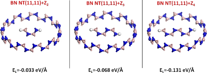
Figure 1: Zigzag BN nanoribbons Z2, Z3, and Z4 encapsulated inside a BN nanotube (11,11). The encapsulation energy (EL) is listed under each structure. Please click here to view a larger version of this figure.
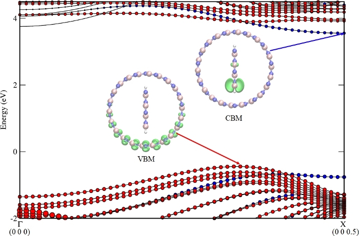
Figure 2: Band structure of BN nanotube (11,11) + BN nanoribbon Z4. The contributions from the nanotube and nanoribbon to the energy bands are represented in red and blue spheres, respectively. The left insets show the charge density distributions of the CBM and the VBM states (isovalue 0.02 e/Å3). This figure was adapted from Gong et al.10 with permission from The Royal Society of Chemistry. Please click here to view a larger version of this figure.
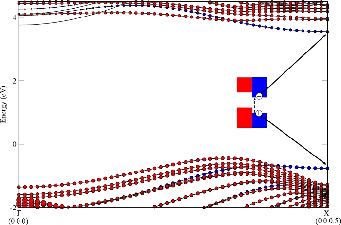
Figure 3: The photo generates electrons and a hole in the BN nanoribbon Z4 at the X point. Please click here to view a larger version of this figure.
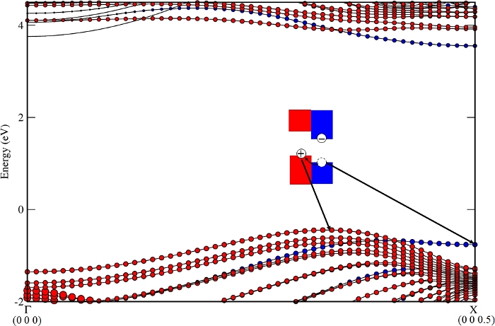
Figure 4: The hole dissociates from the BN nanoribbon Z4 (kX) to the BN nanotube (11,11) (kVBM, the k point of VBM for this nanocomposite). Please click here to view a larger version of this figure.
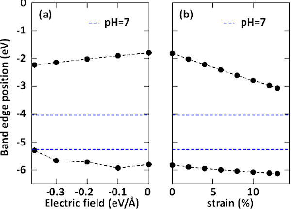
Figure 5: Band edge modulation of the BN nanotube (11,11) and the BN nanoribbon Z4 by external fields. Evolution of band edges relative to the vacuum level under (A) an electric field and (B) uniaxial tensile strain. The negative direction of electric field is denoted from the lower edge atom B to the upper edge atom N of Z4. The reduction potential of H+/H2 and the oxidation potential of O2/H2O are -4.44 eV and -5.67 eV at pH = 0, respectively. The pH = 7 shifts the water’s redox potentials (by pH x 0.059 eV) to -4.027 eV and -5.257 eV, respectively, shown as blue dashed lines. This figure was reproduced from Gong et al.10 with permission from The Royal Society of Chemistry. Please click here to view a larger version of this figure.
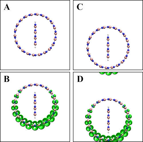
Supplemental Figure 1: (A) Atomic structure of a BN nanotube (11,11) + BN nanoribbon Z4 arranged away from the boundary and its corresponding conduction band minimum (B). (C) Atomic structure of a BN nanotube (11,11) and BN nanoribbon Z4 aligned with one boundary and its corresponding conduction band minimum (D). Please click here to view a larger version of this figure.
Supplementary Coding File: Please click here to view this file (Right click to download).
The calculations for electronic properties in sections 2, 3, and 4 would be similar among various nanoscale materials. The initial atomic model in step 1 should be carefully designed to extract meaningful information. For example, the factor for selecting the model could be the size or chirality of the materials. Also, the initial atomic model in step 1.1 should be reasonably prepared for low-cost structure relaxation. Taking the nanocomposite in the protocol as an example, the NR should be encapsulated inside the NT in a symmetrical manner. Otherwise, it will be time consuming to search the optimized structure by VASP.
To consider the effect of an electric field, an artificial dipole sheet is added in the middle of the vacuum part in the periodic unit cell in VASP22. The vacuum region should not be too broad and the electric field should be weak enough to avoid artificial field emission23.
Whereas the effect of the strain can be simply realized by changing the lattice parameter in POSCAR, in the nanocomposite the situation would be more complex. The elastic responses of the NR and NT may be different from each other, undergoing the same strength. This will lead to a disproportionate structure. For example, when the uniaxial tensile strain is applied along the periodical direction, the optimized lattice parameter of the NT and NR along this direction changes from an initial 1.8 Å to 2.0 Å, and 2.2 Å, respectively. Large supercells are required for modeling: at least 11 unit cells of NT and 10 unit cells of NR in this case (11 x 2.0 Å = 10 x 2.2 Å = 22 Å).
While ground state electronic properties of materials can be determined by VASP quite well, to address the lifetime of photogenerated holes and electrons existing in an excited state, it is better to perform nonadiabatic dynamics calculation24. This is important to design photocatalysts with long lifetime carriers4.
The role of the computational approach performed by VASP plays into the discovery of novel materials and the screening for potential photocatalysts to assist experimental efforts. The band alignment at the PBE level in water splitting is not as convincing as quantitative experimental work. More accurate values of the band edges relative to the redox potentials, CBO, and VBO are needed. It would be best to use the Heyd-Scuseria-Ernzerhof (HSE) hybrid functional25, but it is more time consuming than PBE. Nevertheless, the results at the PBE level could be efficient for suggesting strategies for the enhancement of photocatalytic activity.
It should be mentioned that the computational design by VASP will also enable the prediction of solar cell materials, thermoelectric materials, lithium battery materials, gas capture materials, etc.2. High-throughput calculations have been combined with the machine learning procedures for better materials prediction and lower computational cost26,27.
The authors have nothing to disclose.
This work was supported from China Postdoctoral Science Foundation (Grant No. 2017M612348), Qingdao Postdoctoral Foundation (Grant No. 3002000-861805033070) and from the Young Talent Project at Ocean University of China (Grant No. 3002000-861701013151). The authors thank Miss Ya Chong Li for preparing the narration.
Nanotube Modeler | Developed by Dr. Steffen Weber | NanotubeModeler1.8 | http://www.jcrystal.com/products/wincnt/NanotubeModeler.exe |
P4VASP | Orest Dubay | p4vasp 0.3.30 | Open source, available at www.p4vasp.at |
v2xsf | Developed by Dr. Jens Kunstmann | v2xsf | http://theory.chm.tu-dresden.de/~jk/software.html |
VASP software | Computational Materials Physics, Dept. of Physics, University of Vienna | vasp.5.4.1 | https://www.vasp.at |
VMD software | Theoretical and Computational Biophysics Group, University of Illinois at Urbana-Champaign | vmd1.9.3 | https://www.ks.uiuc.edu/Research/vmd |
xcrysden | Dept. of Physical and Organic Chemistry, Jozef Stefan Institute | XCrySDen1.5.60 | http://www.xcrysden.org/ |
Xmakemol | Developed by M. P. Hodges | xmakemol5.16 | https://www.nongnu.org/xmakemol/XmakemolDownloads.html |
Xmgrace software | Grace Development Team under the coordination of Evgeny Stambulchik | xmgrace5.1.25 | http://plasma-gate.weizmann.ac.il/Grace/ |