1. Irradiation platform and determination of irradiation parameters
- Use an irradiation platform delivering low to medium energy X-rays. Determine the parameters of the experiment to ensure the robustness and the reproducibility of the radiobiological experiment: High voltage, Intensity, Filtration (inherent and additional), Half Value Layer (HVL), Effective energy, Detector used for dosimetry measurements, Source Sample Distance (SSD), Irradiation field (shape, size, geometry), Dosimetry quantity, Dosimetry method, Dose rate, Cell container and Quantity of cell culture media. All parameters used in this protocol are given in Table 1.
2. Beam quality index: determination of the half value layer
NOTE: The HVL is defined as the thickness of an attenuator (usually copper or aluminum) to reduce the intensity of the beam by a factor of two compared with the original value.
- Set up the equipment (support, collimator, diaphragm, ionization) inside the irradiation enclosure by following the instructions in Figure 1. No attenuator material is used at this step.
- Ensure that all the distances reported in Figure 1 are correct. Measure these with a tape measure.
- Place that the ionization chamber in the horizontal position. For this work, we used a 31002 (equivalent to 31010) cylindrical ionization chamber calibrated in air kerma.
- Pre-irradiate the ionization chamber for 5 min and measure the background (this step can be performed without a collimator).
- Perform 10 measurements of 1 min each in charge collection mode corresponding to the Mraw value (in coulombs).
- Take the temperature and pressure with suitable calibrated equipment placed inside the irradiation enclosure in our case (if it is not possible, place it near to the experiment). Correct the Mraw reading on the electrometer by the temperature and pressure correction factor given as follows:
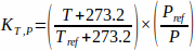
where: T (°C) and P (hPa) are the actual temperature and pressure, respectively. Tref and Pref are the reference temperature and pressure when the ionization was calibrated by the standards laboratory. The pressure and temperature must be measured with calibrated instruments. The obtained value in charge mode is the average reference value M (in coulombs).
NOTE: This step is not strictly necessary for HVL measurement, but it is recommended. - Place an attenuator of certain thickness above the diaphragm. The HVL set is composed of foils with different thicknesses (0.02, 0.05, 0.1, 0.2, 0.5, 1, 2, 5 and 10 mm of copper) with a dimension allowing to cover the entire beam (80 x 80 mm here).
- Take a measurement of 1 min (Mraw corrected by the KT,P as described before).
- If the dose rate is divided by a factor of 2 with respect to the starting value, the HVL value is found. Take 5 measurements of 1 min to estimate the average dose rate.
- If the dose rate is not divided by a factor of 2 with respect to the starting value, increase or decrease the attenuator thickness and take another measurement. Adjust the thickness of the attenuator as necessary.
- Once the thickness of the attenuator that decreases the intensity of the beam by a factor two is found, take 5 measurements of 1 min to confirm the HVL.
NOTE: In most cases, the exact thickness of the attenuator cannot be found from the foils available. In this case, proceed by bisection and interpolate the HVL.
3. Evaluation of the irradiation field (no dose estimation)
- Place an EBT3 film on the support used for irradiation.
- Irradiate this film to obtain a well-marked irradiation field (at least 2 Gy).
- Scan the EBT3 film using a dedicated scanner.
- Plot the dose profile using Image J using the Analyze and then Plot Profile option (Figure 2).
- Determine the size of irradiation field usage for irradiation (homogeneous area, excluding penumbra regions, see Figure 2).
- Make marks on the support used for irradiation to ensure that the cell container is in the right position.
NOTE: In this step, the size of the irradiation field is determined, and the dose is not estimated. The complete procedure for film reading and analysis is given in section 5. Also, take margins in order to avoid errors due to the cell container positioning.
4. Dose rate measurement with ionization chamber
- Take the cell container and break a little part on the side or at the bottom (depending on the particular container and ionization chamber used) to be able to place the ionization chamber inside (Figure 3, upper section) or below (Figure 3, lower section) the container. The examples are given in Figure 3 with different ionization chambers (cylindrical or plane parallel) and cell containers. In this case, a T25 flask was used (Figure 3, red box).
NOTE: a soldering iron or heated scalpel is a good alternative to make holes in plastic ware - Place the container inside the enclosure on the support used for irradiation (carbon plate here).
- Place the ionization chamber in the container (Figure 3, red box), in the correct position and connect it to the electrometer.
- Ensure that all irradiation parameters listed in section 1 are correct (high voltage, intensity, additional filtrations, source sample distance, etc.).
- Pre-irradiate the ionization chamber for 5 min and perform the zeroing of the electrometer.
- Take 10 measurements of 1 min to determine the average dose rate in air kerma (Gy.min-1). Calculate the determination of the dose rate in Kair as follows:
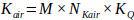
where M is the reading of the dosemeter corrected by temperature, pressure, polarity effect, ion recombination, and electrometer calibration. NKair and Kq are the calibration and correction factors for radiation quality, whose values are specific to each ionization chamber.
5. Measurement of cell culture media attenuation and scattering
NOTE: Handle EBT3 films with gloves throughout the procedure.
- Preparation of the experiment
- Cut small pieces of EBT3 films at least 24 h before irradiation.
- Determine the size of the films as a function of the cell container used for radiobiology experiments (4 x 4 cm for a T25 flask, for example).
Cut two sets of radiochromic films: One set for the calibration curves composed of three pieces of EBT3 radiochromic film by dose or time point (nine points in total for this work) ; and one set for the quantification of the cell culture media attenuation, also three pieces per point. - Number all the films for identification (upper-right corner here) and scan them on the same position on the scanner.
- Keep the films away from light.
- Prepare the cell container used for the EBT3 film measurements and, if necessary, cut a part to put the film inside (an example with a T25 is given in Figure 4).
- Dose rate estimation
- Measure the dose rate for the configuration as described in the previous section.
- Keep this configuration in place for the irradiation of the EBT3 radiochromic films and use the same type of cell container.
- Construction of the calibration curve
- Take the pre-cut EBT3 films for the calibration curve.
- Do not irradiate three pieces (0 Gy).
- Place the first film inside the cell container, in the same configuration as for cell irradiation.
- Irradiate it to obtain the first dose points.
- Repeat this operation to obtain three pieces of EBT3 films irradiated with the same dose.
- Perform this for each dose point (nine dose points in this work (0, 0.25, 0.5, 0.75, 1, 1.5, 2, 2.5, and 3 Gy) as illustrated in Figure 5).
- Evaluation of the attenuation of cell culture media and scattering.
- Chose the same irradiation time for all irradiations (60 s, for example).
- Irradiate three pieces of EBT3 films in the container without water.
- Irradiate three pieces of EBT3 films in the container with water as follows.
- Place the film inside the container.
- Fill the container with the exact quantity of water to represent the cell culture media (5 mL here). Use small pieces of tape if the films do not remain submerged properly.
- Place the cell container inside the enclosure and ensure that the film is correctly immersed.
- When the irradiation is complete, take the EBT3 films, dry them with absorbent paper, and store them away from light.
6. Reading of EBT3 radiochromic films
- Read EBT3 films at least 24 h after irradiation.
- Scan the films on a dedicated scanner.
- Set the scanner parameters as: 48 bit red-green-blue tiff format, 150 dpi in transmission mode, and no image correction.
- Perform a warm up of the scanner as follows.
- Place a non-irradiated film on the scanner.
- Launch a preview of the scan.
- Launch a timer and wait for 30 s.
- Launch the scan.
- At the end of the scan, launch a timer, and wait for 90 s.
- At the same time, register the scan, open the image with ImageJ, trace a square ROI (always the same size and in the same position), and take a measurement of the average red pixel level of the area.
- At the end of the 90 s, repeat the procedure from step 2 (without touching the film inside the scanner).
- Repeat this at least 30 times to warm up and stabilize the scanner (no variations in the average red pixel level of the area selected on the non-irradiated films). If the scanner, i.e., the average red pixel value, is not stabilized, continue the procedure.
- Scanning of the EBT3 films
- Place the first film in the center of the scanner bed. Delimitate an area to always place the film in the same place and in the same orientation.
- Launch a preview of the scan.
- Launch a timer and wait for 30 s.
- Launch the scan.
- At the end of the scan, launch a timer, and wait for 90 s. During these 90 s change the EBT3 film.
NOTE: An analysis of the EBT3 radiochromic films was performed using a self-programmed C++ program. Different methods can be used for the EBT3 film analysis, such as the red channel method or the three channels method14,15. In this case, we have used the red channel method with no background subtraction, and the images were converted to optical densities and then to the dose using our program. As this method is already well defined, our C++ program was not included here. Moreover, dedicated software16 can also be used for EBT3 film analysis.
7. Determination of the dose rate at the level of the cell monolayer
- Convert the average dose rate obtained with the ionization chamber corrected by the attenuation and scattering of the cell culture media (K) to the water kerma using the ratio of the mean mass energy absorption coefficient for water to air evaluated over the photon fluence spectrum (μen/ρ).
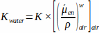
A dedicated software17 was used to calculate the photon energy spectrum in air with no phantom, and we used the NIST table18 to calculate the mean mass energy absorption coefficient.
In this work, we used a platform dedicated to small animal irradiation19; however, this platform can be used to irradiate other types of samples such as cells. The irradiation source is a Varian X-ray tube (NDI-225-22) having an inherent filtration of 0.8 mm of beryllium, a large focal sport size of 3 mm, a high voltage range of about 30 to 225 kV and a maximal intensity of 30 mA.
The parameters used for this study are reported in Table 1. We have chosen to show an example of the use of this protocol for cell irradiation in a T25 flask with 5 mL of cell culture media.
Half value layer
Table 2 reports the measurements performed to estimate the attenuator thickness needed to decrease the intensity of the beam by a factor of two. For this, 10 reference measurements were taken to estimate the average Mraw reading on the electrometer (in Coulombs), corrected by the temperature and pressure correction factor (KT,P).
Different thickness of attenuators were then tested to find the thickness that decreased the beam intensity by a factor of two. When this thickness was found, five measurements were taken to evaluate the average Mraw value corrected by KT,P.
For this configuration, a half value layer of 0.667 mm of copper was found. From the HVL measurement, we can calculate the effective energy of the beam, which is about 69 keV in our case.
Dose rate measurement
Before to these measurements, an EBT3 film was irradiated in order to determine the surface on which the irradiation field is homogeneous, allowing us to correctly place the cell container. This area is about 10 x 10 cm² excluding penumbra regions shown by dotted lines in Figure 2. Then, dose rate measurement was performed using a 31002 (equivalent to 31010) cylindrical ionization chamber calibrated in air kerma. For this configuration, with an open field irradiation field at 35 cm to the source in a T25 cell container placed on a carbon plate, the dose rate was about 0.626 Gy.min-1 in Kair.
To determine the exact dose on cells, the measured Kair was converted in water kerma. Figure 5 shows the X-rays energy spectrum obtained with dedicated software17. From this energy spectrum and the NIST table, we can convert the dose rate in Kair to Kwater, which was 0.659 Gy.min-1.
The overall uncertainty of the absolute dose rate measurement was about 3% at a 95% confidence level.
Cell culture media attenuation and scattering
For the quantification of cell culture media attenuation and scattering, dosimetry measurements with EBT3 radiochromic films were performed at room temperature. From the measurement with the ionization chamber, the dose rate was determined. Calibration films were then irradiated at the same position. EBT3 radiochromic films were calibrated between 0 and 3 Gy with 0.25 Gy steps between 0 and 1 Gy and 0.5 Gy steps between 1 and 3 Gy (nine dose points to construct the calibration curve) as shown in Figure 6. The dose points were fitted with a 4th-degree polynomial curve. The EBT3 films were then irradiated with and without the exact quantity of cell culture media inside the cell container to evaluate the attenuation and the scattering due to the cell culture media. For this configuration, the attenuation of the cell culture media was about 1.5%.
The overall uncertainty of the EBT3 film measurements was about 4% at a 95% confidence level.
Routine measurements
Before performing the cell irradiations, the dose rate was measured each time in the same container used for irradiation. Thus, we used the daily dose rate to estimate the irradiation time. If we closely follow the protocol and do not change any parameters, the HVL measurement and the attenuation due to the cell culture media do not need to be repeated. As an example, the table used for the daily measurement is given in Table 3.
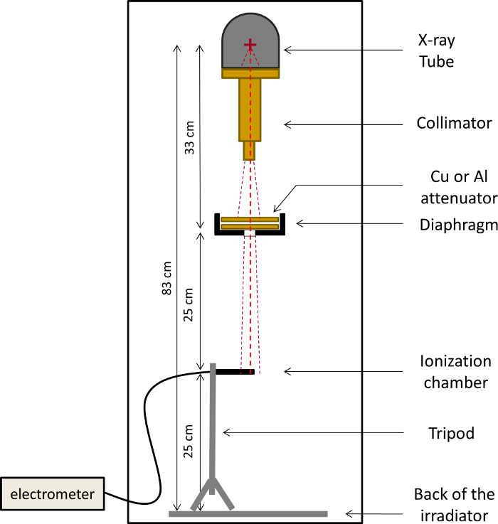
Figure 1: Scheme of the configuration take in place on the SARRP enclosure for HVL measurements. Please click here to view a larger version of this figure.
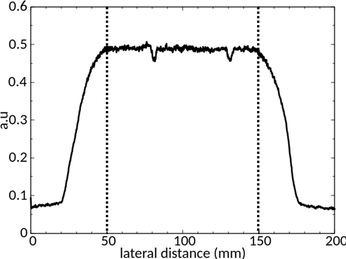
Figure 2: Evaluation of the irradiation field size. Dose profile obtained at 35 cm to the source without collimator. Dotted lines show the area considered for the irradiation. Please click here to view a larger version of this figure.
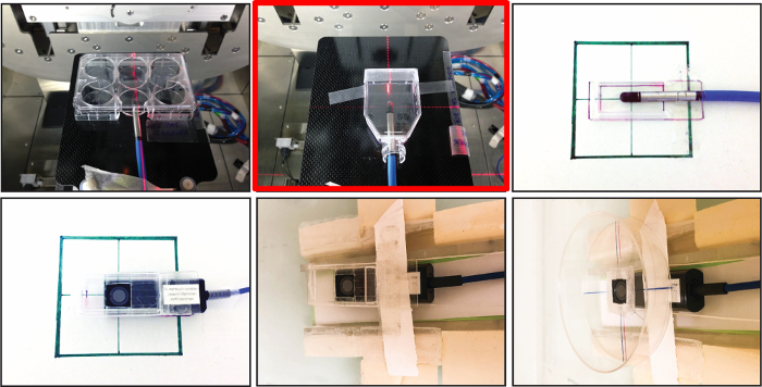
Figure 3: Photographs of cell containers with the ionization chamber for dose rate measurement. Upper part: example for measurement with a 31002 cylindrical ionization chamber. Lower part: example for measurement with a TM23342 ionization chamber. Please click here to view a larger version of this figure.
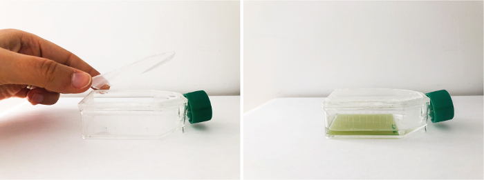
Figure 4: Photographs of the T25 used for the measurement of the cell culture media attenuation. The upper part of the T25 was cut out to be able to place the film inside the flask. Please click here to view a larger version of this figure.
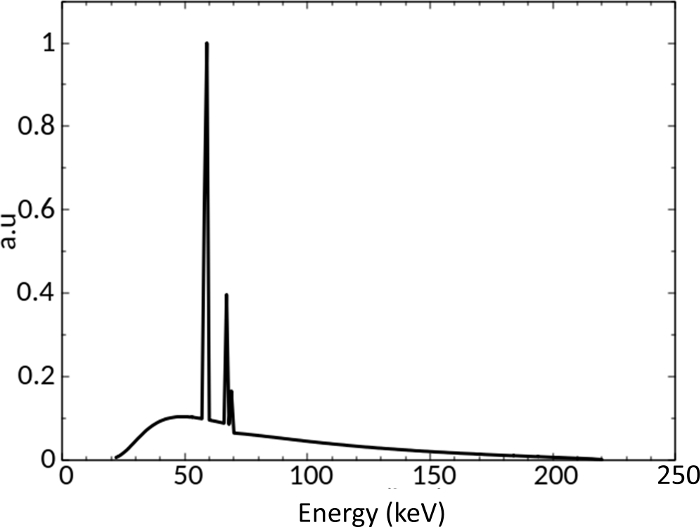
Figure 5: Simulated energy spectra for a 220 kV high voltage with 0.8 mm of Be and 0.15 mm of Cu filtrations17 . Please click here to view a larger version of this figure.
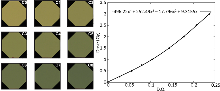
Figure 6: EBT3 films irradiated to construct the calibration curve and the corresponding calibration curve. Please click here to view a larger version of this figure.
| High voltage (kV) | 220 |
| Intensity (mA) | 3 |
| Filtrations (inherent and additional) | 0.8 mm of Be + 0.15 mm Cu |
| Half value layer (mm Cu) | Determined below |
| Effective energy (keV) | Determined below |
| Detector used | Cylindrical ionization chamber + EBT3 radiochromic films |
| Source sample distance | 35 cm |
| Irradiation field (shape, size, geometry) | Open field (no collimator), square, 20 x 20 cm |
| Dosimetry quantity | Kair and Kwater |
| Dosimetry method | As described on the protocol section |
| Cell container | T25 |
| Quantity of cell culture media | 5 ml |
| Dose rate (Gy/min) | Determined below |
Table 1: A List of the configuration parameters.
| Attenuator (mm Cu) | IC measure (nC) | Temperature (°C) | Pressure (hPa) | kT.P | IC measure corrected by kT.P (nC) | Corrected Mean value (nC) | ST deviation | Attenuation estimation (M / Mref) | |
| reference measurements (Mref) | 0 | 10.480 | 21.6 | 993.2 | 1.026 | 10.752 | 10.761 | 0.005 | – |
| 10.480 | 21.6 | 993.1 | 1.026 | 10.752 | |||||
| 10.490 | 21.6 | 993.1 | 1.026 | 10.763 | |||||
| 10.490 | 21.6 | 993.1 | 1.026 | 10.763 | |||||
| 10.490 | 21.6 | 993.2 | 1.026 | 10.763 | |||||
| 10.490 | 21.6 | 993.2 | 1.026 | 10.763 | |||||
| 10.490 | 21.6 | 993.1 | 1.026 | 10.763 | |||||
| 10.490 | 21.6 | 993.2 | 1.026 | 10.763 | |||||
| 10.490 | 21.6 | 993.2 | 1.026 | 10.763 | |||||
| 10.490 | 21.6 | 993.1 | 1.026 | 10.763 | |||||
| Finding of attenuatior thickness (M) | 0.514 | 5.840 | 21.7 | 993.2 | 1.026 | 5.992 | – | – | 0.557 |
| 0.564 | 5.651 | 21.7 | 993.2 | 1.026 | 5.798 | – | – | 0.539 | |
| 0.584 | 5.569 | 21.7 | 993.2 | 1.026 | 5.714 | – | – | 0.531 | |
| 0.604 | 5.491 | 21.7 | 993.2 | 1.026 | 5.634 | – | – | 0.524 | |
| 0.615 | 5.441 | 21.7 | 993.2 | 1.026 | 5.582 | – | – | 0.519 | |
| 0.627 | 5.380 | 21.7 | 993.2 | 1.026 | 5.520 | – | – | 0.513 | |
| 0.647 | 5.307 | 21.7 | 993.2 | 1.026 | 5.445 | – | – | 0.506 | |
| 0.667 | 5.240 | 21.8 | 993.2 | 1.026 | 5.376 | – | – | 0.500 | |
| Measurments with the right attenuator (M) | 0.667 | 5.231 | 21.8 | 993.4 | 1.026 | 5.368 | 5.373 | 0.003 | 0.499 |
| 0.667 | 5.236 | 21.8 | 993.1 | 1.026 | 5.375 | ||||
| 0.667 | 5.235 | 21.8 | 993.2 | 1.026 | 5.373 | ||||
| 0.667 | 5.236 | 21.8 | 993.2 | 1.026 | 5.374 | ||||
| 0.667 | 5.235 | 21.8 | 993.3 | 1.026 | 5.373 |
Table 2: Measurement for the Half Value Layer determination.
| IC measure (nC) | Temperature (°C) | Pressure (hPa) | kT.P | IC measure corrected by kT.P (nC) | Corrected Mean value by kT.P (nC) | ST deviation | Corrected mean value by all correction factors | Dose rate in air kerm (Gy/min) | Dose rate at cell level in Kwater (Gy/min) |
| 2.495 | 22.3 | 1001 | 1.020 | 2.545 | 2.546 | 0.001 | 2.536 | 0.626 | 0.659 |
| 2.496 | 22.3 | 1001 | 1.020 | 2.546 | |||||
| 2.497 | 22.3 | 1001 | 1.020 | 2.547 | |||||
| 2.498 | 22.3 | 1001 | 1.020 | 2.548 | |||||
| 2.496 | 22.3 | 1001 | 1.020 | 2.546 | |||||
| 2.495 | 22.3 | 1000.9 | 1.020 | 2.545 | |||||
| 2.494 | 22.3 | 1000.9 | 1.020 | 2.544 | |||||
| 2.495 | 22.3 | 1000.9 | 1.020 | 2.545 | |||||
| 2.496 | 22.3 | 1000.9 | 1.020 | 2.546 | |||||
| 2.496 | 22.3 | 1000.9 | 1.020 | 2.546 |
Table 3: Daily dose rate measurements for cell irradiation.
