1. Cantilever Chip Fabrication
Illustrated details of the described fabrication steps are provided in Figure 1.
- Place Silicon-On-Insulator (SOI) wafers in an oven and bake at 125 °C for 20 min to dehydrate them.
- Deposit a 1.5 µm thick layer of silicon oxide onto the handle layer of the dehydrated SOI wafer using a Plasma Enhanced Chemical Vapor Deposition (PECVD) tool.
- Place the wafer on the spin coater chuck with the device layer facing up. Ensure wafer is centered, dispense 2 ml of P20 primer on the center of the wafer, and spin at 3,000 rpm for 60 sec at an acceleration of 1,000 rpm/sec. P20 primer promotes the adhesion of photoresist to the device layer.
- While the wafer is still on the spin coater chuck, dispense 2 ml of S1818 photoresist on the center of the wafer, and spin at 3,000 rpm for 60 sec at an acceleration of 1,000 rpm/sec to obtain a 1.5 µm thick layer of photoresist.
- Place the wafer on a hot plate and perform a soft bake at 115 °C for 1 min.
- Perform a hard contact UV exposure using a photolithography contact mask aligner in order to transfer the pattern from the cantilever mask to the photoresist on the device layer. Calculate the exposure time based on exposure energy value of 125 mJ/cm2 for S1818 photoresist.
- Develop the photoresist by immersing the wafer in a 726 MIF photoresist developer for 1 min while gently shaking the wafer back and forth.
- Rinse the wafer with de-ionized (DI) water and dry it, preferably using a spin rinse dryer (SRD) tool.
- Remove the photoresist from the edge of the wafer (up to 5 mm from the edge) using a cotton swab dipped in acetone.
- Load the wafer in a Deep Reactive Ion Etch (DRIE) tool, with the photoresist side facing up, and run a recipe to etch the patterned silicon layer through the device layer. The buried oxide layer functions as an etch stop, so perform an etch with 50% to 100% more cycles than is expected to be necessary to ensure a complete etch.
- Place the wafer in a hot photoresist bath solution for 20 min to strip the photoresist. Transfer the wafer to a quick-dump-rinser (QDR) to rinse the wafer with DI water. Following the photoresist strip, load the wafer in a SRD tool to rinse and dry the wafer. Inspect the wafer under a microscope to ensure the cantilever pattern appears as expected.
- Deposit a 1 µm thick layer of un-doped silicon oxide on the device layer of the wafer using a PECVD tool. This oxide layer functions as a protective layer for the cantilevers during further processing steps.
- Place the wafer on the spin coater chuck with the handle layer facing up to begin processing of the back side of the wafer. Ensure wafer is centered, dispense 2 ml of P20 primer on the center of the wafer, and spin at 3,000 rpm for 60 sec at an acceleration of 1,000 rpm/sec.
- While the wafer is still on the spin coater chuck, dispense 2 ml of SPR220-4.5 photoresist onto the center of the wafer, and spin at 2,000 rpm for 45 sec at an acceleration of 1,000 rpm/sec to obtain a 6.5 µm thick layer of photoresist.
- Place the wafer on a proximity hot plate to perform a soft bake at 115 °C for 2 min.
- Using a photolithography contact aligner capable of front/back alignment, align the backside window mask to the front side cantilever pattern and perform a hard contact UV exposure in order to transfer the pattern from the backside window mask to the photoresist on the handle layer. Use an exposure time calculated based on exposure energy value of 480 mJ/cm2 for SPR220-4.5 photoresist.
- After UV exposure, let the wafers remain in a dark area for 30 min before the next processing step.
- Develop the photoresist by immersing the wafer in a 726 MIF photoresist developer for 2 min while gently shaking the wafer back and forth.
- Rinse the wafer with de-ionized (DI) water and dry it, preferably using a spin rinse dryer (SRD) tool.
- Place the wafers in an oven at 90 °C for 12 hr.
- Etch the silicon oxide layer on the backside of the wafer using an RIE system with fluorinated gases and a recipe for etching oxide. The patterned oxide on the backside of the wafer acts as an etch mask for further processing. Inspect the wafers under a microscope to ensure that the silicon oxide in the exposed window is completely etched.
- Remove the photoresist on the edge of the wafer (up to 5 mm from the edge) using a clean room swab dipped in acetone.
- Load the wafer in a DRIE tool with and run a recipe to etch the patterned handle layer to a depth of 500 µm with the buried oxide layer functioning as an etch stop. Split this etch into multiple runs to prevent excessive heating of the wafer, which causes inconsistent etching of the silicon. This etch step completely removes the silicon underneath the cantilevers.
- Perform a wet etching step using 25% dilute HF etchant, to strip the buried oxide layer below the cantilevers and the protective oxide layer on top of the cantilevers.
NOTE: This step releases the bottom surface of the silicon cantilevers and also opens a window underneath to provide an access to probe the cantilever with the laser. - Rinse the wafer using a series of DI water baths and carefully dry with nitrogen. Since the cantilevers are supported only at their bases, do not use forceful sprays of DI water or inert gas directly on the cantilevers.
- Cleave the individual chips from the wafer along the cleave lines produced during the handle layer etch step.
2. Cell Culture
- Prepare 13F coverslips according to previously published methods17.
NOTE: If 13F coverslips are not available, any hydrophobic surface with a contact angle above 95° can be used. - Sterilize cantilever chips and 13F coverslips in a 70% ethanol solution and allow to air dry in a flow hood.
- Place individual cantilever chips on top of 13F coverslips inside a standard 12 well plate.
- Coat the cantilevers with the biopolymer or surface modification optimized for the cell type being used according to the standard cell culture protocols.
- Re-suspend the cells in their specific growth medium to the desired concentration.
NOTE: This protocol will result in a substantial number of cells falling through the cantilever window and not adhering to the desired cantilever surface. Cell preparations should therefore be made 3-4x more concentrated than for standard coverslip preparations. For example, seeding of rat skeletal muscle satellite cells is typically carried out using a seeding density of 500 to 700 cells/square mm15,16, and are used with cantilever substrates at 2,000 cells/square mm. Optimization experiments should be carried out with new cell sources to ascertain an appropriate seeding density. - Pipette 200 μl of the cell suspension onto the cantilever chip surface, ensuring the bubble of medium covers the cantilever windows entirely. If the medium wicks through the window and doesn’t form a static bubble on top of the cantilevers replace the 13F coverslip and reattempt the plating.
- Transfer the plate containing the chips to an incubator and allow the cells to adhere for at least 1 hr (preferably 2-3 hr).
- After this plating period, use sterile forceps to transfer the chip to a clean well, without a 13F coverslip, and top up the culture with 1 ml of growth medium.
- Return the plate to the incubator.
- Maintain cells according to their standard protocol for in vitro maintenance on coverslips. For skeletal muscle cells, a switch of medium composition to induce myotube formation once cells become confluent will be necessary.
3. Setup of Hardware and Software for Cantilever Deflection Analysis
- Place a heated culture dish into the stage of an upright electrophysiology microscope.
- Add 3 ml of the feeding medium the cells are currently suspended in (+ 10 mM HEPES) to the heated microscope stage.
- Mount stainless steel electrodes on the inside of the heated culture dish at a separation distance of 15 mm and connect them to a pulse generator, capable of producing field stimulation pulses of varying intensity, frequency, and waveform, to allow the system to produce field stimulation of cells when appropriate.
- Bolt a Helium-Neon laser, mounted on XY translational stages, to the underside of the microscope table and adjust it so that the laser beam is directed through the base of the heated culture dish at a 30° angle relative to the plane of the cantilever.
- Bolt a quadrant photo-detector module, mounted on XY translational stages, to the underside of the microscope stage and adjust the position so that the reflected laser beam lands in the center of the 4 quadrants. Figure 2 provides an overview of the hardware set up necessary for implementing the described protocol.
- Write a software program to control the linear actuators that scan across the cantilevers. Write the software program with reference to the flow chart provided in Figure 3. The graphical interface programmed for use with this system is provided in Figure 4.
4. Recording Cantilever Deflection Data
- Turn on the cantilever analysis hardware and associated software.
- Insert the heated stage thermistor into the medium and wait for it to read 37 °C.
- Insert the cantilever chip into the stage with the cantilevers oriented toward the right hand side of the stage.
- Turn on the microscope light source.
- Focus the microscope to bring the edges of the cantilevers into view and use the laser/photo-detector control software to position the laser beam on the tip of cantilever 1. NOTE: Assuming the cantilevers are oriented to the right of the stage, cantilever 1 is the one positioned in the top left of the array and numbers run down to 16 in the bottom left. Cantilever 17 is in the top right position and runs to 32 in the bottom right (Figure 5A).
- Press “play” on the recording software.
- Position the photo-detector so that the signal reads “0” in both x and y frames by adjusting the stepper motors controlling the photo-detector.
- Set cantilever 1 position in the laser/photo-detector control software (Figure 4).
- Move the laser to the tip of cantilever 16, repeat step 4.7., and set cantilever 16 position in the laser/photo-detector control software.
- Move the laser to the tip of cantilever 32, repeat step 4.7., and set cantilever 32 position in the laser/photo-detector control software.
- Move the laser to the tip of cantilever 17, repeat step 4.7., and set cantilever 17 position in the laser/photo-detector control software.
- Turn off the microscope light source and the overhead light in the laboratory.
- Press “record” on the recording software.
- Set the pulse generator hardware to 40 msec, 5 V pulses at a frequency of 1 Hz, and turn the machine on.
NOTE: Optionally, employ optimized stimulation protocols for specific cell sources at this point, the stated settings are guidelines based on collected data using human and rodent cell sources12,13,15,16. - Using the laser/photo-detector control software, set the hardware to scan across the 32 cantilever array, stopping for 5 sec at each one.
- When the scan of the 32 cantilevers is complete, turn off the stimulator, then stop the recording software and bring up the data file.
- Examine the recorded trace from each cantilever for evidence of contractile activity. Make a note of each cantilever with positive responses. A contraction is defined as a peak if the deflection is at least 0.1 V above the baseline.
- Remove any non-responsive cantilevers from the scan protocol on the laser/photo-detector control software.
- The active cantilevers can then be rescanned without stimulation in order to get a reading of the cell’s spontaneous contractile activity.
- Run scans with or without broad field electrical stimulation, following addition of a therapeutic compound to the medium in order to observe its effect on the functional output of the cultured cells.
- Carry out fatigue assessments by electrically stimulating the cells for extended periods and scanning levels of contractility to measure how long it takes for peak force to drop below a specific threshold.
- In experiments where motor neurons are maintained in co-culture with muscle, measure neuromuscular junction formation through treatment of motoneuron-myotube cantilever co-cultures with a neuronal stimulant (such as glutamate) or synaptic inhibitor (e.g., D-tubocurarine) and scanning for increases and decreases in spontaneous activity respectively16.
- Perform specific scans as dictated by the needs of the planned experiments.
5. Analysis of Cantilever Deflection Data
- Use modified Stoney’s equations15 (detailed below) to convert raw cantilever deflection data (in Volts) into a readout of stress in the cell layer or myotube (in Pascals), and a direct measurement of cellular contractile force (in nano-Newtons) :
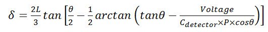 Equation 1
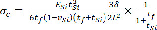 Equation 2
 - Where δ = cantilever tip deflection and stress produced by the myotube, σc = stress produced by the myotube, assuming a uniform thick film the full width of the cantilever, Cdetector = the system-specific coefficient relating voltage to laser position on the photo-detector, θ = the angle of the laser and detector relative to the plane of the cantilever, ESi = the elastic modulus of silicon, tSi =the thicknesses of the cantilever, tf= myotube thickness, vSi =poison’s ratio of silicon, L = cantilever length, P = path length of laser from cantilever tip to detector, and wSi = the width of the cantilever. A schematic explaining the terms used in these equations is provided in Figure 6.
- Assuming the myotube is a uniform film, the force in the myotube is equal to the force in the film, leading to Equation 3, by equating the calculation of force from stress and the assumed cell cross sectional area that was used for the application of Stoney’s equation.
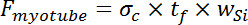 Equation 3
 - Following functional data collection, fix cantilever chips for immunocytochemical analysis or utilize cells for protein or DNA analysis using standard techniques.
- Optionally, return the cells to the incubator instead of preparing for molecular analysis in order to reassess functional performance at a later time-point.
Successful culture of contractile cells on cantilevers is a relatively straightforward procedure, utilizing standard cell culture techniques (Figure 5). The percentage of cantilevers supporting contracting cells will vary depending on cell type being examined and specific culture technique employed. Using primary embryonic cells derived from rat hind limbs, contractile activity was detected on 12% of cantilevers examined (n = 4). Analysis of contractile function using the laser and photo-detector system described provides accurate real-time data pertaining to the functional maturity of the seeded cells. Use of standard electrophysiological software can then be used to analyze the raw data, facilitating calculation of relevant functional properties, such as peak force, time to peak force, and time to half relaxation, as illustrated in Figure 7. Subsequent data collection from cultures treated with therapeutic compounds allows for comparison of functional properties with and without drug addition, thereby enabling assessment of compound activity and subsequent prediction of in vivo responses. Furthermore, extended stimulation protocols provide the means to assess rates of fatigue in cultured cells, thus broadening the level of physiological data obtainable from this system (Figure 8).
The cantilever culture can be modified to include motor neurons in the culture system with skeletal muscle myotubes16, so as to allow assessment of neuromuscular synapse formation in vitro (Figure 9). In such cultures, rates of spontaneous contractile activity are compared to rates of contraction in response to treatment with a neuron-specific stimulant, such as glutamate. Any observed glutamate induced increases in contraction rates suggest the activation of cultured neurons, leading to acetylcholine release and subsequent myotube activation. Treatment with synaptic inhibitors, such as the acetylcholine receptor blocker D-tubocurarine, leading to cessation of glutamate induced activity provide further evidence for the presence of functional neuromuscular synapses in these cultures16.
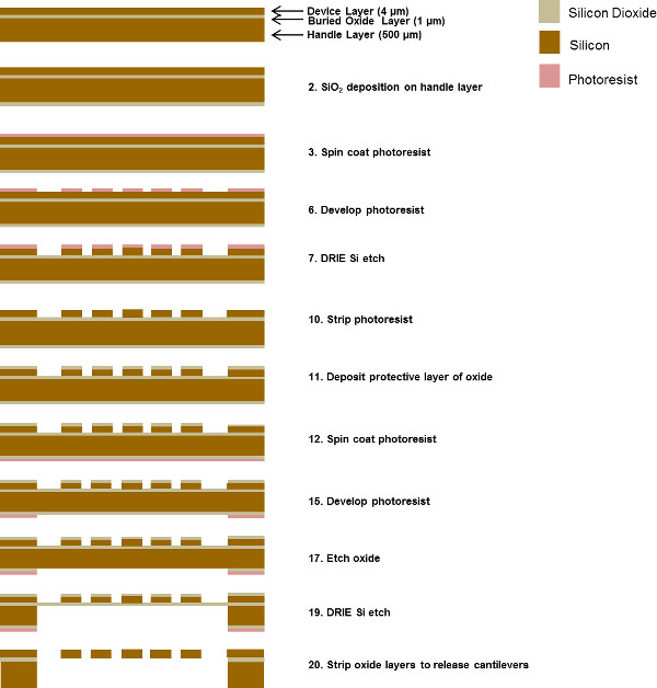
Figure 1. Schematic detailing cantilever fabrication process flow. The numbers listed in the flow diagram correlate to protocol steps in the methods section titled “Cantilever chip fabrication.” Please click here to view a larger version of this figure.
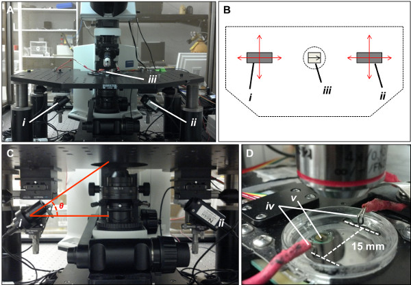
Figure 2. Hardware details of the laser/photo-detector system used to assess cellular contraction on cantilevers. (A) Photograph of the modified electrophysiological microscope used for cantilever assessment. The laser (i) and photo-detector (ii) are mounted beneath the stage on XY translational stages. A transparent culture dish is mounted on the stage (iii), which allows laser passage to the cantilever array through the underside of the stage. (B) Schematic “top-down” perspective of the microscope stage. XY translational stages allow movement of the laser and photo-detector in both X and Y planes (red arrows), facilitating movement of the laser to interrogate each cantilever in an array. Cantilever chips (iii) should be placed into the stage with the cantilevers facing toward the right of the stage in order for the system to operate correctly. (C) Close up photograph of the laser (i) and photo-detector (ii) mounted beneath the microscope stage. The laser is positioned at a 30° angle relative to the plane of the cantilever chip (θ). (D) Close up photograph of the culture dish. Broad-field electrical stimulation is applied by means of a pair of silver electrodes positioned 15 mm apart (iv). A heating element (v) attached to the underside of the dish is used to maintain the culture at 37 °C during analysis. Temperature control is dynamic, and regulated by means of a thermistor placed in the medium (not shown). Please click here to view a larger version of this figure.
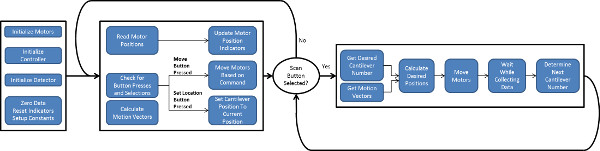
Figure 3. Flow chart of logic underlying software to control scanning of the laser and photo-detector. Two software loops control motion: a main loop for user input and a loop that controls the scanning motion. Setup is performed while in the main loop, followed by activation of the second loop for medium- to high-throughput data collection. Please click here to view a larger version of this figure.
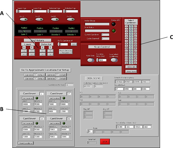
Figure 4. Graphical user interface of software used to control laser and photo-detector positions during cantilever assessment. (A) Buttons to manually control laser and photo-detector positions in both X and Y planes. (B) Controls for manually setting the positions of the 4 corner cantilevers (1, 16, 17, and 32), thereby allowing the software to extrapolate the positions of the remaining cantilevers in the array. (C) Controls allowing users to select which cantilevers to include in each scan. Please click here to view a larger version of this figure.
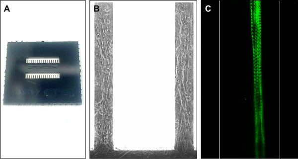
Figure 5. Images of a custom built cantilever chip for use in this system, and representative images of cells maintained on similar surfaces. (A) Photograph of a single, custom built cantilever chip. Each chip contains 32 cantilevers arranged in 2 rows of 16. Cantilever 1 is positioned in the bottom left of the image and cantilever 32 in the top right. Cantilever chips are 15 x 15 mm2. (B) Phase-contrast image of primary rat skeletal muscle cells grown on cantilevers. Each cantilever is 750 μm long, 100 μm wide and 4 μm thick. (C) Immunocytochemical stain of a primary rat myotube maintained on a cantilever. Cells were stained using an antibody probe for Myosin Heavy Chain. Note the striated appearance of the cultured fiber, indicating maturation of the contractile machinery. Cantilever edges have been artificially highlighted in this image to provide an indication of scale. Please click here to view a larger version of this figure.
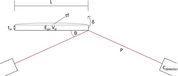
Figure 6. Schematic illustrating the terms used in Stoney’s equations for deriving force produced by myotubes on cantilevers. δ = cantilever tip deflection and stress produced by the myotube, Cdetector = the system-specific coefficient relating voltage to laser position on the photo-detector, θ = the angle of the laser and detector relative to the plane of the cantilever, ESi = the elastic modulus of silicon, tSi = the thicknesses of the cantilever, tf = myotube thickness, vSi = poison’s ratio of silicon, L = cantilever length, and P = path length of laser from cantilever tip to detector. Please click here to view a larger version of this figure.
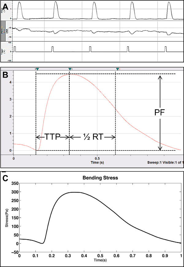
Figure 7. Representative raw data and analysis of contractile form using the cantilever system described. (A) Example of a raw data trace from the broad-field electrical stimulation of primary rat myotubes on cantilevers. Top trace = laser deflection (in Volts) in the x-axis, indicating lengthwise strain on the cantilever. Middle trace = laser deflection (in Volts) in the y-axis, indicating torsional strain across the cantilever. Bottom trace = Indication of the temporal position of electrical pulses used to elicit myotube contraction in this system. (B) Using standard electrophysiology software, it is possible to measure peak force (PF), time to peak force (TTP) and time to half relaxation (1/2 RT) from the collected raw data. (C) Collated contraction data (n = 11) from primary rat skeletal muscle myotubes. Application of a modified Stoney’s equation allows calculation of cantilever stress from raw data readings in Volts. From this data, direct calculation of force (in Newtons) can also be generated. Published data reprinted with permission13. Please click here to view a larger version of this figure.
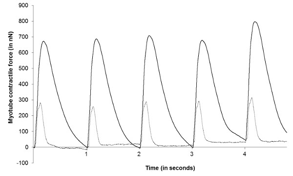
Figure 8. Representative data demonstrating analysis of skeletal muscle fatigue in cantilever cultures. Raw data (in Volts) was converted to a measurement of myotube force (in nano-Newtons) and re-plotted. Data illustrates magnitude of myotube contractions on cantilevers in response to 1 Hz broad-field electrical pulses after 0 min (black trace) and 120 min (grey trace) of continuous stimulation. Please click here to view a larger version of this figure.
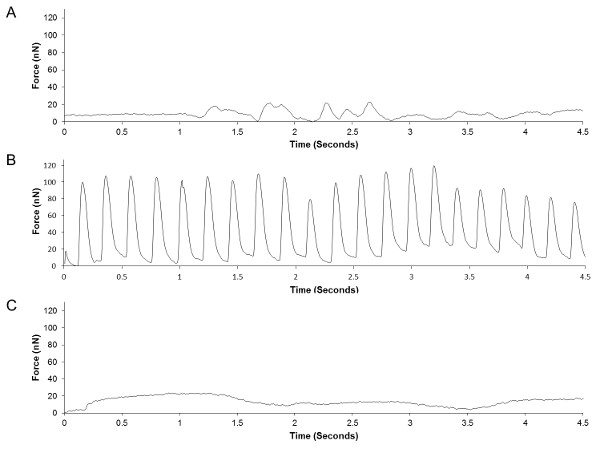
Figure 9. Representative traces from the analysis of a skeletal muscle-motoneuron co-culture maintained on cantilevers, demonstrating the functional effects of motoneuron stimulation with and without addition of a neuromuscular blocker. Raw data (in Volts) was converted to a measurement of myotube force (in nano-Newtons) and re-plotted. (A) Measurement of spontaneous contractions by the cultured myotubes without neuronal stimulation. (B) Measurement of myotube contraction following neuronal stimulation via the addition of 200 μM glutamate. (C) Measurement of myotube contraction following glutamate and 12.5 μM D-tubocurarine treatment. Published data reprinted with permission16. Please click here to view a larger version of this figure.
The following tables list the specific reagents used to culture cells in the validation experiments described, as well as the equipment necessary to perform the cantilever assessment. Please note that culture reagents used are not necessary and this system should be easily integrated with the culture protocols of any lab maintaining contractile cells in vitro. The listed reagents are provided should investigators wish to repeat the specific experimental results described.
