여기에서 우리는 자료를 추정 총 내부 반사와 결합 된 광 음향 효과를 사용하여 광학 특성을 표면에 프로토콜을 제시한다. 이 기술 산장 기반 photoacoustics 그들의 광학 특성 물질 '두께 벌크 박막의 굴절률을 측정하는 계측 광 음향 시스템을 구축하고 탐색하는데 사용될 수있다.
Here, we present a protocol to estimate material and surface optical properties using the photoacoustic effect combined with total internal reflection. Optical property evaluation of thin films and the surfaces of bulk materials is an important step in understanding new optical material systems and their applications. The method presented can estimate thickness, refractive index, and use absorptive properties of materials for detection. This metrology system uses evanescent field-based photoacoustics (EFPA), a field of research based upon the interaction of an evanescent field with the photoacoustic effect. This interaction and its resulting family of techniques allow the technique to probe optical properties within a few hundred nanometers of the sample surface. This optical near field allows for the highly accurate estimation of material properties on the same scale as the field itself such as refractive index and film thickness. With the use of EFPA and its sub techniques such as total internal reflection photoacoustic spectroscopy (TIRPAS) and optical tunneling photoacoustic spectroscopy (OTPAS), it is possible to evaluate a material at the nanoscale in a consolidated instrument without the need for many instruments and experiments that may be cost prohibitive.
렌즈에 반사 방지 코팅을 포함한 광학 장치의 호스트 박막 재료의 생성에 새로운 통찰력을 제공 한 1,3,4,6,7,10,13-16 광학 재료의 이해를 발전 높은 소광비 광 필터 및 높은 흡수 슬래브 도파로 (17). 이러한 진보의 반복 개선에 도움 같은 타원 4,6,18, 접촉각 측정, 원자력 현미경 7,11,19 및 스캔 / 투과형 전자 현미경 등 다양한 특성화 기술의 사용없이 불가능했을 직접 조치 또는 기본 광학 재료 특성의 간접적 인 추정치를 제공함으로써 이러한 기술. 재료는 직접 기능과 광학 애플리케이션에서의 사용에 영향을 미치는 입사 광자와 상호 작용하는 방법 등의 굴절률과 같은 특성, 적용했다. 그러나, 이들 기술들 각각은 한계가있다 resolu 관련능은, 샘플 준비, 비용, 복잡성, 각각 완전히 물질을 특성화하는 데 필요한 데이터의 서브 세트를 생성한다. 즉,이 산장 기반 photoacoustics (EFPA) 5,6,15,18,20-49 알려진 기술의 새로운 세트도 1에 도시 된 바와 같이, 상기되는 통합에 나노 크기 물질의 특성을 추정 할 가능성을 가지고 실험의 집합입니다. EFPA 전반사 광 음향 분광학 (TIRPAS) 23,25,26,33-35,43-45 광 음향 분광학 / 전반사 광 음향 분광 굴절계 (PAS / TIRPAS 굴절계) (18), 광 터널, 광 음향의 하위 기술을 포함 분광기 (OTPAS) 6, 벌크 및 박막의 굴절율, 막 두께를 추정하기 위해뿐만 아니라 프리즘 / 샘플 또는 기판 / 샘플 계면에서 흡수 물질을 검출하기 위해 사용되어왔다.
EFPA 메커니즘을 이해하기 위해, 하나의제 광의 초단 (<마이크로 초)의 펄스의 흡수 (도 1) 다음 발색단의 급속한 열 탄성 팽창에 의해 초음파 압력 파동의 발생을 의미 광 음향 분광학 (PAS)의 개념을 이해한다. 이 논문에 기술 된 광 음향 효과에 대한 이론 및 수학적 프레임 워크는 여기에 50-59를 얻을 수있다. 압력의 변화는 생성 된 초음파 트랜스 듀서 또는 마이크로폰에 의해 검출 될 수있다. 원래 알렉산더 그레이엄 벨의 photophone의 발명으로 1880 년에 발견 된 광 음향 효과는, 때문에 레이저와 마이크 기술의 발전으로 1970 년대 초에 "재발견", 결국 박막에 생물 의학 이미징에서 틈새 응용 프로그램을 채우기 위해 실용화되었다 재료의 비파괴 검사에 대한 분석.이 효과는 수학적 일차원 파동 방정식에있어서, 상기 제 설명 될 수 1,53-57,59-82전자 웨이브는 누구의 압력 (p)를 모두 위치 (x)와 시간 (t)에 따라 다릅니다 간단한 음향 소스입니다 :
양식 (64)의 간단한 음향 소스를위한 솔루션
P는 압력, 여기서 Γ는 H 0은 조사량 αv (S) 2 / C α 볼륨 열팽창 계수 P는 V (S)는 배지 중 음속이며, C P가 정압 열용량이다 = 레이저 빔, C는 흥분 매체 소리의 속도이고, X는 길이이고, t는 시간이다. 얻어진 음향 파의 크기 w는 재료의 광 흡수 계수에 직접 의존을 μHICH는 다시 그것의 초기 광 강도의 1 / K로 감쇠 할 때까지 광이 이동하는 거리의 측정은 광 투과 깊이, δ의 역이다. 식 (1) 일차원 평면파 소스에 대한 일반 식이지만, 일반적인 흡수 입체적 구형 파를 방출한다. 수학적 설명을 넘어 인해 자연적으로 존재하는 발색단 헤모글로빈에 의한 큰 광 흡수에 이러한 현미경, 단층 촬영, 높은 감도를 갖는 광 음향 효과로 인해 심지어 분자 영상과 음향 효과 (54) 스팬 많은 영상 방식의 응용 프로그램. 광 음향 효과의 다른 응용 프로그램도 다양한 박막 특성 15,16,20,21,24,26-32,36-39,41,42,56,83,84의 추정을 포함한다. 그러나 PAS 특정 한계를 가지고있다 : (1) 광범위한 광 투과 깊이는 표면에서 근접장 광학 특성을 검사하는 기능을 제거 (2)를방출 된 음향 에너지를 캡처의 효율성으로 인해 구형 멀리 검출기로부터 에너지의 대부분의 전파 (3) 샘플을 고려 파장 정권에서 발색단을 포함해야합니다으로 낮다.
산장 기반 기술과 결합 될 때, 그러나, 이러한 제한 사항의 많은 개선 될 수있다. 빛의 빔이 내부 전반사 (TIR)를 겪는 경우도 광섬유 도파로가 계산 및 통신 애플리케이션을위한 조명 큰 거리 (km)를 안내 할 수 있습니다 효과 스넬의 법칙에 의해 설명 된대로 산장이 발생합니다. 실제 응용에서, 산장 감쇠 총 반사 분광법 (ATR)을 포함한 특성 및 이미징 기술의 다양한 사용된다. 이미징 관심 샘플에 제 수백 나노 미터 이내에 의한 광 가둠을 높은 콘트라스트로 얻을 수있다. 소멸 필드는 exponentiall의 형태를 취한다수학 식 3 및 4에 도시 된 바와 같이 파장 정도의 통상적 인 광 투과 깊이를 외부 매체에 연장 Y 감쇠 필드 (보통 ~ 500 nm 이하)를 사용된다.
I 프리즘 / 샘플 인터페이스에서 위치를 z %의 광 강도이고, I 0 계면 %의 초기 광 강도이며, Z는 나노 미터의 거리이고, δ P는 수학 식에 나타낸 바와 같이, 광 투과 깊이 같은 작은 광학 침투 깊이와 4. 소멸 필드는 두 물질의 인터페이스에 매우 근접, 잘 광학 및 음향 회절 한계 아래의 환경과 상호 작용 할 수있다. 이 범위 내에서 물질이나 입자의 광학 특성은, 방법 (3)의 종류에 의해 검출 될 수있는 상호 작용의 생성, 변경 필드를 교란하거나 수도5,6,10,15,17,18,21,23,25-27,29-47,84-95.
소산 기술은 PAS와 혼합 될 때, 생성되는 광 음향 파형이도 1에 도시 된 바와 같이 기초 photoacoustics는 기술 (EFPA) 패밀리. 패밀리 포함 소멸 필드를 생성 소멸 필드와 상호 작용하는 물질 또는 입자를 특성화하는데 사용될 수있다 하지만, 전반사 광 음향 분광학 (TIRPAS), 광 터널, 광 음향 분광학 (OTPAS) 및 표면 플라즈몬 공명 광 음향 분광학 (SPRPAS)에 한정되지 않는다. 관심있는 독자는 TIRPAS 5,6,18,23,25,26,33-35,43-47, PAS / TIRPAS의 굴절계 (18)에 사용되는 방정식의 유도를 위해 다음 참조를 참조하고, OTPAS 6한다. 각각의 경우에, 광 음향 효과는 프리즘을 통해 간단한 투과율 상이한 여기 메커니즘을 통해 생성된다; 예를 들어, TIRPAS에서 빛이 순간적이며SPRPAS에서 음원의 기본 모드 인 표면 플라즈몬의 흡수를 통해 대신 반면 (샘플 재료 자체 또는 샘플 내의 게스트 분자를 포함 할 수있다)가 발색단에 프리즘 / 기판 / 샘플 인터페이스를 통해 연결된 보조 EM 파 소멸 필드의 에너지가 상기 프리즘 표면 상에 증착 된 금속층의 전자 구름에 전송할 때 생성. 기술의 가족은 원래 Hinoue 등.에 의해 1980 년대 초반에 발명 및 T. 이나가키 등에 의해에 개선. SPRPAS의 발명,하지만 인해 광원 및 사용 가능한 탐지 장비의 기술적 한계에 거의 개발을 보았다 . (: YAG nd)이 레이저 최근 이전 조사 감도 및 유틸리티 현대 폴리 불화 비닐 리덴 (PVDF), 초음파 탐지기 Q- 스위치 네오디뮴 도핑 된 이트륨 알루미늄 가넷 가능 증가 된 것으로 나타났다. 특히, 노스 다코타 나노초 – 펄스 : YAG레이저는 소재와 인터페이스 5,6,15,18,21-29,31-47,84의 다양한 광학 특성을 평가하기위한 유용한 도구가 될 EFPA 기술을 가능하게 피크 전력의 106 배의 증가를 초래 96. 또한, 이전의 연구는 또한 인해 비교적 큰 침투 깊이 53,55,57,59 전통적인 광 음향 분광법 (PAS) 기술로 달성 이전에 결코 계면에서 물질에 대한 구성 정보를 결정하기 위해 이러한 기술의 능력을 보여 주었다 61,62,69,73,75,80,81.
이 기능은 OTPAS 기술에서 다음 프로토콜에 표시됩니다; 그러나,보다 근본적인 수준에서 세 가지 방법은 각 기술의 능력을 결정하는 다른 결정적인 식에 의존한다. 예를 들어, TIRPAS, 소멸 필드의 광 투과 깊이, δ 'P에서 주로 생성 된 음향을 구동흡수 샘플 신호 강도를,에 의해 설명된다 :
λ 1 프리즘 매체를 통해 이동하는 광의 파장과 관계 λ에 의해 정의된다 λ = 1 / N, 1 N (1)이 프리즘 재료의 굴절률이고. 또한, θ는 자극의 각도를 지칭하며, N (21)는 각 매체의 굴절률의 비율을 의미하고, N이 샘플 재료의 굴절률이고 N 21 = N 2 / N (1)에 의해 정의된다. 광 투과 깊이가 클수록, 더 많은 물질을 조사한다. 광 음향 효과, 광 침투 깊이 더 큰, 더 많은 물질은 더 큰 음향 신호로 이어지는 음향 파를 생성 할 수 있습니다 여기되고있다.
<pTIRPAS 달리 클래스 = "jove_content"> 그러나, PAS에 / TIRPAS은 기본 방정식은 스넬의 법칙이다 굴절계 :N (1)이 프리즘의 굴절율이고, θ 1 프리즘 / 샘플 경계면에서의 입사각이고, n은 2 시료의 굴절률이며, θ (2)는 제 통해 굴절되는 빛의 각도 매질. 물질의 굴절률을 추정하는 감도를 주로 θ 1은 소 산장을 발생하는 임계각 죄 θ (2) = 1 이상으로 될 때 달성되는 총 내부 반사 θ (1)의 추정의 정확도에 의해 구동되고 따라서, 식 (5)는 N 2 = n은 1 sinθ 1로 줄일 수 있습니다. (참고 : θ 1 =θ 수치 유도체 (P 피크 광 음향 신호의 전압과 θ의 피크 DP / dθ는 광 음향 신호의 샘플 광의 입사각)가되는 각도를 알면) 임계가있는 로컬 최소값 허용 사용자가 N 2 해결하고, 따라서도 1에 도시 된 바와 같이 샘플의 벌크 굴절율을 추정 할 수 있도록 한 θ의 추정.
마지막 OTPAS, 다음 식에 의해 피크 전압 음향 피크 %의 광 전송에 관한 것이다 :
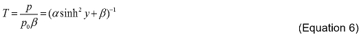
T는 비율 광전송이고, p는 그 위에 막을 갖는 기판의 각 스펙트럼에 의해 생성 된 피크 – 투 – 피크 전압이며, P 0 각도 스펙트럼 O에 의해 생성 된 피크 – 투 – 피크 전압이며FA 기판, β 프리즘 침지 오일의 굴절률에 기초하여 상기 결합 상수이며, α는 감쇠 계수이고, 두께와 산장 내의 샘플 필름의 굴절률을 포함하는 요소이다. 이 기법의 감도를 두께 및 굴절율이 각 스펙트럼에 입사 각 각도 음향 신호 세기, P 및 P 0과 피크 정점의 추정 정밀도에 의해 구동된다. 이는 β 직접 프리즘 침지 오일의 굴절률에 기초하여 계산 될 수 있음을 도시하고있다; 결과적으로, 각 입사 각도 광전송을 계산하고 통계적 커브 피팅 분석을 통해 필름의 굴절률 및 두께에 대한 추정치를 추출하는 간단한 작업이다. 관심있는 독자는 골드 슈미트 등을 참조해야합니다. 자세한 내용은. 5,6
티그 시스템은 두께 박막 굴절률 벌크 굴절율을 추정 및 검출을위한 광 흡수를 통해 음향 신호를 생성 할 수있는 광 음향 기반 시스템 EFPA. 시스템은 레이저로 구성되고, 광 열차 프리즘 / 샘플로하고, 레이저 에너지 측정면에 광을 안내한다. 도 2에 도시 된 바와 같이, 레이저 에너지 측정면은 입사 레이저 에너지의 광 음향 신호를 정규화하기 위해 사용된다. EFPA 시스템 스테퍼 모터 드라이버에 의해 구동되는 PAS / TIRPAS의 굴절계 및 OTPAS 내의 각 스펙트럼에 대한 / 샘플 프리즘을 회전 . 이 시스템은 디지털 수집 카드를 통해 데이터를 획득하고, 집에서 프로그램을 통해 사용자 인터페이스와 자동 단계 제어를 제공한다.
The use of devices for the characterization of materials at the nanoscale will undoubtedly continue far into the future in order to produce new materials and combinations of materials to solve difficult and costly societal problems. Many methods such as ellipsometry, atomic force microscopy (AFM), and traditional photoacoustics are currently used to evaluate material properties at the nanoscale despite their inherent limitations due to few alternatives. EFPA shows promise as a consolidated set of techniques that can push beyond the typical limitations of the photoacoustic effect to provide a single instrument to characterize materials at the nanoscale.
The protocol described herein and its associated sub-techniques have the capability to estimate both bulk and thin film refractive indices of a material, film thickness, and have detection capabilities for a variety of biosensing applications. OTPAS specifically has the advantage that it can estimate the thickness and refractive index of nanometer scale films despite the fact that the films themselves do not contain inherently absorbing pigmentation. EFPA as a consolidated set of techniques has a few advantages over techniques such as ellipsometry, atomic force microscopy, and the traditional photoacoustic effect. The first advantage is that EFPA is comparatively inexpensive to set up. A typical EFPA setup can estimate refractive index from both the bulk and surface, can estimate thickness, and can probe absorbing materials and will cost around $5,000 to set up. In contrast, AFM setups cost around $50,000 and cannot estimate optical properties. Secondly, EFPA can estimate these properties within a few minutes without complex interaction such as in ellipsometry where input parameter error can cause differences in results. Finally, EFPA, when compared to the traditional photoacoustic effect, has axial resolution 100X smaller as it can estimate thickness of 200 nm films6 whereas the traditional photoacoustic effect is limited to 7,500 nanometers when using similar lasers and setup82. Conveniently, almost every material has independent and differing surface and bulk refractive index properties as well as absorptive properties, which collectively make for functional differences in their use in optical research systems.
Critical steps within the protocol come down to three primary considerations. First, optical coupling of the sample, whether that be a liquid or a film, is crucial to obtain reliable and repeatable results. Air bubbles within the immersion oil or sample will lead to inaccurate characterization of the thickness, refractive index, and in some cases a complete lack of sensitivity of the transducer to the excited sample owing to the inability of ultrasound to adequately pass through a liquid/air interface due to vastly differing acoustic impedance values. Second, with regard to OTPAS, a sample that is homogeneously thick in the area irradiated by the laser beam in order to provide consistent thickness values during scanning since as of yet EFPA cannot determine thickness differences within the area of excitation. Finally, again with regard to OTPAS, the sample film must be transparent to the wavelength being used. This is a fundamental assumption made in the mathematical equations that describe how OTPAS finds thickness and refractive index values. If absorption is substantial enough that more than 1% of the incident light is absorbed by the film, characterization will not match the real thickness and refractive index values of the film.
Modifications to the EFPA technique can be made with relative ease and other types of components can be substituted in for more effective scans or functionality. The only major issues that have to be addressed when building an EFPA system are the following. First, it is crucial to have a method of automatically rotating a prism mount and acquiring acoustic signals at small (0.05 degree) increments. Second, having a nanosecond pulse width or shorter laser system to excite samples using the photoacoustic effect. Third, having a graphical user interface or program to acquire the data to do mathematical curve fitting and numerical derivatives for estimating thickness and bulk/thin film refractive index.
There are three fundamental limitations to EFPA. The first is that in order to find the bulk refractive index, thin film refractive index, thickness, or detect materials using TIRPAS, the sample must have a refractive index that is less than that of the prism or substrate it is in contact with so that total internal reflection can occur which is the basis of all three of these techniques. The second limitation is that EFPA currently requires physical contact in order to estimate thickness, refractive index, and for detection of properties. The final limitation is that OTPAS, a sub-technique of EFPA, currently requires optically transparent materials to estimate thickness and refractive index of the thin film of interest.
This type of consolidated instrument could find many applications in characterization environments including research cores and industrial environments. Future work regarding EFPA techniques is focused on the improvement of the refractive index accuracy through improvements in instrumentation and translational/rotational stages. Additional advancements will focus around the improvement of signal-to-noise ratio for the detection of smaller quantities of absorbing materials, so as to characterize weakly absorbing materials, as are found most commonly in biological systems.
The authors have nothing to disclose.
이 프로젝트는 국립 과학 재단 (National Science Foundation) Brige의 상 (1221019)에 의해 투자되었다.
100 mm plano convex lens | Thorlabs | LA1509 | Plano convex lens for beam expander |
-30 mm plano concave lens | Thorlabs | LC2679 | Plano concave lens for beam expander |
10 MHz Ultrasonic transducers | Harisonic | I31006T | Ultrasonic sensors used for photoacoustic detection, both for laser energy measurement and for OTPAS mount |
Immersion oil Type A | Cargille | 16482 | Index of 1.519 to match that of NBK-7 substrates |
Natural latex rubber sheet (red) | McMastercarr | 86085K11 | Index ~1.519 to match that of Type A immersion liquid to act as an optical absorber to measure optical tunneling and laser energy |
Laser goggles | VERE | 53 | Used to protect eyes from laser light |
Cage mounted non polarizing beam splitter cube | Thorlabs | CM1-BS013 | Split laser light so that one half can be measured and one half can be used for excitation |
Cage mounted polarizing beam splitter cube | Thorlabs | CM1-PBS251 | Ensure light is polarized before being used for optical tunneling experiments |
Graduated ring activated iris diaphragm | Thorlabs | SM1D12C | Cut beam down to a smaller size for alignment |
Data acquisition card | National Instruments | USB-5133 | USB oscilloscope to acquire data |
Stepper motor driver | National Instruments | MID-7604 | Stepper motor driver to drive stepper motors for angular spectra |
Sherline XY stage (14”) | Sherline | 5600-CNC/5610-CNC | Sherline XY stage |
4-jaw self centering chuck | Sherline | 1076/1034 | Sherline rotational attachment |
Right angle attachment | Sherline | 3701 | Right angle attachment to attach rotational mount |
CNC rotary table | Sherline | 8730 | Rotary table for holding OTPAS prism/sample |
Surelite I-20 laser system | Continuum | I-20 | Q-switched Nd:YAG laser for exciting samples |
NBK-7 prism | Thorlabs | PS911 | Right angle prism for EFPA |
Adjustable torque wrench | Tohnichi | RTD40Z | Adjustable torque wrench to equally tighten down the EFPA mount for each technique to 16.75 g/mm |
Digital level | Micromark | 84519 | Digital level to ensure EFPA prism holder starts at 0 degrees. |