Summary

A Millimeter Scale Flexural Testing System for Measuring the Mechanical Properties of Marine Sponge Spicules

Published: October 11, 2017
doi:

Summary

We present a protocol for performing three-point bending tests on sub-millimeter scale fibers using a custom-built mechanical testing device. The device can measure forces ranging from 20 µN up to 10 N and can therefore accommodate a variety of fiber sizes.

Abstract

Many load bearing biological structures (LBBSs)—such as feather rachises and spicules—are small (<1 mm) but not microscopic. Measuring the flexural behavior of these LBBSs is important for understanding the origins of their remarkable mechanical functions.

We describe a protocol for performing three-point bending tests using a custom-built mechanical testing device that can measure forces ranging from 10-5 to 101 N and displacements ranging from 10-7 to 10-2 m. The primary advantage of this mechanical testing device is that the force and displacement capacities can be easily adjusted for different LBBSs. The device's operating principle is similar to that of an atomic force microscope. Namely, force is applied to the LBBS by a load point that is attached to the end of a cantilever. The load point displacement is measured by a fiber optic displacement sensor and converted into a force using the measured cantilever stiffness. The device's force range can be adjusted by using cantilevers of different stiffnesses.

The device's capabilities are demonstrated by performing three-point bending tests on the skeletal elements of the marine sponge Euplectella aspergillum. The skeletal elements—known as spicules—are silica fibers that are approximately 50 µm in diameter. We describe the procedures for calibrating the mechanical testing device, mounting the spicules on a three-point bending fixture with a ≈1.3 mm span, and performing a bending test. The force applied to the spicule and its deflection at the location of the applied force are measured.

Introduction

By studying the architectures of load bearing biological structures (LBBSs), such as shell and bone, engineers have developed new composite materials that are both strong and tough 1. It has been shown that the remarkable mechanical properties of LBBSs and their bio-inspired counterparts are related to their intricate internal architectures 2. However, the relationships between LBBS architectures and mechanical properties are not fully understood. Measuring a LBBS's mechanical response is the first step toward understanding how its architecture enhances its mechanical properties.

However, it is important that the type of test used to measure a LBBS's mechanical response is consistent with its mechanical function. For example, since feathers must support aerodynamic loads, the primary function of a feather rachis is to provide flexural stiffness 3. Therefore, a bending test is preferred to a uniaxial tension test for measuring its mechanical response. In fact, many LBBSs—such as feather rachises 3, grass stems 4, and spicules 5,6,7,8—primarily deform by bending. This is because these LBBSs are slender—i.e., their length is much greater than their width or depth. However, performing bending tests on these LBBSs is challenging because the forces and displacements that they can withstand before failing range from 10-2 to 102 N and 10-4 to 10-3 m, respectively 3,4,5,7,8. Consequently, the device used to perform these mechanical tests should have force and displacement resolutions of ≈10-5 N and ≈10-7 m (i.e., 0.1% of the sensor's maximum measureable force and displacement), respectively.

Commercially available, large scale, mechanical testing systems typically cannot measure forces and displacements with this resolution. While atomic force microscope-based 9,10 or microelectromechanical systems-based 11 testing devices have adequate resolution, the maximum force (respective displacement) they can measure is smaller than the maximum force (respective displacement) that the LBBS can withstand. Therefore, to perform bending tests on these LBBSs, engineers and scientists must rely on custom-built mechanical testing devices 5,7,12,13. The primary advantage of these custom-built devices is that they can accommodate large ranges of forces and displacements. However, the construction and operation of these devices is not well documented in the literature.

A protocol is described for performing three-point bending tests using a custom-built mechanical testing device that can measure forces ranging from 10-5 to 101 N and displacements ranging from 10-7 to 10-2 m. Technical drawings, including all dimensions, of the components of the mechanical testing device are provided in the Supplementary Material. The primary advantage of this mechanical testing device is that the force and displacement ranges can be easily adjusted to suit different LBBSs. The device's operating principle is similar to that of an atomic force microscope 9. In this device, a specimen is placed across a trench cut in a stainless steel plate (see Figure 1A-C). The span of the trench is measured from optical micrographs to be 1278 ± 3 µm (mean ± standard deviation; n = 10). The trench edges support the specimen during a bending test (see Figure 1C, and D). This sample stage is attached to a three-axis translation stage and positioned beneath an aluminum wedge so that the wedge is located midway across the trench's span (see Figure 1C). By moving the stage in the Equation 1 direction (see Figure 1A, and C), the specimen is pushed into the wedge causing the specimen to bend.

We refer to the wedge as the load point tip (LPT) and the component of the device that contains the wedge as the load point (LP). The LP is attached to the end of a cantilever whose displacement is measured by a fiber optic displacement sensor (FODS). The FODS emits infrared light, which is reflected off of a mirror located on the top surface of the LP (see Figure 1B) and received by an optical fiber in the FODS. A ≈5 mm square piece of a polished silicon wafer is used as the LP mirror and is affixed to the LP using epoxy. The FODS measures displacements by comparing the intensities of the emitted and reflected light. The cantilever stiffness and displacement are used to compute the force, Equation 2, experienced by the wedge due to its interaction with the specimen. The cantilever displacement is also used to compute the displacement of the specimen's cross-section beneath the wedge, Equation 3. Cantilever-based force sensors have been used in a number of micro- and macro-scale mechanical testing studies 10,11,12,13,14. The specific design presented here is adapted from a mechanical testing device used for performing adhesive contact experiments 14. A similar design has also been used in a commercially available micro-tribometer 15,16.

Figure 1
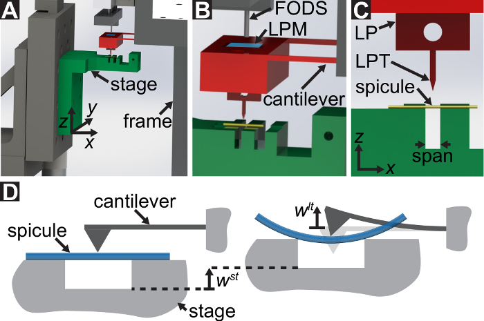
Figure 1: Overview of the custom-built mechanical testing device. (A) A computer aided design rendering of the device. The stage components are highlighted in green. The force sensing subassembly (cantilever, load point (LP)) is highlighted in red. (B) A magnified view of (A). The LP mirror is shown in blue on the top surface of the LP beneath the FODS and is labeled LPM. (C) The coordinate system used to describe the motion of the translation stage. By leveling the stage in step 1.9 of the protocol, the Equation 1 direction is made to coincide with the vector normal to the surface of the LP mirror. (D) A schematic of the three-point bending configuration showing the deformation of the spicule and the measured displacements Equation 49, and Equation 50. Please click here to view a larger version of this figure.

The device's capabilities are demonstrated by performing three-point bending tests on the skeletal elements of the marine sponge Euplectella aspergillum6,7. This sponge's skeleton is an assembly of filaments, called spicules (see Figure 2A). The spicules are ≈50 µm thick and are composed primarily of silica 6. Biosilica-based spicules are found in sponges belonging to the classes Demospongiae, Homoscleromorpha, and Hexactinellida. Sponges, such as E. aspergillum, that belong to the class Hexactinellida are also known as "glass sponges." While the spicules of glass sponges are composed primarily of silica, it has been shown that the silica often contains an organic matrix composed of either collagen 17,18 or chitin 19,20,21. This organic matrix plays an important role in silica biomineralization 18,20. Furthermore, in some spicules the organic matrix also serves as a template for the biomineralization of calcium 22. In addition to being distributed within the silica, the organic matrix can also form distinct layers that partition the spicule's silica into concentric, cylindrical lamellae 6,23. It has been shown that this concentric, lamellar architecture can affect the spicules' deformation behavior 6,7,8,24,25,26. Consequently, the spicules' mechanical properties are determined by a combination of their chemistry (i.e., the chemical structure of the silica-protein composite) and their architecture 27. Both the chemical structure and architecture of glass sponge spicules are still under investigation 24,28,29.

Most of the spicules in E. aspergillum are cemented together to form a stiff skeletal cage. However, at the base of the skeleton there is a tuft of very long (≈10 cm) spicules known as the anchor spicules (see Figure 2A). We describe the protocol for performing three-point bending tests on small sections of the anchor spicules.

In step 1 of the protocol, the procedure for assembling and aligning the components of the custom-built mechanical testing device is described. Steps 2 and 4 of the protocol provide instructions for generating calibration data used to compute forces and displacements in the bending test. The steps taken to prepare a section of a spicule and mount it to the test fixture are described in step 3. The procedure for conducting the bending test on the spicule section is described in step 5. Finally, in the Representative Results section the calibration data obtained in steps 2 and 4 are used along with the bending test data obtained in step 5 to compute Equation 2 and Equation 3.

Figure 2
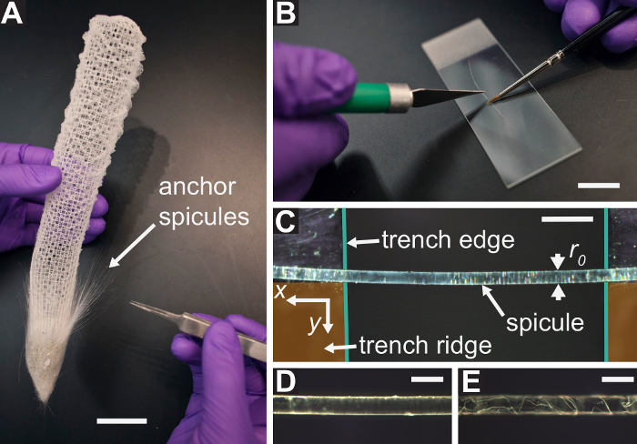
Figure 2: Procedure for sectioning and inspecting E. aspergillum spicules. (A) The skeleton of E. aspergillum. The tuft of free-standing anchor spicules is shown at the base of the skeleton. The scale bar is ~25 mm. (B) A single anchor spicule is held in place on a microscope slide using a #00000 red sable brush and sectioned using a razor blade. The scale bar is ~12 mm. (C) A section of an E. aspergillum spicule placed across the trench on the sample stage. The trench edges and trench ridge are highlighted in teal and orange, respectively. The spicule is pushed against the trench ridge to ensure that its axis is perpendicular to the trench edges. (D) A micrograph of a spicule that passes the inspection procedure described in step 3.4 of the protocol, which describes how to determine if a spicule section is damaged and should be discarded. (E) A micrograph of a spicule containing many cracks and missing large sections of silica layers that would fail the inspection procedure described in step 3.4 of the protocol. Scale bars =  250 µm (C), 100 µm (D), and 100 µm (E). Please click here to view a larger version of this figure.

Protocol

1. Assembly and Alignment Choose a cantilever whose stiffness is appropriate for the intended experiment. Attach the LP to the cantilever using #4-40 socket head cap screws (SHCSs) (see Figure 3A). Take care to not plastically deform the cantilever arms while attaching the LP. Figure 3: Procedure for …

Representative Results

The most basic outputs of any mechanical test are the magnitude of the force applied to the specimen and the displacement at the location where the force is applied. In the case of a three-point bending test, the goal is to obtain the magnitude of the force applied by the LPT, , and the displacement of the specimen's cross-section beneath the LPT in the <img alt="Equation 4" src="/files/ftp_upload/56571/56571eq4.jpg"…

Discussion

Several steps of the protocol are particularly important for ensuring that forces and displacements are measured accurately. While some of these critical steps are universal to all three-point bending tests, others are unique to this mechanical testing device.

In step 1.2 of the protocol the LP mirror is cleaned and inspected for scratches, and in step 1.6 of the protocol the FODS gain is set. It is important for the gain and the LP mirror reflectance to be co…

Divulgazioni

The authors have nothing to disclose.

Acknowledgements

This work was supported by National Science Foundation [Mechanics of Materials and Structures Program, grant number 1562656]; and the American Society of Mechanical Engineers [Haythornthwaite Young Investigator Award].

Materials

TMC 36" x 48" isolation table with 4" CleanTop breadboard TMC 63-563 Isolation Table
Diffeential Screw Adjuster Thorlabs DAS110 For stage leveling plate
1" Travel Micrometer Head with 0.001" Graduations Thorlabs 150-801ME For stage leveling plate
Right-Angle Bracket for PT Series Translation Stages, 1/4"-20 Mounting Holes Thorlabs PT102 For microscope mount
1" Dovetail Translation Stage, 1/4"-20 Taps Thorlabs DT25 For microscope mount
1" Translation Stage with 1/4"-170 Adjustment Screw, 1/4"-20 Taps Thorlabs PT1B For microscope mount
12" Length, Dovetail Optical Rail Edmund Optics 54-401 For microscope mount
2.5" Width, Dovetail Carrier Edmund Optics 54-404 For microscope mount
0.5" Width, Dovetail Carrier Edmund Optics 54-403 For microscope mount
InfiniTube Mounting C-Clamp with ¼-20 Edmund Optics 57-788 Microscope component
Standard (with no In-Line Attachment), InfiniTube Edmund Optics 56-125 Microscope component
Standard In-Line Attachment (Optimized at 2X-10X), InfiniTube Edmund Optics 56-126 Microscope component
Mitutoyo/Achrovid Objective Adapter (M26 to M27) Edmund Optics 53-787 Microscope component
5X Infinity Achrovid Microscope Objective Edmund Optics 55-790 Microscope component
0.316" ID, Fiber Optic Adapter SX-6 Edmund Optics 38-944 Microscope component
¼" x 36", Flexible Fiber Optic Light Guide Edmund Optics 42-347 Microscope component
115V, MI-150 Fiber Optic Illuminator w/IR Filter and Holder Edmund Optics 55-718 Microscope component
Allied Vision Manta G-223 2/3" Color CMOS Camera Edmund Optics 88-452 Microscope component
Power Supply for Manta/ Guppy Pro/ Stingray/ Pike Edmund Optics 68-586 Microscope component
1/4" Travel Single Axis Translation Stage Thorlabs MS1S FODS micrometer
Analog Reflectance Dependent Fiber Optic Displacement Sensor Philtec D20 FODS
30V, 3A DC Power Supply Agilent U8001A Power supply for DAQ and FODS
14-Bit, 48 kS/s Low-Cost Multifunction DAQ National Instruments USB-6009 DAQ for FODS
Three Axis Motorized Translation Stage Thorlabs Thorlabs T25 XYZ-E/M Translation stage
T-Cube DC Servo Motor Controller Thorlabs TDC001 Motor controller for stage
T-Cube Power Supply Thorlabs TPS001 Power supply for motor controller
National Instruments LabVIEW (2013 SP1) National Instruments Used for running software
National Instruments LabVIEW Vision Acquisition Software (2016) National Instruments Used for running software
Nikon Eclipse Ci-POL Main Body MVI MDA96000 Polarized light microscope
Nikon Pi Intermediate Tube with Analyzer Slider MVI MDB45305 Polarized light microscope
Nikon Dia-Polarizer MVI MDN11920 Polarized light microscope
Power Cord – 7'6" MVI 79035 Polarized light microscope
Nikon P-Amh Mechanical Stage MVI MDC45000 Polarized light microscope
Nikon Lwd Achromat Condenser MVI MBL16100 Polarized light microscope
Nikon LV-NBD5BD-CH Manual Quint Nosepiece ESD MVI MBP60125 Polarized light microscope
Nikon C-TF Trinocular Tube F MVI MBB93100 Polarized light microscope
Nikon CFI 10X Eyepiece FN 22mm NC MVI MAK10110 Polarized light microscope
Nikon TU Plan Flour BD 10x Objective MVI MUE42100 Polarized light microscope
Venus Flower Basket Sponge Denis Brand N/A Sponge skeleton
3.5X Headband Flip-Up Magnifier McMaster Carr 1490T5 Used for spicule sectioning
Ø1" Silicon Wafer, Type P / <100> Ted Pella 16011 Used for load point mirror
Low Lint Tapered Tip Cotton Swab McMaster Carr 71035T31 Used for cleaning LP mirror
Rubber grip precision knife McMaster Carr 35575A68 Used for sectioning spicules
Microscope Slides, frosted end, 75 x 25 x 1mm Ted Pella 260409 Used for sectioning spicules
Sable Brushes, #00000, 0.08mm W x 4.0mm L Ted Pella 11806 Used for handling spicules
PELCO Pro High Precision Tweezers, extra fine tips, superior finish Ted Pella 5367-5NM Used for handling spicules
Dual Axis Linear Scale Micrometer Edmund Optics 58-608 Used for calibrating the microscopes
FLEX-A-TOP FT-38 CAS ESD Plastic Containers FT-38-CAS Used for storing spicules
Plastic Vial Bullseye Level McMaster Carr 2147A11 Used for leveling the stage
Analytical Balance Mettler Toledo MS105DU Used to mass calibration weights

Riferimenti

  1. Wegst, U. G., Bai, H., Saiz, E., Tomsia, A. P., Ritchie, R. O. Bioinspired structural materials. Nat. Mater. 14 (1), 23-36 (2015).
  2. Meyers, M. A., McKittrick, J., Chen, P. Y. Structural biological materials: critical mechanics-materials connections. Science. 339 (6121), 773-779 (2013).
  3. Bodde, S. G., Meyers, M. A., McKittrick, J. Correlation of the mechanical and structural properties of cortical rachis keratin of rectrices of the Toco Toucan (Ramphastos toco). J. Mech. Behav. Biomed. Mater. 4 (5), 723-732 (2011).
  4. Gibson, L. J. The hierarchical structure and mechanics of plant materials. J. R. Soc. Interface. , (2012).
  5. Monn, M. A., Kesari, H. A new structure-property connection in the skeletal elements of the marine sponge Tethya aurantia that guards against buckling instability. Sci. Rep. 7, (2017).
  6. Monn, M. A., Weaver, J. C., Zhang, T., Aizenberg, J., Kesari, H. New functional insights into the internal architecture of the laminated anchor spicules of Euplectella aspergillum. Proc. Natl. Acad. Sci. U.S.A. 112 (16), 4976-4981 (2015).
  7. Monn, M. A., Kesari, H. Enhanced bending failure strain in biological glass fibers due to internal lamellar architecture. J. Mech. Behav. Biomed. Mater. , (2017).
  8. Levi, C., Barton, J. L., Guillemet, C., Bras, E., Lehuede, P. A remarkably strong natural glassy rod: the anchoring spicule of the Monorhaphis sponge. J. Mater. Sci. Letters. 8 (3), 337-339 (1989).
  9. Kesari, H., Doll, J. C., Pruitt, B. L., Cai, W., Lew, A. J. Role of surface roughness in hysteresis during adhesive elastic contact. Philos. Mag. Lett. 90 (12), 891-902 (2010).
  10. Croisier, F., et al. Mechanical testing of electrospun PCL fibers. Acta Biomater. 8 (1), 218-224 (2012).
  11. Haque, M. A., Saif, M. T. A review of MEMS-based microscale and nanoscale tensile and bending testing. Exp. Mech. 43 (3), 248-255 (2003).
  12. Gudlavalleti, S. . Mechanical testing of solid materials at the micro-scale. , (2002).
  13. Tohmyoh, H., Ishihara, M., Akanda, M. S., Yamaki, S., Watanabe, T., Iwabuchi, T. Accurate determination of the structural elasticity of human hair by a small-scale bending test. J. Biomech. 44 (16), 2833-2837 (2011).
  14. Waters, J. F. . Contact mechanics of biologically-inspired interface geometries. , (2009).
  15. Dai, Z., Gorb, S. N., Schwarz, U. Roughness-dependent friction force of the tarsal claw system in the beetle Pachnoda marginata (Coleoptera, Scarabaeidae). J. Exp. Biol. 205 (16), 2479-2488 (2002).
  16. Tramacere, F., Kovalev, A., Kleinteich, T., Gorb, S. N., Mazzolai, B. Structure and mechanical properties of Octopus vulgaris suckers. J. R. Soc. Interface. 11 (91), (2014).
  17. Ehrlich, H., et al. Nanostructural organization of naturally occurring composites: Part I. Silica-Collagen-based biocomposites. J. Nanomater. 53, (2008).
  18. Ehrlich, H., et al. Mineralization of the meter-long biosilica structures of glass sponges is templated on hydroxylated collagen. Nat. Chem. 2, 1084-1088 (2010).
  19. Ehrlich, H., et al. First evidence of the presence of chitin in skeletons of marine sponges. Part II. Glass sponges (Hexactinellida: Porifera). J. Exp. Zoo. 308 (4), 473-483 (2007).
  20. Ehrlich, H. Chitin and collagen as universal and alternative templates in biomineralization. Int. Geol Rev. 52, 661-699 (2010).
  21. Ehrlich, H., et al. Supercontinuum generation in naturally occurring glass sponge spicules. Adv. Opt. Mater. 4 (10), 1608-1613 (2016).
  22. Ehrlich, H., et al. Calcite reinforced silica-silica joints in the biocomposite skeleton of deep-sea glass sponges. Adv. Funct. Mater. 21, 3473-3481 (2011).
  23. Werner, P., Blumtritt, H., Zlotnikov, I., Graff, A., Dauphin, Y., Fratzl, P. Electron microscope analyses of the bio-silica basal spicule from the Monorhaphis chuni sponge. J. Struct. Biol. 191 (2), 165-174 (2015).
  24. Kolednik, O., Predan, J., Fischer, F. D., Fratzl, P. Bioinspired Design Criteria for Damage-Resistant Materials with Periodically Varying Microstructure. Adv. Funct. Mater. 21 (19), 3634-3641 (2011).
  25. Weaver, J. C., et al. Unifying design strategies in demosponge and hexactinellid skeletal systems. J. Adhes. 86 (1), 72-95 (2010).
  26. Walter, S. L., Flinn, B. D., Mayer, G. Mechanisms of toughening of a natural rigid composite. Mater. Sci. Eng. C. 27 (3), 570-574 (2007).
  27. Ehrlich, H. Silica biomineralization in Sponges. Encyclopedia of Geobiology. , 796-808 (2011).
  28. Zlotnikov, I., Werner, P., Fratzl, P., Zolotoyabko, E. Eshelby Twist as a possible source of lattice rotation in a perfectly ordered protein/silica structure grown by a simple organism. Small. 11 (42), 5636-5641 (2015).
  29. Zlotnikov, I., et al. A perfectly periodic three-dimensional protein/silica mesoporous structure produced by an organism. Adv. Mater. 26 (11), 1682-1687 (2014).
  30. Gere, J. M., Timoshenko, S. P. Chapter 5: Stresses in Beams. Mechanics of materials. , 205-217 (1997).
  31. Baratta, F. I., Matthews, W. T., Quinn, G. D. . Errors associated with flexure testing of brittle materials. , (1987).
  32. Quinn, G. D., Sparenberg, B. T., Koshy, P., Ives, L. K., Jahanmir, S., Arola, D. D. Flexural strength of ceramic and glass rods. J. Test. Eval. 37 (3), 1-23 (2009).
  33. Tattersall, H. G., Tappin, G. The work of fracture and its measurement in metals, ceramics and other materials. J. Mater. Sci. 1 (3), 296-301 (1966).
check_url/it/56571?article_type=t

Play Video

Citazione di questo articolo
Monn, M. A., Ferreira, J., Yang, J., Kesari, H. A Millimeter Scale Flexural Testing System for Measuring the Mechanical Properties of Marine Sponge Spicules. J. Vis. Exp. (128), e56571, doi:10.3791/56571 (2017).

View Video