Fabrication of Gradient Nanopattern by Thermal Nanoimprinting Technique and Screening of the Response of Human Endothelial Colony-forming Cells
Summary
Here, we present a protocol for the fabrication of gradient nanopattern plates via thermal nanoimprinting and the method of screening responses of human endothelial progenitor cells to the nanostructures. By using the described technology, it is possible to produce a scaffold that can manipulate cell behavior by physical stimuli.
Abstract
Nanotopography can be found in various extracellular matrices (ECMs) around the body and is known to have important regulatory actions upon cellular reactions. However, it is difficult to determine the relation between the size of a nanostructure and the responses of cells owing to the lack of proper screening tools. Here, we show the development of reproducible and cost-effective gradient nanopattern plates for the manipulation of cellular responses. Using anodic aluminum oxide (AAO) as a master mold, gradient nanopattern plates with nanopillars of increasing diameter ranges [120-200 nm (GP 120/200), 200-280 nm (GP 200/280), and 280-360 nm (GP 280/360)] were fabricated by a thermal imprinting technique. These gradient nanopattern plates were designed to mimic the various sizes of nanotopography in the ECM and were used to screen the responses of human endothelial colony-forming cells (hECFCs). In this protocol, we describe the step-by-step procedure of fabricating gradient nanopattern plates for cell engineering, techniques of cultivating hECFCs from human peripheral blood, and culturing hECFCs on nanopattern plates.
Introduction
Recently, the response of cells by the physical stimulation of surface topography has been spotlighted in the field of cell engineering1,2,3,4. Therefore, more attention has been focused on three-dimensional nanostructures at the cell attachment surface5. It has been reported that the integrin, which is the surface recognition device of the cell, transmits the physical stimulus driven by the micro-nano structures of ECM through mechano-transduction6. This mechanical stimulation regulates cell behavior through contact guidance7 and induces cytoskeletal reorganization to change shape, in addition to focal adhesions and stiffness of cells8.
Human endothelial progenitor cells (hEPCs) in the body closely interact with the microenvironment of the surrounding ECM9. This indicates that the physical state of the ECM acts as an important parameter for specific cell-matrix adhesion complex formation as much as shear stress derived from blood flow10. It is reported that surface nanotopography enhances the in vitro formation of extensive capillary tube networks of hEPCs11 and that an ECM/bio soluble factor combined system enables hEPCs to recognize dysfunctional substrates and promotes wound healing12,13. Nonetheless, the relationship between ECM and hEPCs is not clearly understood.
Although many researchers tried to clarify the relationship between cell responses and physical cues from different substrates14,15,16, these studies used only the fixed size of a nanostructure or nanopatterns with irregular arrangements that have a limitation to elucidate the relationship between the size of the nanostructure and cell behavior. The problem here is a lack of suitable tools for screening cellular responses that can replace existing tedious and iterative approaches to find the optimum size of the nanostructure. Therefore, a straightforward technique is required for screening cell reactions on physical stimulations without repetition.
Here, we describe a method used in our previous reports17,18,19 to produce a gradient nanopattern in which the diameter of the arranged nanopillars gradually increases. In addition, we also described how to cultivate and analyze the behavior of hECFCs on gradient nanopattern plates to determine the effect of physical stimuli on the cells. A mild anodization, gradual etching, and anti-sticking layer coating method were used to fabricate gradient AAO mold. By adopting a thermal imprinting lithography technique, identical polystyrene gradient nanopatterns were produced in a cost-effective and facile way. Using gradient nanopatterns, it is feasible to determine which size of nanostructure has a great effect on cell behavior in one set of experiment. We expect that this gradient nanopattern will be helpful in understanding the interaction mechanisms between blood-derived hECFC or other cells and various sizes of nanostructures.
Protocol
This study was approved by the Institutional Review Board at Korea University Anam Hospital (IRB No. ED170495). All procedures were carried out in accordance with the Helsinki Declaration and its later amendments.
1. Preparation of Aluminum (Al) Substrate by Electropolishing
Caution: Electropolishing solution is corrosive and toxic. Wear personal protective equipment including nitrile gloves, goggles and lab coat. Perform this step in a fume hood.
- Prepare electropolishing solution by mixing ethyl alcohol (C2H5OH, 99.9%) and perchloric acid (HClO4, 60%) in a 1 L double jacket beaker (C2H5OH:HClO4 = 4:1).
- Connect the double jacket beaker to a circulator and set the temperature at 7 °C. Put the double jacket beaker on a magnetic stirrer. Leave the solution under stirring for at least 30 min until the temperature drops to 7 °C.
- Immerse the ultrapure Al plate (99.999%, 20 × 50 × 1 mm3) and carbon counter electrode into the electropolishing solution using crocodile clips and copper wire. Adjust the position of the Al plate and the carbon counter electrode to face each other.
Note: It is necessary to install the clips carefully so as not to touch the solution. When in contact with the solution, impurities flowing out from the clips can contaminate the Al plate. - Connect the Al plate to the positive terminal, and carbon counter electrode to the negative terminal, of a direct current (DC) power supply.
- Turn off the magnetic stirrer and apply a voltage of 20 V. Maintain this state for 4 min.
- Turn on the magnetic stirrer, and allow the current to flow for another 6 min.
Note: The static condition removes most of the impurities and roughness from the Al plate, and the dynamic condition improves the final quality of electropolishing. - Turn off the power supply and manually separate the Al plate from the clip. Rigorously wash the Al plate with deionized water to remove all remaining solution.
- Dry the Al plate with nitrogen and store under inert gas. Conduct this drying process at the end of all experiments in step 1 and 2.
Note: When injecting compressed air, make air flow from the polished part to the opposite side. In the opposite case, impurities can escape from the non-polished part and contaminate the Al plate.
2. Fabrication of Gradient AAO Mold with Phosphoric Acid Electrolyte
Caution: Methyl alcohol and its fume are ocular toxic. Continuous exposure to chromium can lead to serious chromium poisoning. Perform this step in a fume hood.
- Primary anodization
- To prepare 1 L of phosphoric acid electrolyte, load 590 mL of deionized water into a glass bottle.
- Add 400 mL of methyl alcohol (CH3OH, 99%) and 10 mL of phosphoric acid (H3PO4, 85%) into the glass bottle. Mix the solution well by shaking manually or with magnetic stirring.
- Pour 500 mL of the electrolyte into a 1 L double jacket beaker. Immerse the polished Al plate and carbon counter electrode into the solution with crocodile clips and copper wire.
- Pour additional electrolyte to locate the boundary of electropolishing 2-3 mm above the surface of the solution.
Note: If anodization is carried out with the boundary of electropolishing touching the solution, the Al plate tends to burn during the anodization. - Install a vertical shaft on a U-shape pedestal. Attach an overhead stirrer, and impeller using metal clamps. Position the propeller of the impeller near the lower end of both electrodes. Set the rotation speed of the overhead stirrer between 200 and 300 rpm.
- Connect the double jacket beaker to a circulator and set the temperature at -10 °C. Leave the system for at least 1 h under stirring until the temperature drops to -10 °C.
Note: Do not use water as the coolant. Because the water freezes at low temperatures, the circulation will not work normally. It is recommended to use a mixture of water and ethyl alcohol at a ratio of 1:1 as the coolant. - Apply a voltage of 195 V under stirring for 16 h.
Note: If the current rises more than 50 mA within 2 or 3 h after applying the voltage, the probability that burning will occur is very high. Immediately stop the process and replace the Al plate with a new one. If this problem occurs repeatedly, check that there is no abnormality in the temperature control of the circulator. If there is no abnormality, change the electrolyte. - Stop the power supply and manually separate the Al plate from the clip. Wash the anodized Al plate with deionized water to remove all remaining solution.
- Alumina etching
- Prepare chromic acid etching solution by dissolving 9.0 g of chromium oxide (CrO3) and 20.3 mL of phosphoric acid (H3PO4, 85%) in 500 mL of deionized water.
- Pour the etching solution into the 1 L double jacket beaker. Set the temperature at 65 °C.
- Immerse the anodized Al plate in the etching solution for at least 10 h under stirring. Seal the top of the beaker with aluminum foil.
- Rinse the etched Al plate several times with deionized water.
- Secondary anodization
- Set the same experimental conditions as step 2.1.1 to 2.1.7.
- Load the etched Al plate to the anode of the system and apply a voltage of 195 V for 6 h. Then, turn off the power supply and manually separate the Al plate from the clip. Immediately wash the anodized Al plate with deionized water.
Note: When the time of washing is delayed, the pore size of AAO increases unintentionally owing to the residual phosphoric acid.
- Gradient pore widening
- Prepare a pore widening solution by dissolving 5.765 g of phosphoric acid in 500 mL of deionized water. Pour the solution into a 1 L double jacket beaker.
- Connect the double jacket beaker to the circulator and set the temperature at 30 °C. Place a linear moving stage vertically next to the beaker. Attach a bracket to the moving part of the linear stage.
- Set the moving part of the linear stage to the home position. Attach the clip to the bracket and load the anodized Al plate.
- Manipulate the position of the Al plate manually so that the Al plate will come right above the surface of the solution.
Note: In this step, the Al plate should not touch the solution. The pore widening process begins as soon as the Al plate reaches the solution. - Gradually immerse the Al plate into the solution at a speed of 4.86 µm/s for 120 min to make a 35 mm AAO mold with a size gradient from 120 nm to 200 nm (GP 120/200). Start a stopwatch at the moment the Al plate touches the surface of the solution.
- To make GP 200/280 and GP 280/360 molds, immerse the entire area of GP 120/200 mold in the pore widening solution for 2 or 4 h, respectively.
- Rinse the gradient Al plate several times with deionized water.
3. Deposition of Anti-Sticking Layer on Gradient AAO Mold with Self-Assembled Monolayer
Note: Perform steps 3.2.1 to 3.3.3 in a glove box. Connect a vacuum pump and dry nitrogen gas injector to the glove box. Place all samples, reagents, and apparatuses in the glove box prior to the dehumidification process. Repeat the evacuation and nitrogen gas injection cycle more than three times to adequately remove moisture from the glove box. Let the dry nitrogen flow through the experiment.
- Hydroxyl modification of AAO mold with Piranha treatment
- Pour 140 mL of sulfuric acid (H2SO4, 95%) in a polytetrafluoroethylene (PTFE) beaker. Add 60 mL of hydrogen peroxide dropwise (H2O2, 30%). Leave it for 30 min until the solution has cooled down.
Caution: Be extremely careful when making Piranha solution. From the moment of adding hydrogen peroxide, the solution vigorously boils and generates high temperatures. Perform the experiment in a fume hood. - Immerse the AAO mold in the solution for 30 s using a nonmetallic tweezer.
- Rinse the AAO mold several times with deionized water. Soak the mold in deionized water for 30 min and put it in methyl alcohol for another 30 min.
Caution: When discarding the used Piranha solution, dilute the solution with a copious amount of tap water. - Completely dry the AAO mold under vacuum for 3 h.
- Pour 140 mL of sulfuric acid (H2SO4, 95%) in a polytetrafluoroethylene (PTFE) beaker. Add 60 mL of hydrogen peroxide dropwise (H2O2, 30%). Leave it for 30 min until the solution has cooled down.
- Preparation of 20× HDFS stock solution
Note: HDFS is an abbreviation of (heptadecafluoro-1,1,2,2, -tetrahydrodecyl) dimethylchloro-silane- Fill one-third of a 1 L n-hexane bottle with molecular sieves. Seal the bottle with paraffin film and store it under dry nitrogen for 24 h.
- Filter the 200 mL of n-hexane using a glass syringe and 0.2 µm PTFE syringe filter.
- Pour the 80 mL of filtered n-hexane into a 100 mL glass bottle. Add 2 mL of HDFS.
- Self-assembled monolayer deposition
- Load 57 mL of filtered n-hexane in a 100 mL beaker. Immerse the AAO mold into the solvent.
- Add 3 mL of HDFS stock solution to the n-hexane to make 2.9 mM HDFS solution. Wait 10 min for the reaction to proceed.
- Transfer the AAO mold to fresh n-hexane. Close and seal all reagent bottles. Close the nitrogen valve, then pull out samples from the glove box.
Note: HDFS is extremely sensitive to moisture. Store all reagents that contain HDFS in a desiccator. - Soak the AAO mold in 60 mL of methoxynonafluorobutane (C10H6F18O2, 99%). Ultrasonically clean the AAO mold in a beaker for 10 s per one time to remove physically adsorbed HDFS molecules. Repeat the cleaning procedure 10 times.
Note: Exposing the AAO mold to ultrasonic for a long time without intervals will damage the oxide layer. - Completely dry the AAO mold under vacuum for 24 h.
Note: A successfully deposited anti-sticking layer is super water repellent and stable for months when stored in a desiccator. The protocol can be paused here.
4. Fabrication of Gradient Nanopattern Plates by Thermal Imprinting
Note: Perform steps 4.2 to 4.7 in a clean room.
- Cut a 1.1 mm thick polystyrene sheet to a size of 2.9 mm wide by 3.7 mm long using a printed circuit board (PCB) cutter.
- Cut the AAO mold 35 mm from the bottom using a nipper. Mark the sample name and date of manufacture on the back.
- Clean an 8.0" wafer with a small dose of ethyl alcohol. Put the polystyrene sheets on the wafer, then mount the AAO mold.
- Put the bottom film in the drawer of a thermal imprinter. Attach the top film to the gasket.
- Put the wafer on the bottom film. Place the gasket on the wafer. Make sure that there is no dust on the wafer.
- Close the drawer of the thermal imprinter. Apply 165 °C of heat and 620.52 kPa of pressure for 100 s.
- Cool the sample to room temperature. Gently twist the polystyrene sheet to release the AAO mold.
5. Sterilization and Hydrophilic Modification of Gradient Nanopattern Plates
- Place the nanopattern plates on a square dish. Pour 100 mL of 70% ethyl alcohol and expose to ultraviolet light for 30 min.
- Dry the nanopattern plates with nitrogen. Transfer the nanopattern plates to an oxygen plasma generator.
- Evacuate the chamber until it reaches 1.33 Pa. Then, inject oxygen at a rate of 30 cm3/min. Apply a radio frequency power of 60 W. Maintain the oxygen plasma for 90 s.
Note: It is recommended to use plasma-treated nanopattern plates within 14 days. - Attach the nanopattern plate to the bottom of a cell culture dish using a drop of toluene.
- Seal the samples in a pouch and sterilize with low-temperature plasma sterilizer.
6. Cultivation of hECFCs
Note: Conduct all centrifuging procedures at 4 °C unless otherwise noted.
- Before isolating the peripheral blood mononuclear cells (PBMCs), incubate a collagen-coated 12-well culture dish at 37 °C for 1 h.
- Wash the 12-well culture dish using 1× sterile phosphate buffered saline (PBS).
- Collect 50 mL of human blood using a heparin inhibitor tube.
- Put 6 mL of hydrophilic polysaccharide solution in a 15 mL tube and add 8 mL of blood to the hydrophilic polysaccharide solution.
Note: Slowly pipette the blood into the hydrophilic polysaccharide solution. - Centrifuge the tube at 1020 x g for 20 min to pellet the cells.
- Harvest the opaque cell layer, and transfer to a new 15 mL tube.
- Add 10% fetal bovine serum (FBS)-contained PBS and centrifuge the tube at 1020 x g for 10 min to pellet the cells.
- Remove the supernatant and add red-blood-cell lysis buffer. Keep on ice for 5 min.
- Add 10% FBS-contained PBS and centrifuge the tube at 1020 x g for 5 min to pellet the cells.
- Remove the supernatant and add 10% FBS-contained PBS. Centrifuge the tube at 1020 x g for 5 min to pellet the cells.
- Remove the supernatant and add 1 mL of endothelial cell expansion medium supplemented with 10% FBS. Seed 8.0 × 10⁶ cells per well for each collagen-coated dish.
- Change the culture medium every day for 1 week. Then, change the culture medium every 2 days.
Note: hECFCs can be found after culture day 10-14. hECFCs show typical cobblestone-like morphology and form a colony which can be observed in phase contrast microscopy. Immunofluorescence staining of vascular endothelial cadherin (CD144) and von Willebrand factor (vWF) can be also performed for the characterization of the hECFCs after further cell expansion. - To cultivate the hECFCs, use endothelial cell expansion medium supplemented with 5% FBS and penicillin/streptavidin at 37 °C in a humidified atmosphere containing 5% CO2. Replace the medium once a day.
- After hECFC induction, grow the cells to passage 7 for further experiments.
7. Cell Seeding and Culture on the Gradient Nanopattern Plates
Note: Step 7 describes the culture of hECFCs on the gradient nanopattern plate, but other cell sources also can be used.
- Coat the gradient nanopattern plates with 1 mL of 0.1% protein coating solution in PBS for 10 min at room temperature.
Note: The 0.1 % protein coating does not cover the nanopillar features. - Make a hECFCs suspension from the culture dish by a standard cell-splitting method using trypsin.
- Dilute the cell suspension to achieve the desired confluence. Seed the hECFCs onto the gradient nanopattern plates and flat control (e.g., 1.0 × 10⁴ cells/cm2).
Note: When hECFCs are seeded at 1.0 × 10⁴ cells/cm2 on gradient nanopattern plates, the cell confluency usually reaches to 70 – 80 % after 2 days. - Culture the cells on flat or gradient nanopattern plates for 2 days in the incubator.
8. Observation and Analysis
- Scanning electron microscope (SEM) imaging
- Fix hECFCs cultured on flat or gradient nanopattern plates with 2.5% glutaraldehyde at 4 °C for overnight .
- Treat 1% osmium tetroxide for 1 h at room temperature. Wash samples with PBS.
- Dehydrate samples with ethyl alcohol from low to high concentration (50%, 70%, 80%, 90%, and 100%) for 10 min per each step.
- Treat hexamethyldisilazane (HMDS) for 15 min at room temperature. After that, wash samples with fresh HMDS and leave samples under the fume hood at least 1 day until the residual HMDS evaporates completely.
- Coat the samples with platinum sputter coater for 5 min and examine the samples with an SEM.
- Transmission electron microscope (TEM) imaging
- Fix hECFCs cultured on flat or gradient nanopattern plates with 2% paraformaldehyde and 2.5% glutaraldehyde mixture in PBS at 4 °C for overnight.
- Perform post-fixation using 1% osmium tetroxide and dehydrate samples using the method in 8.1.3.
- Embed samples in epoxy resin. Make 60 nm thick sections from blocks and place a section on a TEM grid.
- Stain the section with the mixture of 10 mg uranyl acetate in 100 mL methyl alcohol and 0.1 mg lead citrate in 100 mL distilled water. Obtain images with a TEM.
- Fluorescence staining
- Fix hECFCs cultured on flat or gradient nanopattern plates with 4% paraformaldehyde at room temperature for 15 min.
- Permeabilize and block samples with 5% goat serum and 0.1% octylphenol ethoxylate in PBS (PBST) at room temperature for 30 min.
- Incubate samples with anti-human vinculin primary antibody (1:500 in PBST) at room temperature for 2 h. Rinse samples three times with PBST.
- Incubate samples with fluorescence-conjugated phalloidin (1:1,000 in PBST), fluorescence-conjugated secondary antibody (1:1,000 in PBST) at room temperature for 2 h. Rinse samples three times with PBST.
- Incubate samples with 4', 6-diamidino-2-phenylindole (DAPI, 1:1,000 in PBST) at room temperature for 5 min.
- Drop 10 µL of mounting medium on the surface of gradient nanopattern. Place a coverslip on the mounting medium.
- Place the sample upside down on the sample stage and acquire images using confocal fluorescence microscope.
- Image analysis
- Transfer captured images of the hECFCs to an image analysis system.
- Choose the random field of phalloidin staining image. Adjust the threshold and create a binary image in which cells are distinct from the background.
- Draw contours around cells to measure the cell area and perimeter and manually count the filopodia number per cell.
- Choose the random field of vinculin staining image. Adjust the threshold and create a binary image of focal adhesion areas.
Note: Adjust image threshold appropriately to avoid artificial over- or under-filling of focal adhesion areas. - Count the number of focal adhesion of each cell.
Representative Results
Figure 1 shows SEM images of the fabricated gradient AAO molds according to their type and position. Figure 2 shows SEM images of gradient nanopattern plates with regular-rounded nanopillars, and Figure 3 is quantification data of the nanopillar diameter. Table 1 lists the characteristics of the fabricated nanopillars.
Figure 4A shows the scheme of cultivation of blood-derived hECFCs. Figure 4B shows the phase contrast image of thecultivated hECFCs. Figure 4C shows hECFC markers stained with CD144 (green), vWF (red), and nucleus (blue). Figure 5A shows representative SEM images of hECFCs after 2 days of culture on the flat, GP 120/200, GP 200/280, and GP 280/360 plates. Figure 5B and C depict quantitative data on cell area and perimeter as compared to the flat. The quantification data revealed that cells grown on nanopillar surfaces of smaller size showed reduced cell area and perimeter. Figure 5D is the representative SEM images of hECFCs which show the morphology of existing filopodia. Figure 5E depicts the quantitative data on filopodia number as compared to the flat. Significant filopodial outgrowth was observed in cells cultured on GP 120/200, while no significant change was observed in GP200/280 or GP280/360 in comparison with the flat. Figure 5F shows representative TEM images of hECFCs after 2 days of culture on flat and gradient nanopattern plates.
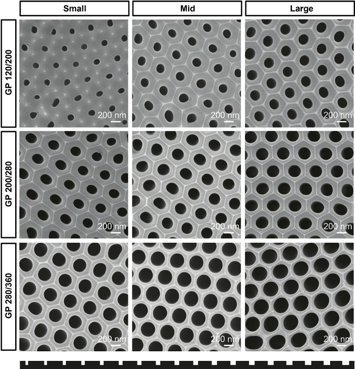
Figure 1. Gradient AAO mold. SEM images of gradient AAO molds for GP 120/200, GP 200/280, and GP 280/360 plates according to the position of molds. Please click here to view a larger version of this figure.
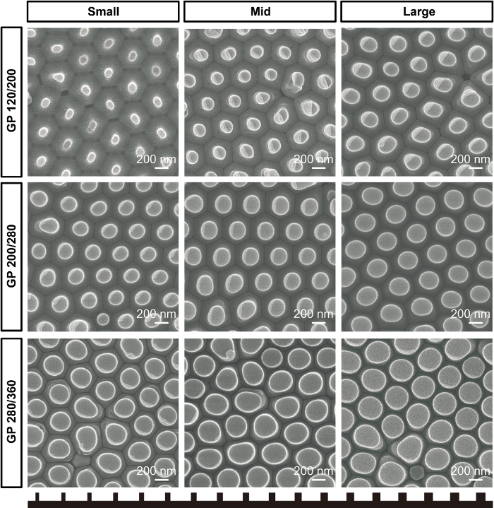
Figure 2. Gradient nanopattern plates. SEM images of pillar-type gradient nanopattern plates for GP 120/200, GP 200/280, and GP 280/360 plates according to position of plates. Please click here to view a larger version of this figure.
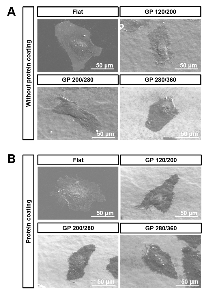
Figure 3. Size gradient of nanopillar diameter. Quantification data showing the gradient of nanopillar diameters for GP 120/200, GP 200/280, and GP 280/360 plates, respectively. Bars represent standard error. This figure was modified from [Acta Biomaterialia]20. Please click here to view a larger version of this figure.
| Young’s modulus (GPa) | Nanopillar Diameter (nm) | Nanopillar Pitch (nm) | Center to Center Distance (nm) | Nanopillar height (nm) | Nanopillar stiffness (N/m) | |
| Flat | 2.43±0.19 | – | – | – | – | – |
| GP 120/200 | 1.74±0.11 | 120–200 | 320–240 | 440 | 276.9±21.9 | 9.35 |
| GP 200/280 | 2.01±0.05 | 200–280 | 240–160 | 440 | 268.1±25.9 | 55.78 |
| GP 280/360 | 2.1±0.13 | 280–360 | 160–80 | 440 | 293.6±23.6 | 134.15 |
Table 1. Characteristics of fabricated nanopillars. Quantified data showing Young's modulus, diameter, pitch, center to center distance, height, and stiffness of fabricated nanopillars. This table was modified from [Acta Biomaterialia]20.
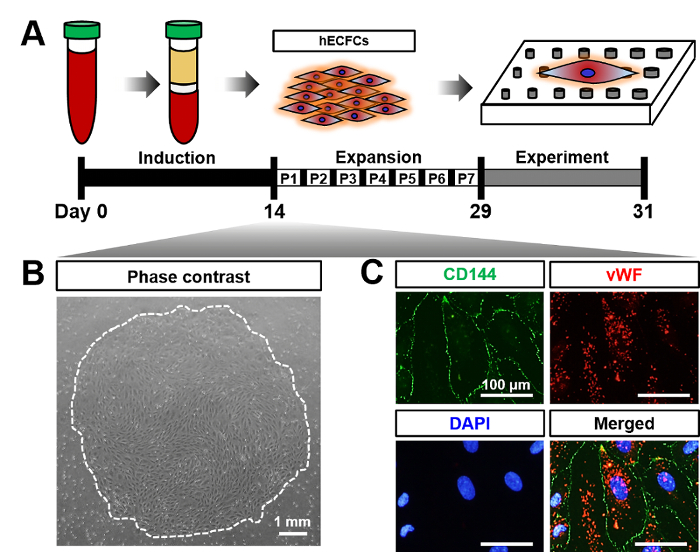
Figure 4. Characterization of hECFCs. (A) Schematic diagram showing schedule of hECFCs derived from adult peripheral blood. (B) Phase contrast image of hECFC colony, derived from adult peripheral blood on day 14. (C) Immunofluorescent images showing CD144 (green), vWF (red), and cell nucleus stained with DAPI (blue). This figure was modified from [Acta Biomaterialia]20. Please click here to view a larger version of this figure.
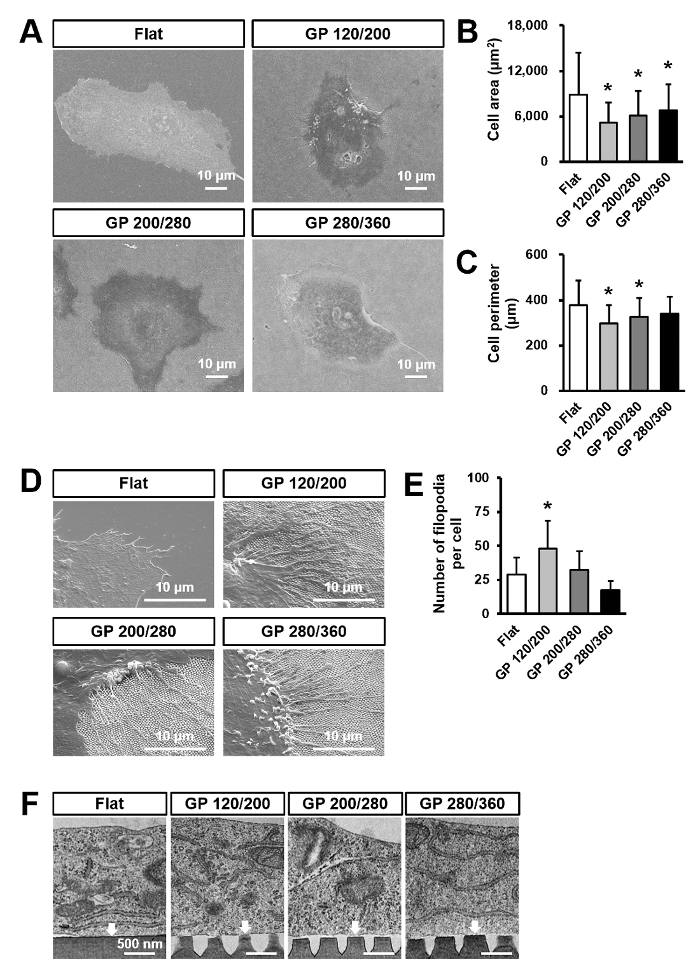
Figure 5. hECFCs cultured on flat and gradient nanopattern plates for 2 days. (A) Representative SEM image of hECFCs cultured on Flat, GP 120/200, GP 200/280, and GP 280/360 plates. (B and C) Quantification data of the area and perimeter of hECFCs (n = 50). *p < .05 as compared to the Flat. (D) Representative SEM images of the leading edge of hECFCs on flat and gradient nanopattern plates. (E) Quantification data of the number of filopodia per one hECFC (n = 20). *p < .05 as compared to the Flat. (F) Representative TEM image of hECFC cultured on Flat and gradient nanopattern plates. White arrows indicate the interaction points between hECFCs and substrate surface. This figure was modified from [Acta Biomaterialia]20. Please click here to view a larger version of this figure.
Supplementary Figure 1. Water contact angle of pristine AAO and HDFS treated AAO. Contact angle measurements showing hydrophobic properties of HDFS self-assembled monolayer (A) before and, (B) after treatment. Please click here to download this figure.
Supplementary Figure 2. SEM images of fabricated gradient nanopattern plates with same AAO mold. Comparative SEM image sets for verifying the durability of AAO mold. (A) Gradient nanopattern plate produced with freshly made mold. (B) Gradient nanopattern plate produced with AAO mold after imprinting 15 times. Please click here to download this figure.
Supplementary Figure 3. Influence of protein coating. SEM images of hECFCs that were cultured on GP 120/200, GP 200/280, or GP 280/360 gradient nanopattern plates (A) without or (B) with the protein coating. This figure was modified from [Acta Biomaterialia]20 Please click here to download this figure.
Discussion
Fabrication of an AAO often suffers from defects such as cracks, irregular shapes of pores, and burning. The main reason for these defects is called an electrolytic breakdown, which is strongly affected by the nature of the metal substrates being anodized and the resistivity of the electrolyte21. Since the resistivity of the electrolyte varies depending on its temperature, eliminating heat continuously from electrodes is the critical point to maintain the locational temperature of the electrolyte as stable in such a high-voltage anodizing condition. In this protocol, we fabricated AAO molds by modifying Masuda's two-step anodization22,23. Replacing almost half the electrolyte with methyl alcohol not only prevents the electrolyte from freezing at low temperatures but also deprives the electrode of heat by evaporation at the bottom of the pore24. The reason for using an overhead stirrer and impeller instead of a magnetic stirrer is also to ensure the temperature control. The typical magnetic stirrer has a high probability of idling owing to the accidental misalignment of the magnetic bar during long-term operation. This problem induces the improper circulation of the electrolyte, raising its temperature, and leading to burning.
To give a size gradient to the AAO mold, we gradually immersed the AAO in a phosphoric acid etching solution. The pores are widened in proportion to the time the AAO stays in the etching solution, as shown in Figure 1. Under this condition, the average pore-widening rate is 0.67 nm/min. Manipulating the immersing speed and time will change the slope of the size gradient and maximum pore diameter of the AAO. The maximum possible pore diameter is 400 nm. When the pore diameter exceeds 400 nm, the spacing wall between pores becomes so thin that it cannot tolerate the pressure during the thermal imprinting process.
An HDFS self-assembled monolayer is known to be able to add a hydrophobic property to the material surface25. The HDFS molecule makes a strong covalent bond with the hydroxyl groups on the AAO surface introduced by the Piranha treatment26. Therefore, as shown in Supplementary Figure 1, a solid self-assembled monolayer can be formed when a large number of hydroxyl groups are present on the substrate surface. For optimum quality with an HDFS self-assembled monolayer, we suggest conducting the reaction in a dehumidified atmosphere. When HDFS is exposed to moisture, a side reaction with water forms dimers, trimers, and even oligomers of silane molecules, and decreases the overall quality of the self-assembled monolayer.
Upon using the AAO mold with a size gradient in thermal nanoimprinting, cell culture plates with a gradient of nanopillars were obtained Figure 2 and Figure 3. The thermal nanoimprinting method has an advantage in that it can produce a large quantity of identical nanopattern plates by using one AAO master mold. Supplementary Figure 2 shows that there is no difference in the quality of the nanopattern produced, even after fifteen imprinting processes, compared to the nanopattern produced by the new AAO mold. The reason for choosing polystyrene as a material for transferring a nanopattern is that the polystyrene has an appropriate glass transition temperature (100 °C) for thermal imprinting, and it is widely used in commercial cell culture dishes owing to its transparent and nontoxic properties.
Fabricating nanostructures with high aspect ratio using thermal nanoimprinting method is difficult. Because, when process conditions, such as pressure and time increase, the mold becomes deeply embedded into the polymer substrate, making it hard to separate the mold from the substrate. Therefore, it is very challenging to produce nanopatterns having an aspect ratio of 1:3 or more using our nanoimprinting technique. However, according to TEM images we observed Figure 5C, we have found an interesting fact that the membrane of cells on nanopatterns was not in contact with the bottom of the nanopattern. In other words, all physical stimuli that can manipulate a response of cells were originated from the top parts of the nanopattern. Therefore, in this study, we did not have to consider the aspect ratio in studying responses of the cell to the nanopattern. As shown in Supplementary Figure 3, 0.1% protein coating solution had no influence on the attachment of hECFCs on the nanopillar surfaces. Furthermore, these nanoscaled stimuli from the gradient nanopattern plates decreased the cell area and perimeter of hECFCs and increased filopodial outgrowth Figure 5.
In summary, we established gradient nanopattern plates by manipulating a response of hECFCs in vitro. To know exactly what size of nanostructures the cells are greatly affected, a future work is required to design a cell-specific-sized nanopillar by adjusting the slope of the size gradient and minimum-maximum diameter of the nanopillars. We expect this gradient nanopattern to be a fascinating tool to screen the interaction between cells and nanostructures as well as provide advanced cell niches in which nanostructures can be freely tuned in size.
Divulgazioni
The authors have nothing to disclose.
Acknowledgements
This work was supported by the Basic Science Research Program through the National Research Foundation of Korea (NRF) funded by the Ministry of Education, Science and Technology (MEST) [NRF-2015R1D1A1A01060397] and Bio & Medical Technology Development Program of the NRF funded by the Ministry of Science, ICT & Future Planning [NRF-2017M3A9C6029563].
Materials
| Perchloric acid 60% | Daejung Chemicals & Metals | 6512-4100 | |
| Ethyl alcohol, absolute 99.9% | Daejung Chemicals & Metals | 4118-4100 | |
| Phosphoric acid 85% | Daejung Chemicals & Metals | 6532-4400 | |
| Methyl alcohol 99.5% | Daejung Chemicals & Metals | 5558-4400 | |
| Chromium(VI) oxide | Daejung Chemicals & Metals | 2558-4400 | |
| Sulfuric acid 95% | Daejung Chemicals & Metals | 7781-4100 | |
| Hydrogen peroxide 30% | Daejung Chemicals & Metals | 4104-4400 | |
| n-hexane 95% | Daejung Chemicals & Metals | 4081-4400 | |
| Toluene 99.5% | Daejung Chemicals & Metals | 8541-4400 | |
| (heptadecafluoro-1,1,2,2,-tetrahydrodecyl)dimethylchlorosilane | Gelest | SIH5840.4 | Moisture sensitive |
| Methoxynonafluorobutane 99% | Sigma aldrich | 464309 | |
| Collagen solution | Stemcell | #4902 | |
| Gelatin | Sigma aldrich | G1890 | Protein coating solution |
| Ficoll-Paque | GE Heathcare | 17-1440-03 | Hydrophilic polysaccharide solution |
| EGM-2MV | Lonza | CC-3202 | Endothelial cell expansion medium |
| Penicillin-Streptomycin | Gibco | 15140-122 | |
| Phosphate buffered saline | Gibco | 10010031 | |
| Fetal bovine serum | Gibco | 12483-020 | |
| Paraformaldehyde | Sigma aldrich | P6148 | |
| Glutaraldehyde | Sigma aldrich | G5882-100ML | |
| Osmium tetroxide | Sigma aldrich | 201030-1G | |
| Hexamethyldisilazane | Sigma aldrich | 440191 | |
| Triton X-100 | Sigma aldrich | X100-100ML | Octylphenol ethoxylate |
| Goat serum | Gibco | 26050-088 | |
| anti-human vinculin primary antibody | Sigma aldrich | V9131 | |
| F-actin probe | Molecular Probes | A12379 | Fluorescence-conjugated phalloidin |
| Alexa Fluor 488-conjugated anti-mouse IgG antibody | Molecular Probes | A11001 | Fluorescence-conjugated secondary antibody |
| 4',6-diamidino-2-phenylindole | Sigma aldrich | D9542 | |
| Mounting medium | DAKO | S3023 | |
| Anti-human vWF primary antibody | DAKO | A0082 | |
| Anti-human CD144 primary antibody | BD Biosciences | #555661 | |
| Eponate 12™ Embedding Kit, with BDMA | Ted Pella | 18012 | Epoxy resin |
| Uranyl Acetate, 25g | Ted Pella | 19481 | |
| Lead Citrate, Trihydrate, 10g | Ted Pella | 19312 | |
| Ultra pure aluminum plate | Goodfellow | 26050-088 | |
| Polystyrene sheet | Goodfellow | ST313120 | |
| 8.0" silicon wafer | Siltron | 29-01024-03 | Single side polished, 725 µm thick |
| Vacuum desiccator, 4.4 L | Kartell | KA.230 | |
| Vacuum pump | Vacuumer | V3.VOP100 | |
| Power supply | Unicorntech | UDP-3003 | |
| Magnetic stirrer | Daihan scientific | SL.SMS03022 | |
| Overhead stirrer | Daihan scientific | HT120DX | |
| Circulator | Daihan scientific | WCR-P12 | |
| Linear moving stage | Zaber | A-LSQ300A-E01-KT07 | |
| Angle bracket, 90 degrees | Zaber | AB90M | Accessory of the linear moving stage |
| PMP forcep, 145 mm | Vitlab | 67995 | Nonmetallic tweezer |
| PTFE beaker, 250 mL | Cowie | CW007.25 | |
| Ultrasonic cleaner | Branson | B2510MTH | |
| PCB cutter | Hozan Tool Industrial | K-110 | |
| Nanoimprint device | Nanonex | NX-2000 | |
| Oxygen plasma generator | Femto Science | CUTE | |
| Low temperature sterilizer | Lowtem | Crystal 50 | |
| CO2 Incubator | Panasonic | MCO-18AC | |
| Confoal laser scanning microscope | Carl Zeiss | LSM700 | |
| Scanning electron microscope | JEOL | JSM6701 | |
| Transmission electron microscope | Hitachi | H-7500 |
Riferimenti
- Dalby, M. J., Gadegaard, N., Oreffo, R. O. Harnessing nanotopography and integrin-matrix interactions to influence stem cell fate. Nature materials. 13 (6), 558-569 (2014).
- Qian, W., Gong, L., Cui, X., Zhang, Z., Bajpai, A., Liu, C., Castillo, A., Teo, J. C., Chen, W. Nanotopographic Regulation of Human Mesenchymal Stem Cell Osteogenesis. ACS Applied Materials & Interfaces. 9 (48), 41794-41806 (2017).
- Naganuma, T. The relationship between cell adhesion force activation on nano/micro-topographical surfaces and temporal dependence of cell morphology. Nanoscale. 9 (35), 13171-13186 (2017).
- Han, J., Lin, K. H., Chew, L. Y. Study on the regulation of focal adesions and cortical actin by matrix nanotopography in 3D environment. Journal of Physics: Condensed Matter. 29 (45), 455101 (2017).
- Liu, X., Wang, S. Three-dimensional nano-biointerface as a new platform for guiding cell fate. Chemical Society Reviews. 43 (8), 2385-2401 (2014).
- Turner, L. A., Dalby, M. J. Nanotopography-potential relevance in the stem cell niche. Biomaterials science. 2 (11), 1574-1594 (2014).
- Driscoll, M. K., Sun, X., Guven, C., Fourkas, J. T., Losert, W. Cellular contact guidance through dynamic sensing of nanotopography. ACS nano. 8 (4), 3546-3555 (2014).
- Yim, E. K., Darling, E. M., Kulangara, K., Guilak, F., Leong, K. W. Nanotopography-induced changes in focal adhesions, cytoskeletal organization, and mechanical properties of human mesenchymal stem cells. Biomaterials. 31 (6), 1299-1306 (2010).
- Davis, G. E., Senger, D. R. Endothelial extracellular matrix. Circulation research. 97 (11), 1093-1107 (2005).
- Nakayama, K. H., Surya, V. N., Gole, M., Walker, T. W., Yang, W., Lai, E. S., Ostrowski, M. A., Fuller, G. G., Dunn, A. R., Huang, N. F. Nanoscale patterning of extracellular matrix alters endothelial function under shear stress. Nano letters. 16 (1), 410-419 (2015).
- Bettinger, C. J., Zhang, Z., Gerecht, S., Borenstein, J. T., Langer, R. Enhancement of in vitro capillary tube formation by substrate nanotopography. Advanced materials. 20 (1), 99-103 (2008).
- Katz, B. Z., Zamir, E., Bershadsky, A., Kam, Z., Yamada, K. M., Geiger, B. Physical state of the extracellular matrix regulates the structure and molecular composition of cell-matrix adhesions. Molecular biology of the cell. 11 (3), 1047-1060 (2000).
- Deanfield, J. E., Halcox, J. P., Rabelink, T. J. Endothelial function and dysfunction. Circulation. 115 (10), 1285-1295 (2007).
- Tajima, S., Chu, J., Li, S., Komvopoulos, K. Differential regulation of endothelial cell adhesion, spreading, and cytoskeleton on low-density polyethylene by nanotopography and surface chemistry modification induced by argon plasma treatment. Journal of Biomedical Materials Research Part A. 84 (3), 828-836 (2008).
- Mohiuddin, M., Pan, H. A., Hung, Y. C., Huang, G. S. Control of growth and inflammatory response of macrophages and foam cells with nanotopography. Nanoscale research letters. 7 (1), 394 (2012).
- Kyle, D. J., Oikonomou, A., Hill, E., Bayat, A. Development and functional evaluation of biomimetic silicone surfaces with hierarchical micro/nano-topographical features demonstrates favourable in vitro foreign body response of breast-derived fibroblasts. Biomaterials. 52, 88-102 (2015).
- Seo, H. R., Joo, H. J., Kim, D. H., Cui, L. H., Choi, S. C., Kim, J. H., Cho, S. W., Lee, K. B., Lim, D. S. Nanopillar Surface Topology Promotes Cardiomyocyte Differentiation through Cofilin-Mediated Cytoskeleton Rearrangement. ACS Applied Materials & Interfaces. 9 (20), 16803-16812 (2017).
- Hwang, J. H., Lee, D. H., Byun, M. R., Kim, A. R., Kim, K. M., Park, J. I., Oh, H. T., Hwang, E. S., Lee, K. B., Hong, J. H. Nanotopological plate stimulates osteogenic differentiation through TAZ activation. Scientific Reports. 7 (1), 3632 (2017).
- Bae, D., Moon, S. H., Park, B. G., Park, S. J., Jung, T., Kim, J. S., Lee, K. B., Chung, H. M. Nanotopographical control for maintaining undifferentiated human embryonic stem cell colonies in feeder free conditions. Biomaterials. 35 (3), 916-928 (2014).
- Cui, L. H., Joo, H. J., Kim, D. H., Seo, H. R., Kim, J. S., Choi, S. C., Huang, L. H., Na, J. E., Lim, I. R., Kim, J. H. Manipulation of the response of human endothelial colony-forming cells by focal adhesion assembly using gradient nanopattern plates. Acta biomaterialia. 65, 272-282 (2017).
- Lee, W., Park, S. J. Porous anodic aluminum oxide: anodization and templated synthesis of functional nanostructures. Chemical reviews. 114 (15), 7487-7556 (2014).
- Masuda, H., Fukuda, K. Ordered metal nanohole arrays made by a two-step replication of honeycomb structures of anodic alumina. science. 268 (5216), 1466 (1995).
- Masuda, H., Satoh, M. Fabrication of gold nanodot array using anodic porous alumina as an evaporation mask. Japanese Journal of Applied Physics. 35 (1B), L126 (1996).
- Zaraska, L., Sulka, G. D., Jaskuła, M. The effect of n-alcohols on porous anodic alumina formed by self-organized two-step anodizing of aluminum in phosphoric acid. Surface and Coatings Technology. 204 (11), 1729-1737 (2010).
- Yang, K. Y., Kim, J. W., Byeon, K. J., Lee, H. Selective deposition of the silver nano-particles using patterned the hydrophobic self-assembled monolayer patterns and zero-residual nano-imprint lithography. Microelectronic engineering. 84 (5), 1552-1555 (2007).
- Park, B. G., Lee, W., Kim, J. S., Lee, K. B. Superhydrophobic fabrication of anodic aluminum oxide with durable and pitch-controlled nanostructure. Colloids and Surfaces A: Physicochemical and Engineering Aspects. 370 (1), 15-19 (2010).
