EHD jet printing has been widely used in various areas, such as printed electronics, biotechnology, and advanced material applications, because it is capable of high-resolution and low-cost direct patterning1. The printed line width or printed dot size could be reduced to 1 µm, which is significantly smaller than that of conventional piezo-based inkjet printing1.
In EHD printing, a small portion of ink (or meniscus) is pushed out of the nozzle tip and maintained by controlling the flow rate1,2,3,4,5 or the positive air pressure1,6,7. The extruded meniscus is charged and can easily be pulled down from the nozzle tip to the substrate by an electric field, as shown in Figure 1. The conical meniscus is formed during the jetting, producing an ink stream much thinner than the nozzle size.
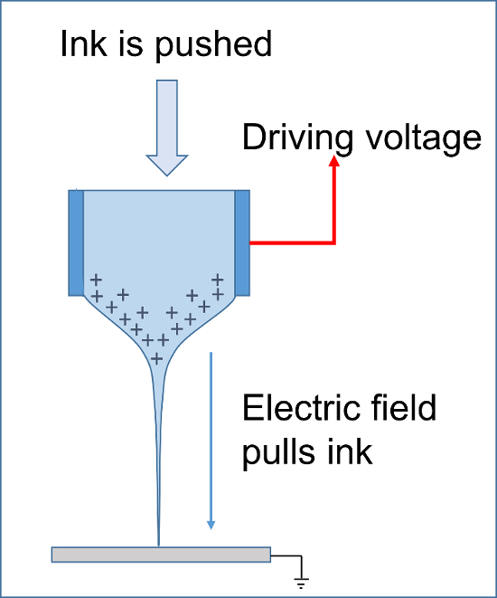
Figure 1: EHD printing. The figure shows the principle of EHD jet printing. Ink is pushed via pressure and pulled via an electric field to form an extruded meniscus from the nozzle. Then, the charged ink can be easily jetted to the substrate via a DC or pulse voltage. Please click here to view a larger version of this figure.
Even though a single EHD printer can be used for the two different modes, near-field electrospinning (NFES) and drop-on-demand (DOD) EHD jet printing, the realization methods significantly differ in terms of ink, fluidic system, and driving voltage1,2,3. For example, NFES4,5 uses a relatively high-viscous ink [more than 1,000 centipoises (cP)] to form continuous micro-line patterns with high-speed printing up to 1 m/s. On the other hand, DOD EHD jet printing6,7,8 uses low-viscous ink with a viscosity of around 10 cP to print dot-based complex patterns with a low printing speed less than 10 mm/s.
Since the requirement for each mode is significantly different, it may be challenging for inexperienced researchers to achieve the desired results. The empirical "know-how" might be important in practice. To help researchers get used to the printing methods, we present EHD printing protocols for fine conductive patterning using Ag nanoparticle ink. However, we added comments to the protocols so that they are not limited to a conductive patterning using Ag nanoparticle ink. Finally, printing and preparation guidelines are presented in the discussion section.
For health and safety purposes, prior to using any ink and cleaning solution, refer to the material safety datasheet (MSDS).
1. Drop-on-demand Electrohydrodynamic Jet Printing Using Silver Nanoparticle Ink
- Fill the filtered silver nanoparticle (AgNP) ink in the ink reservoir of the EHD printing system.
Note: Commercially available AgNP ink can be used for the inkjet purpose. The ink should have a viscosity of around 10 cP and a surface tension of 20 ~ 40 mN/m to obtain drop-on-demand jetting. - Make a nozzle for the DOD EHD printing by using a thermal puller.
- Place a glass capillary [inner diameter (ID) of 1 mm] in the thermal puller.
- Set the parameters of the thermal puller; for example, the heating temperature in the range of 580 – 590 °C and a pulling speed of around 18 mm/s.
Note: The parameters for the thermal puller should differ according to the target nozzle ID and ambient conditions. - Operate the thermal puller with the set parameters to apply heat at the center of the capillary and pull at both of its ends to make a nozzle with an ID of 5 µm.
Note: Determine the size of the nozzle ID based on the target dot size on the substrate. For reference, the nozzle ID of 5 µm could print 5 µm-sized dots. - Adjust the glass nozzle length by cutting the glass nozzle via a glass cutter.
- Assemble the nozzle to the nozzle holder and the connector, which are connected to the ink reservoir via polytetrafluoroethylene (PTFE) tubing.
- Apply the air pressure to supply ink to the nozzle tip.
- Turn on the air-pressure controller and apply air pressure of 15 ~ 20 kPa to the ink reservoir to supply ink to the nozzle tip. Monitor the ink flow through the transparent glass nozzle and tubing to ensure that no air is trapped inside the tube and the nozzle when supplying the ink. Keep applying air pressure to the ink reservoir until ink appears at the nozzle tip.
Note: Do not reduce the pressure before the ink appears at the nozzle tip because that could cause air bubble entrapment at the nozzle tip. - Reduce the pressure to around 12 kPa to maintain the extruded meniscus without any ink dripping from the nozzle tip.
Note: The proper air pressure depends on the nozzle size and ink viscosity. Do not increase the air pressure to more than 30 kPa to avoid excessive air compression, which is undesirable for maintaining the meniscus in a stable condition.
- Turn on the air-pressure controller and apply air pressure of 15 ~ 20 kPa to the ink reservoir to supply ink to the nozzle tip. Monitor the ink flow through the transparent glass nozzle and tubing to ensure that no air is trapped inside the tube and the nozzle when supplying the ink. Keep applying air pressure to the ink reservoir until ink appears at the nozzle tip.
- Fix the assembled nozzle head in the printing system.
- Place a glass substrate on the vacuum chuck of the substrate holder and turn on the vacuum pump to hold the substrate.
- Move the Z-axis stage to adjust the stand-off distance (H)—the gap between the nozzle tip and the substrate position—to approximately 100 µm. Use the side-view image acquired by the monitoring camera to estimate the stand-off distance by using the distance from the nozzle tip to its reflection, as shown in Figure 2.
Note: A smaller stand-off distance leads to a higher electrical field, which could facilitate printing with a lower DC and pulse voltages for jetting. However, a lower stand-off distance could lead to larger drops. Therefore, the magnitude of voltages should be reduced accordingly to obtain the desired dot size. In general, the use of a lower voltage is recommended to obtain smaller printed dots with less spraying. However, a careful operation is required if the stand-off distance becomes less than 50 µm, due to the higher chance of nozzle breakage by collision with the substrate. Considering the trade-off relationship between jetting ability and reliability, we recommend the use of a stand-off distance of 100 µm.
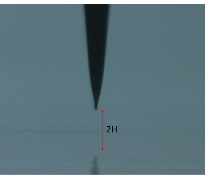
Figure 2: Stand-off distance adjustment by using side view camera image. The nozzle image from a side-view camera can be used to estimate the stand-off distance. The stand-off distance (H) from the nozzle tip to the substrate can be easily estimated as half the distance from the nozzle tip to its shadow. Please click here to view a larger version of this figure.
- Apply DC and pulse voltages
Note: The DC and pulse voltages can be controlled via the printing software.- Increase the DC voltage gradually until the ink drips out of the nozzle tip.
Note: Do not apply the target voltage at once. The incremental voltage should be less than 100 V at a time. Overall, do not apply a DC voltage of more than 600 V. - Reduce the DC voltage slightly from the onset DC voltage until no further ink dripping from the nozzle is observed.
Note: After the adjustment of the pneumatic pressure and DC voltage, the meniscus should be in an appropriate shape for jetting as shown in Supplementary Figure S1. - Set a negative pulse voltage with the parameters of trise = 0 ~ 100 µs, tdwell = 300 µs, and tfall = 0 µs7 (Figure 3) in the software menu.
- Apply the negative pulse voltage at the substrate holder. Then, adjust the magnitude of the pulse voltage, Vpulse, to produce one droplet per single pulse voltage.
Note: The magnitude of the negative pulse voltage, Vpulse, should be lower than 600 V. - Adjust the DC background and pulse voltages to obtain the target droplet size on the substrate while observing the jetted dots on the substrate in the side view camera image.
Note: To produce small dots with less spraying on the substrate, the magnitude of the pulse voltage, Vpulse, should be as low as possible.
- Increase the DC voltage gradually until the ink drips out of the nozzle tip.
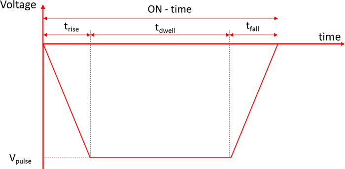
Figure 3: Pulse voltage for DOD EHD jetting. The use of trapezoid waveform voltage is recommended to produce DOD EHD jetting7. Please click here to view a larger version of this figure.
- Print patterns
Note: Two different kinds of patterns can be used for DOD EHD printing: bitmap image and (CAD)-based vector information. Bitmap image has been widely used in DOD-based inkjet printing. However, in the case of printed electronics applications, CAD-based vector information has advantages over DOD-based inkjet printing, because it is efficient in line-based printing using a single EHD head. At the same time, the vector information can be converted into a bitmap image for bitmap image printing.- Bitmap image printing
- Load a bitmap image in the printing tab of the printing software and convert it into a binary image.
- Set the parameters for the binary image printing. For instance, set the drop interval (i.e., the distance between 2 consecutive pixels) at 10 µm.
Note: The bitmap image does not have any physical dimensions. The physical dimensions of the printed image will be related to the drop interval. For example, the printed image becomes larger if a larger drop interval is used. In conventional inkjet printing, dot per inch (DPI) has been commonly used for this purpose. However, it should be noted that a smaller DPI means a larger drop interval. In order to determine the drop interval, the printed dot size should be considered. In general, the drop interval for EHD DOD printing is significantly smaller than that of conventional inkjet printing. - Start printing using the selected bitmap on the target location in the substrate.
- Vector printing based on CAD information
- Load the CAD information for printing.
Note: The file format DXF, which is text-based CAD information, can be used for the printing information. - Set the parameters for vector printing; for example, set the drop interval at 3 µm and the jetting frequency at 10 Hz.
Note: To print the connected line patterns, the drop interval should be chosen so that adjacently deposited drops slightly overlap. However, too much overlapping may result in a larger line width. An overlapping of about 30% is recommended for any practical line printing. In the case of vector printing, the motion speed (v) the following equation.
v = d × f
Here,
d = the drop interval, and
f = the jetting frequency. - Print the loaded patterns on the substrate using pre-determined printing parameters, such as the drop interval, the printing speed, the voltage, etc.
Note: After printing, a sintering process might be required to obtain the desired conductivity of the printed patterns, which is beyond the scope of this paper.
- Load the CAD information for printing.
- Bitmap image printing
2. Fine Conductive Line Patterning Using Near-field Electrospinning
- Make near-field electrospinning (NFES) ink for conductive line printing.
- Mix ethanol and deionized (DI) water with a volume ratio of 3 (ethanol) to 1 (DI water) to prepare solvent 1. For example, mix 9 ml of ethanol and 3 ml of DI water to make 12 ml of solvent 1.
- Mix 0.3 g of poly (ethylene oxide) (PEO, Mwt = 400,000) and 9.7 g of the prepared solvent 1 to make a polymer solution with 3 wt% of PEO by stirring, using a magnetic stirrer for more than 6 h at room temperature (25 °C).
- Mix Ag nano paste ink, which has a viscosity of about 11,000 cP, and the prepared polymer solution, with a weight ratio of 5 (Ag nano paste ink) to 1 (polymer solution) by using a vortex mixer for 10 min to obtain the ink for NFES. For example, 10 g of Ag nano paste ink and 2 g of polymer solution can be mixed to obtain the NFES ink.
Note: In this protocol, the ratio of the mixing materials is generally more important than the specific amount of the materials. Commercially available Ag nano paste ink for screen printing purposes, which has Ag solid contents of about 85.5 wt%, can be used for this purpose. Note that the selection of the solvent and the polymer could differ based on the composition of the ink that is used.
- Fill the prepared NFES ink in the syringe.
- Connect the syringe with a nozzle via the connecting tube.
Note: A commercially available syringe needle with an ID of 100 µm can be used for the nozzle. - Supply the ink to the nozzle by pushing the syringe manually.
- Install the syringe in the syringe motor, which is attached to the printing system.
- Place a substrate on the vacuum chuck and turn on the vacuum pump to hold the substrate during the printing.
- Control the Z-position (stage) to adjust the stand-off distance.
Note: The recommended stand-off distance should be around 2 mm, which is a significantly smaller stand-off distance compared to the one used with conventional electrospinning. - Adjust the flow rate
- Operate the syringe pump to fill the NFES ink in the nozzle assembly and generate an ink flow with an initial flow rate of 50 µL/min, which is higher than the target flow rate.
- Set a target flow rate of 1 µL/min when the ink flows out of the nozzle tip.
Note: A smaller flow rate can result in a smaller pattern width. However, it could cause line breakage. The trade-off between the line width and the continuation of the line should be considered when the target flow rate is determined.
- Apply voltage
- Connect the DC voltage source to the nozzle connector and connect the ground voltage to the substrate holder.
- Increase the DC voltage gradually to 1.5 kV.
Note: Since the stand-off distance is in the range of a few millimeters, the DC voltage could be increased up to 2 kV, which is higher than that of DOD EHD jet printing. However, a DC voltage higher than 2 kV should be avoided since it might damage the functional material, especially Ag paste ink, added to the polymer solution. In general, a lower DC voltage is recommended when a thinner printed line is required. However, the printed lines could be easily disconnected when a low voltage is used, because the pulling force for continuous ink printing is related to the DC voltage. Considering the trade-offs, we recommend the use of a DC voltage ranging from 1 kV to 2 kV.
- Start the idle printing with a printing speed of 300 mm/s for more than 10 min to obtain a steady-state flow. Adjust the printing parameters such as the DC voltage and flow rate during the idle printing to obtain the desired printing results.
Note: Idle printing of more than 10 min is required to obtain a steady-state flow because the viscous ink can be compressed in the lengthy tubing during the ink delivery to the nozzle tip. Without idle printing, the printed line width may change with time. The idle printing speed should, thus, be the same as the actual printing speed so that the jetting parameters can be adjusted during the printing. In this way, the DC voltage is adjusted during the idle printing to obtain the target line width. Note that the flow rate and DC voltage should be balanced, so that the amount of ink pushed by the syringe pump can be equal to the amount of ink pulled down by the electrical field. - Choose the printing pattern, such as a continuous line and grid patterns.
Note: Since the produced fiber can easily be deflected and can be randomly deposited because of the charge repulsion force generated by the printed lines, the printing speed should be greater than 300 mm/s to align the pattern with the printing directions, and the spacing between the printed lines is recommended to be more than 100 µm in order to print the gird or line patterns. - Print the selected pattern on the substrate using pre-determined printing parameters.
Note: A sintering process might be required to obtain the target functionalities of the printed patterns, which is beyond the scope of this paper.
Dot-based drop-on-demand printing:
DOD printing is based on one droplet jetting per one jetting trigger. To produce DOD jetting, low-viscous ink with a viscosity of approximately 10 cP should be used. The ink requirement for EHD DOD printing is similar to that of the conventional DOD inkjet, as is the EHD printing method to that of the conventional DOD inkjet. In the case of conventional inkjet printing, the raster printing technique has been widely used, because it is suitable for bitmap image printing using multi-nozzle heads. However, in the case of an EHD jet printing, there is a limit on the implementation of the multi-nozzle head due to the electrical cross-talk among nozzles. Thus, vector printing using a single nozzle is commonly used for CAD-based line printing. Nonetheless, either the raster or the vector printing mode should be selectable from the printing software to print various types of patterning. Note that the algorithm and implementation can differ according to the printing modes. In the vector mode, simultaneous movements in the x, y directions are used to print the lines, whereas, in raster printing, a single axis is used to print dots in the main direction and then move to the next swath in the sub-direction. Representative printing results using raster and vector printing are shown in Figure 4.
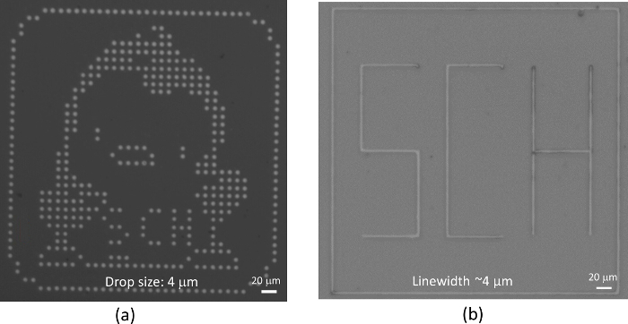
Figure 4: Typical printing results using DOD EHD jetting. (a) This panel shows bitmap printing (raster printing). (b) This panel shows vector printing based on CAD information. Dot-based EHD jet printing can be used to print both bitmap images (raster printing) and CAD-based lines (vector printing). Here, DC voltages of 250 V and a pulse voltage of -250 V were used to print both patterns. In panel a, the drop interval was set to 10 µm in order to separate the dots. In panel b, the pattern was printed using a frequency of 10 Hz and a drop interval of 3 µm so that the dots are connected to form lines.
Near-field electrospinning:
NFES uses highly viscous ink of more than 1,000 cP to print patterns continuously. So, it cannot print bitmap images nor CAD information with printing and non-printing locations. As a result, instead of complicated patterns, NFES is suitable for printing straight lines by using a high printing speed. Grid patterns are commonly used as shown in Figure 5.
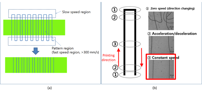
Figure 5: Typical printing result of NFES. (a) This panel shows a typical grid pattern for electrospinning printing. (b) This panel shows the effect of the printing speed on the printing result. NFES requires a high printing speed for two purposes: to reduce the pattern width and to align the printing patterns with respect to the printing direction. Since the jetting behavior is unpredictable in the slow printing region, the fast printing region should be used by excluding the non-straight-line parts.
To print continuous patterns using NFES, the printing speed should be faster than 300 mm/s to align the printed patterns with the printing direction. A fast printing speed also helps to achieve a thin pattern width11. The reduction ratio of the pattern width with respect to the nozzle ID could be more than 20x, depending on printing conditions. For example, a nozzle ID of 100 µm could produce a pattern width smaller than 5 µm. So, NFES is a very effective method to achieve very fine patterns using highly viscous ink. However, the pattern straightness and width are easily subject to the printing speed variation. Note that there are unavoidable acceleration and deceleration regions where the printing speed can become very low (or zero) to change the printing direction. In those regions, the printed patterns could become non-uniform and non-aligned with respect to the moving direction. Therefore, we recommend the use of the printed patterns near the high-speed region only. The printed patterns near acceleration and deceleration regions (the low printing speed regions) should be discarded, as shown in Figure 5a. In some cases, a low jetting speed can be used to generate a wave pattern. By using a low printing speed of less than 100 mm/s, the patterns can become wavy, as shown in Figure 6. The wavy pattern might be useful in stretchable electronics applications. However, the line width can increase up to more than 10 µm because of the low printing speed.
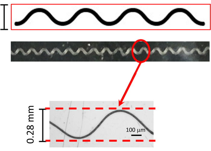
Figure 6: Example of wavy patterns by using the low printing speed. A low printing speed (about 100 mm/s) can produce wavy lines. Please click here to view a larger version of this figure.
In some printing applications, extremely fine patterns with a width smaller than 1 µm are required. To achieve such a fine pattern, a printing speed as fast as 1 m/s can be considered. However, an excessively high printing speed can result in disconnected (or broken) lines. So, various printing conditions such as the flow rate, line width, printing speed, and stretchability of the polymer should be optimized in order to print fine patterns without any line breakage. For example, Figure 7 shows the flow rate effects on the printing results when the printing speed and DC voltage are 300 mm/s and 1,200 V, respectively.
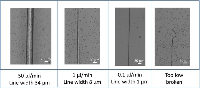
Figure 7: Pattern width according to the flow rate. The flow rate is related to the pattern width. With a lower flow rate, a finer pattern can be obtained. For example, if the flow rate is high with 50 µL/min, the linewidth would be large with 34 µm. When the flow rate reduces to 1 µL/min and 0.1 µL/min, finer patterns with a width of 8 µm and 1 µm, respectively, can be obtained. Note that if the flow rate is too small, the line pattern can be broken and disconnected. Please click here to view a larger version of this figure.
Figure S1: Standby meniscus shape according to printing conditions. The proper meniscus shape should be maintained throughout the printing process by means of proper air pressure and a DC background voltage in order to obtain stable DOD jetting. Please click here to download this file.
Figure S2: Schematic of electrospinning printing. The components for electrospinning printing are shown. Note that a high DC voltage was applied to the nozzle holder to supply electrical charges to the ink and produce the electrical field that pulls the ink to the substrate. In case of NFES, the stand-off distance from the nozzle tip to the substrate should be 1 ~ 3 mm for straight-line printing along the printing direction. Please click here to download this file.
In this protocol, we focus on printing fine patterns using AgNP ink with two modes: DOD EHD printing and NFES. However, the EHD jet printing application is not limited to the conductive ink using AgNP. Here, we will discuss the general guidelines for the selection of ink, the system configuration, and other printing parameters needed to use EHD jet printing for various fine-pattern applications.
The first and most important step for EHD printing is ink selection and preparation. The ink used in the conventional inkjet printing can be used in DOD EHD printing. The viscosity of ink for DOD inkjet printing is in the range of 1 ~ 50 cP (typically 10 cP)14. However, it should be noted that the pneumatic control method for DOD EHD printing is different from that of a conventional DOD inkjet. Conventional inkjets use negative pressure to maintain the meniscus location inside of the nozzle surface to prevent any ink dripping and nozzle wetting. On the other hand, EHD DOD printing uses positive pressure, which can push the ink to form an extruded meniscus. Note that if the ink viscosity becomes more than 100 cP, the meniscus is difficult to control, because air can then easily be compressed rather than push ink to the nozzle tip. The viscosity range for jetting can depend on the nozzle ID. If a smaller nozzle ID is used, the viscosity should be reduced accordingly in order to supply the ink to the nozzle tip without too much air compression.
The surface tension of the ink is also important for proper jetting. The surface tension of the ink should be in the range of 20 – 40 mN/m. If the surface tension is less than 20 mN/m, spraying effects will dominate. If the surface tension is more than 40 mN/m, it will be difficult to form a conical meniscus, which is needed for proper EHD jetting.
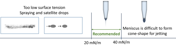
Figure 8: Surface tension effects of EHD jetting. The recommended surface tension for ink is in the range of 20 – 40 mN/m. If the surface tension becomes low, the spraying effects on the substrate will dominate. On the other hand, if the surface tension is too high, proper EHD jetting is unlikely, because the conical meniscus is difficult to achieve. Please click here to view a larger version of this figure.
If the surface tension of an ink is more than 40 mN/m, a small amount of surfactant can be added to the ink to reduce the surface tension. However, the use of excessive surfactant could cause spraying of ink on the substrate. Note that charged ink with the some polarity can produce a repulsive force during the jet flight, resulting in spraying on the substrate. To reduce the spraying effects, the reduction of either the driving voltages or the stand-off distance can be considered.
Another important parameter for reliable jetting is the boiling point. Since the nozzle ID is very small in the case of an EHD jet, the extruded meniscus, due to positive pressure, can easily be dried and clog the nozzle. To reduce any ink drying on the nozzle tip, the main solvent should be selected based on the fact that its boiling point is higher than 150 °C. To prevent any clogging due to particle aggregation, consider filtering the ink with filters with pores one size smaller than the nozzle ID. Also, the particles in the ink should be at least 10x smaller than the nozzle ID. In general, the inks that are suitable for a conventional piezo inkjet can also be used for DOD EHD printing.
NFES ink has higher viscosity compared to that of DOD EHD inkjet ink. The viscosity should be in the range of several thousand cP. For a continuous printing, a polymer solution is mixed with functional ink. The application of NFES has recently been extended from fiber production15,16 to various applications by mixing functional materials with the polymer solution17. For the polymer solutions, PEO and PVP (polyvinylpyrrolidone), etc.4,5,17,18,19, which have a high molecular weight, are commonly used. The main concern with NFES is to preserve the continuous printing capability using the polymer while the ink keeps the material's functionality, such as conductivity. Therefore, the mixing ratio of the polymer solution with respect to the functional materials should be selected carefully. Also, unlike the case of DOD, a solvent with a lower boiling point (less than 100 °C) has typically been used to make the polymer solution.
Even though a conventional inkjet ink can be used in DOD EHD printing, the pressure control methods for EHD printing are different from that of a conventional inkjet. EHD printing uses positive pressure to maintain the extruded meniscus from the nozzle, while a conventional inkjet uses negative pressure. For positive pressure control, two types of pressure control methods—hydrostatic pressure and pressured air—could be used, depending on the ink viscosity and nozzle ID as shown in Figure 9. For a smaller nozzle, air pressure rather than hydrostatic pressure should be used to push the ink to the nozzle tip. However, a proper control of air pressure can be difficult when using high-viscosity ink or a nozzle with an ID less than 2 µm, since the air can be easily compressed. On the other hand, if the nozzle size is more than 50 µm, a slight variation of air pressure can affect the meniscus location. If the ink viscosity is low and the nozzle is more than 50 µm, hydrostatic pressure using fluidic height should be used to maintain a consistent meniscus location.
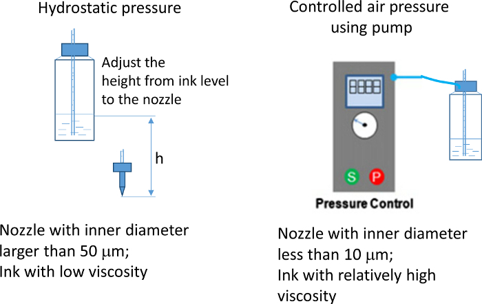
Figure 9: Pressure control for DOD jetting. Positive pressure is necessary to maintain the extruded meniscus at a standby status. The pressure for the meniscus can be controlled by either the hydrostatic pressure (using the height difference between the ink reservoir and the nozzle tip) or the compressed air from an air compressor. The selection of the control methods should differ according to the nozzle size and ink viscosity. Please click here to view a larger version of this figure.
In the case of NEFS, a syringe pump can be used to feed the ink to the nozzle since the highly viscous ink cannot be pushed by air pressure. Note that the ink can be pressurized and compressed when it is supplied at a constant flow rate via a syringe pump. Also, considerable time might be required for the compressed ink to reach a steady-state flow at the nozzle tip. To minimize the ink-compression effects on printing, the connecting tube inserted between the syringe and the nozzle tip should be as short as possible. Also, the connecting tube should be hard to minimize the expansion effects caused by the pressured viscous ink. To minimize the ink compression effects, the syringe should be attached to the printing equipment (stages) to reduce the length of the tube connecting the syringe to the nozzle. For this purpose, we used a syringe pump of which the screw motor can be separated from the controller, as shown in Figure 10.
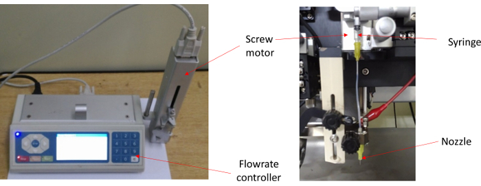
Figure 10: A Fluidic system for electrospinning. The fluidic system for electrospinning consists of two parts: the syringe pump system and the syringe-nozzle assembly. The syringe pump system includes a flow rate controller and a screw motor. Please click here to view a larger version of this figure.
One of the important parameters to determine the dot size or pattern width is the nozzle ID. Unlike the conventional inkjet head, an EHD head does not require any actuators or complex fluid channels. It requires only a nozzle such as a syringe needle or a glass capillary nozzle, which is connected to a high voltage source. Here, the proper size of the nozzle ID should be chosen based on the ink viscosity as well as the pattern width. For example, in the case of a DOD printing using a viscosity lower than 100 cP, the nozzle ID should be less than 50 µm. To obtain stable and consistent printing, the extruded meniscus at standby status should remain in the same location. However, when a nozzle with an ID larger than 50 µm is used, slight variations of air pressure, driving voltage, and stand-off distance can easily affect the meniscus location of low-viscous ink. Note that a meniscus location is related to the jetting amount: a lower location usually produces more droplets. Consequently, when using a nozzle with a large ID, it is very difficult to obtain dot uniformity throughout the DOD printing process. Therefore, the nozzle ID should be less than 10 µm to ensure printed dot-size uniformity. The use of a nozzle with a smaller ID has the advantage of printing smaller dots. For example, a nozzle ID with 3 µm could print dots as small as 3 µm, and the dot size can be further reduced by using a nozzle with smaller ID. To make a nozzle with a small ID, a glass capillary is commonly used, because the nozzle with the target ID can be easily made via a commercially available thermal puller. On another hand, NFES needs a nozzle ID that is greater than 50 µm, to print high viscosity (greater than 1,000 cP) ink. Normally, a nozzle with an ID of 100 µm is commonly used for fine-pattern printing with a pattern width of less than 5 µm. Here, a commercially available syringe needle can be used for this purpose.
In both DOD EHD jet and NFES jetting, ink viscosity should be considered to select the nozzle ID. Also, the amount of pressure (or flow rate) in the fluidic system should be determined based on the nozzle ID and ink viscosity. Figure 11 shows the relationships among three important factors: ink viscosity, nozzle size, and air pressure (or flow rate). As shown in Figure 11, both high pressure and a nozzle with a large ID should be used when using high-viscous ink, whereas low air pressure and a nozzle with a smaller ID should be used for jetting low-viscous ink.
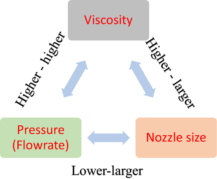
Figure 11: The nozzle selection guideline with respect to viscosity and pressure. This figure explains the relationship between the nozzle ID, viscosity, and pneumatic pressure. For example, if a highly viscous ink is used, a larger nozzle and/or higher air pressure are needed, or vice versa. Similarly, for meniscus control, higher air pressure is needed when using a nozzle with a smaller ID, or vice versa. Nonetheless, high air pressure cannot push the ink properly to the nozzle tip if the nozzle ID is very small or the viscosity is too high because the air could easily be compressed. Please click here to view a larger version of this figure.
During printing, the outer part of the nozzle may be wetted by the ink flows from the nozzle tip. In the presence of significant wetting, proper jetting control can be difficult. The possible cause of wetting might either be from improper ink properties, such as surface tension, or from an improper setting of parameters such as DC voltage and pressure/flow rate. If the wetting on the nozzle persists, nozzle surface treatment might be required so that the nozzle surface can have hydrophobic characteristics with respect to ink.
For DOD printing, two different types of voltage sources are required7,11: a DC background voltage to maintain the standby meniscus shape, and a pulse voltage to generate DOD jetting. However, NFES uses only DC voltage to print continuous micro-line patterns using very highly viscous ink (more than 1,000 cP). The high DC voltage ranging from 1 kV to 2 kV was applied to the metal connector inserted between the nozzle and the tube. To print a straight line, we used the short stand-off distance of 1 ~ 3 mm, and that is why the method is called "near-field" electrospinning (NFES), which has different features compared to the conventional far-field electrospinning12,13.
In this protocol, a glass substrate was used for the experiments, but different types of substrate can be used according to the applications. However, it should be noted that substrates that have a high insulation property [for example, polyethylene terephthalate (PET) film] need pretreatment, such as a chemical coating, to remove the electrical static charges which might be accumulated on the surface.
To use an EHD jet for various applications, the printing and preparation guidelines are summarized in Table 1.
| DOD EHD jet printing | Near field electrospinning (continuous printing) | |
| Ink requirement | Viscosity range: 1~100 cP. | Viscosity: 100 cP ~ 10,000 cP. |
| Surface tension: 20-40 mN/m. | Boiling point: less than 100 °C. | |
| Boiling point of solvent: more than 150 °C. | ||
| Fluidic system | Fluid height (hydrostatic force): nozzle with inner diameter of more than 50µm. | Syringe pump with constant flow rate. |
| Air pressure: nozzle with inner diameter less than 10 µm. | ||
| Nozzle inner diameter requirement | No more than 10 µm is recommended for stable jetting. | More than 100 µm can be used for thin patterning with width less than 5µm. |
| In general: inner diameter with 5 µm can print about dots with size of 5µm. | ||
| Voltage requirement | DC background voltage: less than 600 V | DC voltage: less than 2 kV. |
| Pulse voltage for jetting: a few hundreds of volts. | ||
| Printing speed | Low, less than 10 mm/s. | Faster than 300 mm/s. |
| Software requirement | Raster printing (bitmap image). | Simple grid patterns. |
| Vector printing (CAD based information). | Patterning with on-off requirement is impossible because of the continuous nature of jetting. |
Table 1: The summary of preparation and printing guidelines for DOD and continuous EHD jet. The table summarizes the requirements and recommendations for fine patterning using the EHD jet.
