Observing and Quantifying Fibroblast-mediated Fibrin Gel Compaction
Summary
Time-lapse microscopy and image processing techniques were used to observe and analyze fibroblast-mediated gel compaction and fibrin fiber realignment in an environmentally controlled bioreactor over a 48 hr period.
Abstract
Cells embedded in collagen and fibrin gels attach and exert traction forces on the fibers of the gel. These forces can lead to local and global reorganization and realignment of the gel microstructure. This process proceeds in a complex manner that is dependent in part on the interplay between the location of the cells, the geometry of the gel, and the mechanical constraints on the gel. To better understand how these variables produce global fiber alignment patterns, we use time-lapse differential interference contrast (DIC) microscopy coupled with an environmentally controlled bioreactor to observe the compaction process between geometrically spaced explants (clusters of fibroblasts). The images are then analyzed with a custom image processing algorithm to obtain maps of the strain. The information obtained from this technique can be used to probe the mechanobiology of various cell-matrix interactions, which has important implications for understanding processes in wound healing, disease development, and tissue engineering applications.
Introduction
An important tool for studying cell-matrix interactions is the cell populated collagen gel1,2. The gel provides a 3D environment that is closer to the in vivo character of the tissue and better suited for understanding cell behavior than is offered by traditional 2D cultures3. Early studies in which fibroblasts were homogenously distributed within a collagen gel found that the cells rapidly consolidate the collagen fibers and compact the gel4,5. The contractile fibroblasts in free floating gels then transition into a quiescent state soon after the gel has fully reached compaction1,6,7. The fibroblasts in gels that are constrained at the boundaries remain in an active, synthetic state8 and they generate fiber alignment in a manner dependent on gel geometry and external constraints5,9. Differences in cell activity appear to be a result of the internal tension (or lack thereof) that develops as the cells exert traction forces via integrins on the collagen fibers in the gel.
A variant of this technique involves placing fibroblast explants (i.e. clumps of cells) a distance apart within a collagen gel and observing cell-matrix interactions and the gradual development of fiber alignment between the explants (sometimes called ligament-like straps)10-12. The primary advantage of the explant system is that it allows one to arrange the cells into simple geometric patterns, which makes it easier to visualize and probe the mechanisms underlying cell-driven fiber realignment. These alignment patterns — which are dependent primarily on the interplay between cell traction forces, cell spatial distribution, gel geometry, and the mechanical constraints on the gel — are important to understand because they play a central role in global tissue organization, mechanical function, and local mechanical environment13.
In the field of tissue engineering, one strategy for producing mechanically functional, engineered-tissues involves controlling the fiber alignment pattern that develops from cell compaction so that the engineered tissue possesses fiber alignment that mimics that of the native tissue14,15. Such alignment is believed necessary for engineered tissues to replicate the complex mechanical behavior of native tissues. A modification of this strategy is to replace the collagen gel with a fibrin gel16. The fibrin gel develops a similar alignment pattern as a collagen gel during compaction. Over time the fibrin is degraded and replaced with cell-synthesized ECM that follows the initial fibrin fiber alignment pattern. The resulting engineered construct has significantly improved mechanical properties compared to collagen gel derived constructs17.
The alignment process and subsequent remodeling events in fibrin gels proceed in a complicated and poorly understood manner. To better characterize these interactions and their effect on cell behavior and ECM remodeling, we have developed a procedure that is based on the explant method. In this method, fibroblast explants are positioned on a fibrin gel in different geometric patterns. The gels are maintained in an environmentally-controlled, microscope-mounted bioreactor18, and the process of compaction and fiber realignment is monitored with time-lapse differential interference contrast (DIC) microscopy. Displacement fields are quantified with custom algorithms. The data obtained from these experiments have wide ranging implications for a number of processes, including optimizing tissue engineering strategies, improving wound healing, and treating pathological tissue remodeling.
Protocol
1. Stencil Preparation
Prepare a stencil on Parafilm to layout the location of each explant, following the desired geometry (Figures 1A and 1B). Space each explant approximately 1-2 mm apart. This distance corresponds to an ideal spacing for generating fiber alignment between explants. Attach the stencil underneath the area of the coverglass where the sample will be prepared with tape.
2. Sterilization
Thoroughly clean all components of the bioreactor using 70% ethanol and sterilize for 2-3 hr under UV light prior to experimentation. If an alternative vessel is being used in lieu of a bioreactor then proper sterilization techniques should be used. See step 4.12 for comments on using a glass bottom Petri dish.
3. Fibrin Gel Preparation
After the components of the bioreactor have been sterilized, cast a thin layer of fibrin gel on the surface of the coverglass. Details for preparing fibrinogen and thrombin stock solutions for making 6.6 mg/ml fibrin gels are described in Sander et al.13 A similar protocol by Ye et al.19 for making 3.3 mg/ml fibrin gels can also be viewed on the JoVE website.
- Prepare a solution of fluorescent microbeads in DMEM at a concentration of 10 million beads/ml. The beads will be used to help track gel displacements. To achieve this concentration, combine 0.017 ml of microbead stock solution and 0.149 ml of DMEM into a microcentrifuge tube.
- Sonicate this suspension for 10 min to disperse the beads and homogenize the solution.
- Fibrin Solution — In a 15 ml c-tube, mix 0.22 ml of fibrinogen stock solution with 0.44 ml of 20 mM HEPES buffer. Add the 0.1667 ml of DMEM with microbeads created in step 3.1.
- Thrombin Solution — In a separate 15 ml c-tube, mix together 0.0328 ml of thrombin stock solution, 0.131 ml of 20 mM HEPES buffer, and 0.00246 ml of 2 M CaCl2.
- Carefully mix the thrombin solution (step 3.4) with the fibrinogen solution (step 3.3) by pipetting up and down 5-10x until the solution is evenly distributed. Avoid introducing bubbles as much as possible. To reduce the amount of bubbles produced, be careful not to fully discharge the pipette while mixing.
- The addition of thrombin will cause the solution to gel quickly (~30 sec). Pipette the mixed solution onto the coverglass as soon as possible. Allow the gel to polymerize at RT.
- Seal up the bioreactor, insert the heating blocks, and connect the thermocouples to the temperature controller. Incubate the gel at 37 °C for 15-30 min.
4. Cell Explant Preparation
- Remove medium from the T-75 flask containing the human dermal fibroblast cells.
- Carefully rinse the surface with approximately 5 ml of phosphate buffered saline (PBS) to remove serum proteins. Add 1 ml of trypsin-EDTA and incubate for 3 min, or until cells have lifted.
- After the cells have been lifted, spin the suspension down in a centrifuge at 200 x g for 5 min. Remove the supernatant and resuspend the pellet in a volume of DMEM that will allow a final concentration of 20 million cells/ml.
- While the cells are spinning down in the centrifuge disconnect the bioreactor from the heating blocks and the thermocouples. Transfer the bioreactor to a biosafety cabinet and carefully remove the lid following asceptic techniques.
- Create explants by pipetting 0.3 µl of the cell suspension onto the polymerized fibrin gel, following the pattern on the stencil. Each explant should contain approximately 6,000 cells. Make sure that low volume micropipette tips are used (0.1-10 µl).
- Allow cells to settle and attach to the fibrin matrix for 1 hr at 37 °C.
- With the bioreactor still open, add approximately 5 ml of DMEM supplemented with 10% fetal bovine serum (FBS), 1% penicillin-streptomycin, 0.1% amphotericin B, and 10 mg/ml aprotinin directly into the bioreactor chamber. DMEM is bicarbonate buffered and requires 5% CO2 to maintain a neutral pH. Since the bioreactor is not supplied with CO2, condition the medium in an incubator with 5% CO2 for 2-3 hr before use. Aprotinin is a serine protease inhibitor that is widely used to reduce the rate of fibrin degradation20.
- Reseal the bioreactor. Use a syringe to deliver an additional 5 ml of CO2 conditioned medium via the barbed fitting on the inlet port. Dispense the medium slowly and make sure the entire volume of the bioreactor chamber is filled. Carefully remove bubbles that form in the bioreactor.
- Supply fresh, 5% CO2 conditioned medium to the bioreactor throughout the experiment in order to maintain pH, supply nutrients, and remove waste products. Setup a syringe pump with a 10 ml or 30 ml syringe filled with 5% CO2 conditioned medium. Connect the syringe directly to the inlet port on the bioreactor lid with Luer-lock fitted sterile tubing. Remove the male fitting and attach the tubing to the barbed fitting on the bioreactor (see Figure 1C).
- Set the perfusion rate to 0.01 ml/min. Connect modified pieces of tubing to both outlet ports and place the ends into a 100 ml beaker to collect waste.
- Use a lab jack to set the heights of the inlet and outlet feeds so that a pressure differential does not develop in the bioreactor (consult Figure 1D for reference).
- If a bioreactor is not available, prepare samples in 35 mm glass bottom Petri dishes with glass tops. Use one with a coverslip size that is optimized for the specific set of objectives to be used. Samples that are prepared in Petri dishes should be maintained in an incubator at 37 °C and 5% CO2.
Note: Polystyrene depolarizes light and will interfere with DIC imaging, so glass tops should be used if DIC imaging will be conducted. Phase contrast is a suitable alternative imaging modality. Transferring dishes between the incubator and microscope will make image registration difficult. If images are not properly registered then the strain calculated in Section 6 will not be accurate.
5. Time-lapse Imaging
- Once the sample has been prepared, reseal the bioreactor, reconnect the heating blocks and the thermocouples, and set the bioreactor temperature to 37 °C.
- Set the bioreactor onto the microscope mounted motorized stage. Position the 20X DIC objective under the view-port. A lower magnification objective is acceptable, particularly if a precision motorized stage is not available. Ensure that the polarizer, analyzer, and prism are all in place. Alternatively, samples can also be imaged using phase contrast.
- Open the imaging software.
- Focus the objective on the area between the three explants.
- Save the coordinates (x, y, and z) of this location in the imaging software.
- In order to image the entire area between and around the explants select the option to acquire a large image and specify the size of the area. This will allow the acquisition of multiple images around the specified area and create a tiled image that represents a larger region of the sample.
- Set the exposure time and light intensity to the lowest values possible to avoid cell death caused by phototoxicity, while still providing sufficient resolution to discriminate between cells, microbeads, and fibrin fibers.
6. Strain Tracking
For details and instructions on the strain tracking software (Figure 2) used see Raghupathy et al.21 The algorithm is a custom MATLAB code that can be downloaded from http://www.license.umn.edu/default.aspx. Note that DIC images often have enough texture for strain tracking. The microbeads are included to serve as a check on the calculated strain fields. If strain tracking will be done it is critical that the images obtained are taken at the exact same location so that the images are registered. Unregistered images will produce spurious strains.
Representative Results
Tissue remodeling is a complex process that is driven in part by reciprocal physical interactions between cells and the surrounding matrix. The cells reorganize the surrounding fibers and generate tension in the fiber network. The alignment of fibers and mechanical environment in turn controls cell behavior, so that both cells and matrix globally reorganize to produce remodeled tissue. In this experiment, the cells of the explants, initially round in morphology, began to extend into the gel and adhere to the fibrin fibers (Figure 3). The cells exerted traction forces that propagated through the gel and induced fiber alignment parallel to the axis between explants. Within hours the "straps” became visible (Figure 3A). Strain measurements also indicated that the largest strains are transverse to the axis between explants (Figures 3D and 3E). The strains are highest in this region because the fibers in this region are free to translate towards the axis.
This protocol provides a simple model for the study of cell-induced matrix remodeling and the effects of fiber alignment on cell behavior. The use of cell explants provides a means for easily controlling the spatial distribution of clusters of cells (i.e. explants). The explants also concentrate cell-generated forces so that fiber alignment is quickly generated in a small area that can be easily imaged. High-resolution tiled images of the explants and the surrounding area are then used to quantify matrix reorganization (Figures 3B and 3C) in response to variations in experimental conditions.
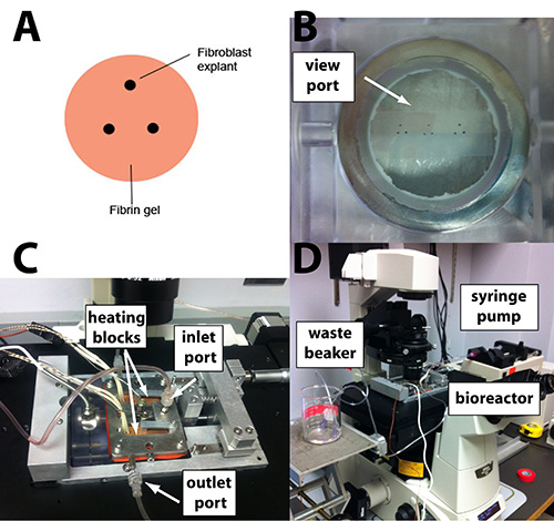
Figure 1. (A) Schematic of a triangular explant configuration on a fibrin gel. (B) A Parafilm stencil taped to the underside of the bioreactor view port can be used to guide explant placement. (C) The assembled bioreactor is (D) placed on the precision motorized stage for time-lapse imaging. A syringe pump supplies conditioned medium at a constant rate. A beaker collects outflow medium. It is positioned at an appropriate height to minimize pressure differences in the bioreactor.
Click here to view larger image.
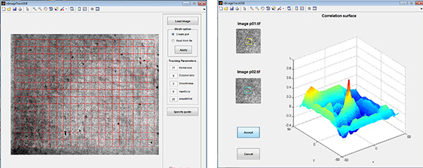
Figure 2. Strain Tracking GUI. Left: A grid is created over the area of the DIC image that will be analyzed. Right: The algorithm, which is based on spatial correlation, finds the pixel displacements between images that result in the highest correlation (i.e. the peak).
Click here to view larger image.
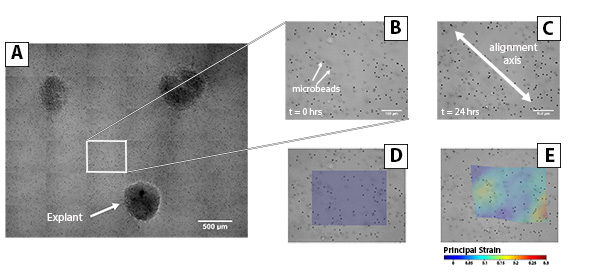
Figure 3. Time-Lapse Microscopy and Strain Tracking of Fibrin Reorganization Between Explants. (A) Fiber realignment was observed between explants by capturing tiled images using a 20X DIC objective. Individual frames were extracted from the tiled image at (B) t = 0 hr and (C) t = 24 hr to analyze fiber reorganization in the area between cell explants. (D) Contour plots show the distribution of maximum principal strain in the area corresponding to the "strap".
Click here to view larger image.
Discussion
This protocol was developed for the purpose of observing and quantifying the mechanics involved in cell-mediated ECM remodeling. Such processes underlie a number of biological phenomena and have important implications for engineering tissues2,22, reducing scar1,23, and understanding pathological tissue remodeling12,24. The use of time-lapse DIC microscopy allows one to resolve and quantify the displacement and alignment of fibrin fibers that occurs as a result of cell traction forces. The reorganization observed here is the first stage of the remodeling process, and it follows the organizational patterns observed in collagen11. Reorganization is followed by a combination of fibrin degradation and ECM synthesis. Whereas the reorganizational stage of remodeling takes place over a few hours to a few days, the synthesis stage of the remodeling process takes weeks to unfold13. The system described here is capable of operating for weeks, and so it can be adapted to monitor these later-stage events.
Possible modifications to this technique may involve varying the location, number, and size of the explants to create different geometries and observe differences in alignment patterns. Explants can also be embedded within the gel instead of on the surface by placing the explants between fibrin layers. Other modifications may involve the use of other fiber forming gels instead of fibrin, such as collagen, or adding other extracellular matrix proteins, such as fibronectin or hyaluronic acid.
Regardless of which set of experimental variables is chosen, experiment success critically depends on cell attachment. Therefore, it is important that one uses the microscope to check that the explants have attached to the gel surface before adding culture medium, as fluid shear can remove the explants from the fibrin gel. Another challenge one might encounter is keeping the cells of the explant together when pipetting them onto the gel. If this becomes an issue one can modify step 4.4 so that the cell pellet is resuspended in equal amounts of DMEM and freshly mixed 0.5 mg/ml reconstituted type I collagen. Adding a dilute amount of collagen can help keep the cells of the explant together. This procedure may be compared to the nested collagen matrices method developed by Grinnell et al., where cell migration and changes in collagen microstructure can also be studied by placing cell-populated collagen gels into acellular collagen gels25,26. Obtaining focused images throughout the experiment is also very important. Maintaining focus can be difficult because the explants move downward as the gel compacts and decreases in thickness. As a result, refocusing will be required as long as the gel compacts. Finally, the explants may detach from the gel during the experiment due to excessive mechanical tension27, fibrin degradation, or some combination of the two. If fibers tear due to mechanical tension one can try reducing the number of cells in an explant and increasing the concentration of fibrin in the gel. We have observed detachment issues due to fibrin degradation around the explant that disappear when plasmin inhibitors such as aprotinin (as used here) or epsilon-aminocaproic acid (ACA) are included in the medium.
We chose to use DIC as our imaging modality for these experiments because DIC allows one to image fibers and the fiber alignment process over extended periods of time in a manner that minimizes cell damage from exposure to light (i.e. phototoxicity). Phase contrast imaging can also be used but the resolution of individual fibers is inferior to DIC. Neither of these imaging modalities, however, provides information about fiber realignment occurring out-of-plane (i.e. through the thickness of the sample) and so interpretation of the data should bear this limitation in mind. Such information can be obtained with confocal microscopy, provided that potential issues with phototoxicity are addressed when setting up the experiment. Finally, DIC images contain a contrast gradient (i.e. shear axis) that affects the visibility of fibers in an angle dependent manner. As a result, some fiber directions will be easier to visualize than others.
Future applications of this technique may involve observing the effect of boundary conditions, explant-to-explant distance, and the geometry of the gel on fiber reorganization. Image analysis techniques such as the strain tracking algorithm used here can be used to quantify how each of these factors contributes to gel reorganization and the remodeling process. For example, we have found quantifiable differences in the strain field of triangular explants with fixed and free in-plane boundaries28. This technique can also help in dissecting mechanobiological pathways involved in cell migration and tissue remodeling, as well as how these processes may be modulated by various biochemicals. These data can also be used as valuable inputs for developing computational models and for assessing their predictive capabilities29.
Disclosures
The authors have nothing to disclose.
Acknowledgements
We thank George Giudice and Steven Eliason for donating human dermal fibroblasts and Ramesh Raghupathy for help with the strain tracking algorithm. Support for this work was provided by a U.S. Department of Education Graduate Assistance in Areas of National Need Fellowship (GAANN P200A120071).
Materials
| Sigma-Aldrich | F8630 | |
| Sigma-Aldrich | T4648 | |
| Gibco | 11965-092 | |
| Gibco | 15140-122 | |
| Sigma-Aldrich | A2942 | |
| Sigma-Aldrich | H0887 | |
| Sigma-Aldrich | 223506 | |
| Gibco | 25200-056 | |
| Invitrogen | 3000 | |
| Lonza | DE14-701F | |
| Molecular Probes | F8858 | |
| GIBCO | A10483-01 | |
| GIBCO | 11430-030 | |
| Fisher-Scientific | SS264-1 | |
| Sigma-Aldrich | A3428-25MG | |
| Biotense Bioreactor | ADMET | |
| Ti-Eclipe Microscope | Nikon | |
| # 0 35 mm Glass Bottom Petri Dish | MatTek | P35G-0-20-C |
| # 0 35 mm Glass Top Petri Dish | MatTek | P35GTOP-0-20-C |
| Plastic Luer fittings, PVC tubing with Luer ends | Cole-Parmer | 30600-65 |
References
- Grinnell, F., Petroll WM, . Cell motility and mechanics in three-dimensional collagen matrices. Annu. Rev. Cell. Dev. Biol. 26, 335-361 (2001).
- Sander, E. A., Barocas, V. H. . Biomimetic collagen tissues: collagenous tissue engineering and other applications. In: Collagen: Structure and Mechanics. , (2008).
- Pedersen JA, ., Swartz MA, . Mechanobiology in the third dimension. Ann. Biomed. Eng. 33 (11), 1469-1490 (2005).
- Bell, E., Ivarsson, B., Merrill, C. Production of a tissue-like structure by contraction of collagen lattices by human fibroblasts of different proliferative potential in vitro. Proc. Natl. Acad. Sci. U.S.A. 76 (3), 1274 (1979).
- Guidry, C., Grinnell, F. Studies on the mechanism of hydrated collagen gel reorganization by human skin fibroblasts. J. Cell. Sci. 79 (1), 67-81 (1985).
- Fluck, J., Querfeld, C., Cremer, A., Niland, S., Krieg, T., Sollberg, S. Normal human primary fibroblasts undergo apoptosis in three-dimensional contractile collagen gels. J. Invest. Dermatol. 110 (2), 153-157 (1998).
- Rosenfeldt, H., Grinnell, F. Fibroblast quiescence and the disruption of ERK signaling in mechanically unloaded collagen matrices. J. Biol. Chem. 275 (5), 3088-3092 (2000).
- Nakagawa, S., Pawelek, P., Grinnell, F. Long-term culture of fibroblasts in contracted collagen gels: Effects on cell growth and biosynthetic activity. J. Invest. Dermatol. 93 (6), 792-798 (1989).
- Harris, A. K., Stopak, D., Wild, P. Fibroblast traction as a mechanism for collagen morphogenesis. Nature. 290, 249-251 (1981).
- Stopak, D., Harris AK, . Connective tissue morphogenesis by fibroblast traction: I. tissue culture observations. Dev. Biol. 90 (2), 383-398 (1982).
- Sawhney, R. K., Howard, J. Slow local movements of collagen fibers by fibroblasts drive the rapid global self-organization of collagen gels. J. Cell. Biol. 157 (6), 1083-1092 (2002).
- Provenzano, P. P., Inman, D. R., Eliceiri, K. W., Trier, S. M., Keely, P. J. Contact guidance mediated three-dimensional cell migration is regulated by rho/ROCK-dependent matrix reorganization. Biophys. J. 95 (11), 5374 (2008).
- Sander, E., Barocas, V., Tranquillo, R. Initial fiber alignment pattern alters extracellular matrix synthesis in fibroblast-populated fibrin gel cruciforms and correlates with predicted tension. Ann. Biomed. Eng. 39 (2), 714-729 (2011).
- Barocas, V. H., Tranquillo, R. T. An anisotropic biphasic theory of tissue-equivalent mechanics: the interplay among cell traction, fibrillar network deformation, fibril alignment, and cell contact guidance. J. Biomech. Eng. 119, 137-146 (1997).
- Neidert, M. R., Tranquillo, R. T. Tissue-engineered valves with commissural alignment. Tissue Eng. 12 (4), 891-903 (2006).
- Robinson PS, ., Robinson PS, . Planar biaxial behavior of fibrin-based tissue-engineered heart valve leaflets. Tissue Eng. Part A. 15 (10), 2763-2772 (2009).
- Grassl, E., Oegema, T., Tranquillo, R. Fibrin as an alternative biopolymer to type I collagen for the fabrication of a media equivalent. J. Biomed. Mater. Res. 60 (4), 607-612 (2002).
- Paten, J. A., Zareian, R., Saeidi, N., Melotti, S. A., Ruberti, J. W. Design and performance of an optically accessible, low-volume, mechanobioreactor for long-term study of living constructs. Tissue Eng. Part C Methods. 17 (7), 775-788 (2001).
- Ye KY, ., Sulli van KE, ., Black LD, . Encapsulation of cardiomyocytes in a fibrin hydrogel for cardiac tissue engineering. J. Vis. Exp. (55), (2011).
- Ahmann, K. A., Weinbaum, J. S., Johnson, S. L., Tranquillo, R. T. Fibrin degradation enhances vascular smooth muscle cell proliferation and matrix deposition in fibrin-based tissue constructs fabricated in vitro. Tissue Eng. Part A. 16 (10), 3261-3270 (2010).
- Raghupathy, R., Witzenburg, C., Lake, S. P., Sander, E. A., Barocas, V. H. Identification of regional mechanical anisotropy in soft tissue analogs. J. Biomech. Eng. 133, (2011).
- Robinson, P. S., Johnson, S. L., Evans, M. C., Barocas, V. H., Tranquillo, R. T. Functional tissue-engineered valves from cell-remodeled fibrin with commissural alignment of cell-produced collagen. Tissue Eng. Part A. 14 (1), 83-95 (2008).
- Gabbiani, G. The myofibroblast in wound healing and fibrocontractive diseases. J. Pathol. 200 (4), 500-503 (2003).
- PaszeK, M. J., et al. Tensional homeostasis and the malignant phenotype. Cancer Cell. 8 (3), 241-254 (2005).
- Grinnell, F., Rocha L, B., Iucu, C., Rhee, S., Jiang, H. Nested collagen matrices: A new model to study migration of human fibroblast populations in three dimensions. Exp. Cell. Res. 312 (1), 86-94 (2006).
- Miron-Mendoza, M., Seemann, J., Grinnell, F. The differential regulation of cell motile activity through matrix stiffness and porosity in three dimensional collagen matrices. Biomaterials. 31 (25), 6425-6435 (2010).
- Wakatsuki, T., Kolodney MS, ., Zahalak GI, ., Elson EL, . Cell mechanics studied by a reconstituted model tissue. Biophys. J. 79 (5), 2353-2368 (2000).
- De Jesus, A., Aghvami, M., Sander, E. Fibroblast-mediated fiber realignment in fibrin gels. , (2013).
- Aghvami, M., Barocas, V. H., Sander, E. A. Multiscale mechanical simulations of cell compacted collagen gels. J. Biomech. Eng. 135, (2013).
