This paper describes the design and fabrication of a soft unit for surgical manipulators. The base module includes three flexible fluidic actuators to achieve omnidirectional bending and elongation, and a granular jamming-based mechanism to enable stiffness control. A complete mechanical characterization is also reported.
In recent years, soft robotics technologies have aroused increasing interest in the medical field due to their intrinsically safe interaction in unstructured environments. At the same time, new procedures and techniques have been developed to reduce the invasiveness of surgical operations. Minimally Invasive Surgery (MIS) has been successfully employed for abdominal interventions, however standard MIS procedures are mainly based on rigid or semi-rigid tools that limit the dexterity of the clinician. This paper presents a soft and high dexterous manipulator for MIS. The manipulator was inspired by the biological capabilities of the octopus arm, and is designed with a modular approach. Each module presents the same functional characteristics, thus achieving high dexterity and versatility when more modules are integrated. The paper details the design, fabrication process and the materials necessary for the development of a single unit, which is fabricated by casting silicone inside specific molds. The result consists in an elastomeric cylinder including three flexible pneumatic actuators that enable elongation and omni-directional bending of the unit. An external braided sheath improves the motion of the module. In the center of each module a granular jamming-based mechanism varies the stiffness of the structure during the tasks. Tests demonstrate that the module is able to bend up to 120° and to elongate up to 66% of the initial length. The module generates a maximum force of 47 N, and its stiffness can increase up to 36%.
Recent trends in the medical field are pushing for a reduction in the invasiveness of surgical operations. Minimally Invasive Surgery (MIS) has been successfully improved in the last few years for abdominal operations. MIS procedures are based on the use of tools introduced through four or five access points (trocars) placed on the abdominal wall. In order to reduce the number of trocars, the instruments can be inserted by Single Port Laparoscopy (SPL) or Natural Orifice Translumenal Endoscopic surgery (NOTES)1. These procedures prevent external visible scars, but increase the difficulty for the clinicians in executing the surgery. This limitation is mainly due to the reduced points of access and to the rigid and semi-rigid nature of the instruments, which are not able to avoid or pass around organs2, 3. Dexterity and motility can be improved using articulated and hyper-redundant robots which can cover a wider and more complex workspace, thus enabling a specific target in the body to be reached more easily4, 5, 6 and to work as retraction systems when necessary7. A flexible manipulator can improve tissue compliance, thus making contact safer than by traditional tools.
However, these manipulators often lack stability when the target is reached and generally they cannot control the contact with the surrounding tissues8, 9. Studies on biological structures, such as the octopus arm10 and the elephant trunk11, have recently inspired the design of flexible, deformable and compliant manipulators with a redundant number of Degrees of Freedom (DoFs) and controllable stiffness12. These kinds of devices utilize passive springs, smart materials, pneumatic elements, or tendons13, 14, 15. Generally, manipulators fabricated with soft and flexible materials do not guarantee the generation of high forces.
The STIFF-FLOP (STIFFness controllable Flexible and Learnable manipulator for surgical OPerations) manipulator has been recently presented as a novel surgical device for NOTES and SPL inspired by the octopus’s capabilities. In order to overcome the limitations of previous soft manipulators, it has a soft body as well as high dexterity, high force and controllable stiffness16.
The architecture of the manipulator is based on a modular approach: multiple units, with the same structure and functionalities, are integrated together. The single unit is shown in Figure 1. It is based on an elastomeric cylinder obtained by a multiphase fabrication. The assembly steps of the mold components and the casting processes enable three empty chambers (for fluidic actuation) and one hollow central channel17 (for housing a granular jamming-based mechanism18) to be embedded. The chambers are placed at 120°, so that their combined inflation produces omnidirectional motion and elongation. In addition an external braided sheath is placed externally to limit the outward radial expansion of the fluidic chambers when pressurized, thus optimizing the effect of the chamber actuation in the module motion (bending and elongation).
The central channel houses a cylindrical device composed of an external membrane filled with granular material. When a vacuum pressure is applied, it changes its elastic properties causing a stiffening which affects the entire module’s properties.
Motion and stiffness performances are controlled by an external setup including an air compressor and three pressure valves for actuating the chambers and one vacuum pump for activating the vacuum in the stiffening channel. An intuitive user interface allows control of actuation and vacuum pressures inside the module.
This paper details the fabrication process of the single module of this manipulator and reports the most significant results on basic motion capabilities. Considering the modular nature of the device, the assessment of the fabrication and performance of just one single module also enables the results to be extended and to predict the basic behavior of a multi-module manipulator integrating two or more modules.
Note: This protocol describes the fabrication phases of a single module, which includes the fluidic chambers, stiffening channel, actuation pipelines and external sheath. The following procedure has to be executed under a fume hood and wearing lab coat and gloves for safety reasons. As previously mentioned, the fabrication process of the elastomeric unit is based on the sequential use of molds designed with CAD software. They are composed of the 13 pieces shown in Figure 2 and listed in Table 1.
1. Preparation of the Silicone
2. Fabrication of the Siliconic Module
3. Insertion of the Tubes
4. Fabrication of the Crimped Braided Sheath
5. Integration of the External Sheath
6. Fabrication of the Granular Jamming Membrane
7. Insertion of the Granular Jamming Membrane
The various phases of the fabrication, described in the Protocol, are illustrated in Figure 3.
In order to evaluate the effectiveness of the technique and the outcomes of the final prototype, the module was tested in different working conditions. An external setup allows control of both the actuation and stiffness of the module. It includes an air compressor that activates three valves. They are connected to the siliconic tubes integrated in the chambers and allow their pressurization. A vacuum pump is connected to the tube integrated in the granular jamming membrane for the module stiffness control. Valves and vacuum pump are connected to an electronic board which is linked with an intuitive user interface allowing to set the values of the actuation pressure and the vacuum level.
To analyze the bending (Figure 3) and elongation (Figure 5) performance, the module was fixed at the base and the chambers were actuated with specific air pressures. Each position of the module was acquired by optic and magnetic sensors. For the evaluation of the force (Figure 6) and stiffness (Figure 7), a load cell moved by a robot arm allowed to measure the module’s capabilities in different directions.
Bending tests (Figure 4) assess the active omnidirectional capability of the module. In case of 1-chamber bending, only one chamber has been actuated increasing the pressure inside, while for 2-chamber bending, two chambers have been simultaneously pressurized with the same pressure. The bending angle, which is the angle between the baseline and the tip line of the module (see insets in Figure 4), has been calculated for each position of the module, corresponding to the pressure values. The module is able to bend up to 120° in the case of 1-chamber bending, and up to 80° for 2-chamber bending. In both cases, a significant bending starts when the chambers are inflated by about 0.3 bar (all the reported pressure values are related to atmospheric pressure). The plot in Figure 4 highlights that the slope of the curve increases in correspondence of this value. This represents the point where the initial lateral expansion of the silicone is hindered by the external sheath, and the bending of the module is facilitated. From the 0.55 bar pressure, the curve is approximately constant because the sheath reaches its maximum elongation capability, the pressurized chambers have stretched out completely the available sheath and thus the longitudinal expansion of the silicone is limited to a constant value that corresponds to the maximum bending angle.
When all three chambers are simultaneously actuated with the same pressure, the module elongates, as shown in Figure 5. Starting from the length of 50 mm, the module reaches 83.3 mm, which corresponds to an elongation of about 66%. Again, the external sheath starts to show its effect at around 0.3 bar, where there is a sudden increase in elongation capability. No plateau is present at high pressures because during elongation the sheath does not reach it maximum elongation.
The module is able to generate forces from 24.1 N, when one chamber is actuated, up to 47.1 N, when three chambers are inflated (Figure 6).
The activation of 1 bar vacuum pressure (absolute) in the stiffening channel shows an increase in stiffness of the module (Figure 7) of 36% at rest conditions, 19.6%, 12.4% and 17.2% at 90° bending in y, x and z directions respectively.
The presented protocol creates a single soft unit and, with various easy modifications, the same procedure enables the modules to be fabricated in order to create a multi-module manipulator. A possible solution for the manipulator is to integrate two or more modules where the pneumatic actuation is supplied in the modules by pipelines. The actuation tubes directly actuate the first module and other pipes can pass through the chambers of this module to pressurize the chambers of the next module, as demonstrated in preliminary works on module integration20, 21. In this case, the pieces of mold are the same except for the chambers that have two cylinders, one at the top and one at the bottom, for inserting and passing tubes.
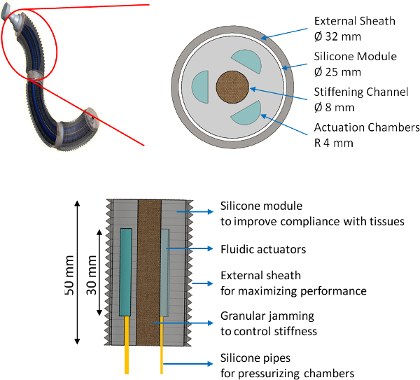
Figure 1. Concept of the manipulator and CAD of the module. The manipulator is based on a multi-module approach. The single unit is constituted by a soft cylinder embedding three fluidic actuators, one central channel housing the granular jamming, three pipes to supply the pressure and an external braided sheath to improve module motion.
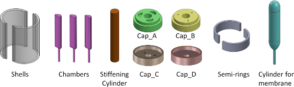
Figure 2. Mold components for the fabrication process. 13 pieces are overall used to assemble molds into which the silicone is poured and to fabricate custom latex membrane.
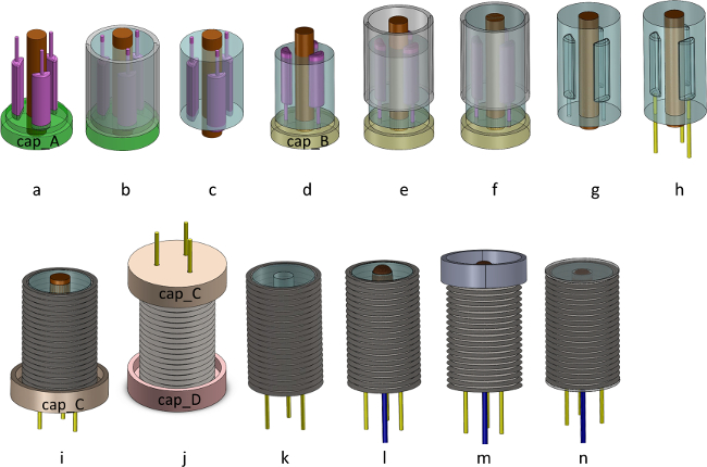
Figure 3. CAD of the fabrication phases. Insertion of the chambers and the stiffening cylinder into cap_A (a), first silicone casting (b), removal of shells and cap_C (c), introduction of cap_B (d), reposition of the shells (e), second silicone casting (f), removal of shells, cap_B and chambers (g), insertion of the tubes (h), insertion of cap_C and sheath for its fixing on the bottom side (i), insertion of cap_D and sheath for its fixing on the top side (j), removal of cap_D and stiffening cylinder (k), insertion of the granular jamming membrane (l), closing of the semi-rings around the module (m), final module (n).
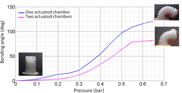
Figure 4. Bending test. Behavior of the module when one chamber is actuated (blue line) and when two chambers are actuated (pink line). Bending angle is indicated on the module in the insets. The range in pressure used for actuating the module goes from 0 bar to 0.65 bar with steps of 0.05. For each position of the module, the bending angle was calculated. This figure has been cited from[19].
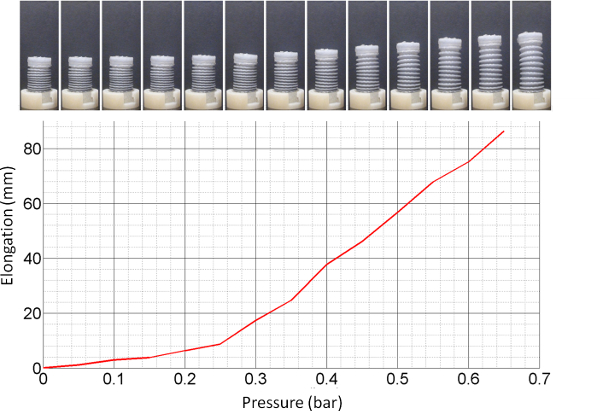
Figure 5. Elongation test. Behavior of the module during the elongation. All three chambers are simultaneously actuated with the same pressure. The pressure range goes from 0 bar to 0.65 bar. For each position the elongation was calculated. This figure has been cited from [19].
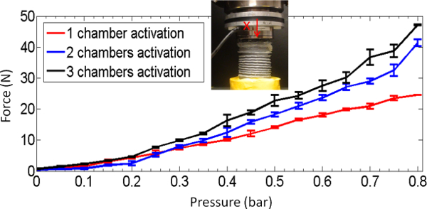
Figure 6. Force test. Evaluation of the force in isometric conditions along x direction. A load cell was positioned on the top of the module and the force was calculated in three different cases relative to the number of actuated chambers. This figure has been cited from[19].
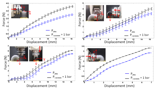
Figure 7. Stiffness test. Evaluation of the stiffness variation in four different configurations when the same chamber is actuated. Different displacements were imposed on the tip of the module using a 6 DoF robot. The stiffness was calculated in the base condition of the module (a) and at 90° bending along y, x and z directions (b, c, d). This figure has been modified from[19].
Mold Component | Number | Description |
Shells | 2 | These have a semi-cylindrical shape, are 40 mm in height, with an internal radius of 12.5 mm and external radius of 14.5 mm. When closed, they form a cylinder that represents the shape of the siliconic unit. The shells are fabricated in polyoxymethylene. |
Chambers | 3 | These chambers represent the negative of the actuation chambers. They have a semi-cylindrical full shape with rounded edges, are 30 mm in height with a 4 mm radius. To facilitate the introduction of the actuation pipelines, at the base of each chamber there is a cylinder with a diameter of 1.5 mm and a length of 13 mm. The chambers are fabricated with a 3D printer machine. |
Stiffening Cylinder (for the granular jamming mechanism | 1 | This is the negative of the stiffening channel. It is 56 mm in height and 8 mm in diameter. It is fabricated in aluminum in order to facilitate its removal from the center of the siliconic cylinder. |
cap_A | 1 | This is a support piece used to fix and align the pieces listed above. It is a disk measuring 10 mm in height, with a diameter of 29 mm for the first 7 mm of height, and 25 mm for the other 3 mm where the external shells close. The top shapes of the chambers are designed inside the second layer, placed at 120°, with a depth of 3 mm in order to insert the top chambers. In the center of the cap, a hole of 8 mm in diameter houses the cylinder of the stiffening channel. |
cap_B | 1 | This support piece is similar to the cap_A, just differs for the second layer which has three holes for the introduction of the cylinders designed at the base of the chambers. |
cap_C and cap_D | 1 each | These supports enable the sheath to be fixed to the module. They have an internal diameter of 35 mm and a central hole of 8 mm in diameter for inserting the stiffening cylinder. Cap_C differs from cap_D because it has 3 holes of 2 mm in diameter to enable the pipes to be inserted. |
Semi-rings | 2 | They have an internal diameter of 30 mm and a height of 10 mm. They are made of aluminum. They are used in the last phase of the fabrication to close the module definitively. |
Cylinder for Membrane | 1 | It is used for the fabrication of a custom membrane for the granular jamming mechanism. It is 50 mm in height and 15 mm in diameter, and has rounded extremities to obtain a convenient shape for the membrane to be introduced into the module. At the base, one thin cylindrical part fixes the mold onto a support during the membrane fabrication. |
Table 1. Mold Components.
The technique described in this protocol enables the fabrication of a pneumatically actuated soft unit usable for modular compliant structures. Thanks to the design of the molds and their simple assembly, it is possible to fabricate one complete module in about 4 hours with 7 main steps. The process of fabrication involves specific materials, which are easily available, and work should be carried out under a fume hood. An external set up including air valves, air compressor and vacuum pump is necessary to activate the module motion and stiffening.
For the fabrication of the soft unit, several elastomeric materials were mechanically tested in order to choose the most suitable for the specific application. Silicone was selected for its high flexibility, low hysteresis, and easy molding.
The fabrication process is based on simple steps, however various critical aspects should be discussed. The fabrication of the crimped braided sheath, reported in Section 4 of the protocol, starts from a commercial braided sheath in polyester with an internal diameter of 32 mm. The dimensions of the metallic cylinder, used for crimping, have to ensure the right development of the crimps, the necessary space to insert the module (inner diameter) and the sufficient distance between the crimps. These features enable the module to work correctly when the chambers are inflated: the sheath has the function to limit the radial expansion of the silicone when the chambers are inflated, avoiding the “balloon effect” of the chambers. Close crimps improve the expansion of the silicone along the motion direction optimizing the bending and the elongation movements. In addition, particular care is needed when heating the sheath in order to prevent overheating, which can degrade the material.
Considering the fabrication and the insertion of the granular jamming membrane (step 6 in the protocol), the filter on the tip of the vacuum tube is necessary to prevent dispersion of the granular material inside the fluidic system. At the moment, the filter consists of a nylon tissue. However, a miniaturized commercial filter could make the vacuum activation safer. The current membrane used for the granular jamming is made of latex. This material ensures a good level of stiffness when the vacuum is applied. However, this requires more attention: the latex inhibits the polymerization of platinum-catalyzed silicone on the top and bottom of the module. The siliconic glue, mentioned in Section 7.7, fixes the membrane and also isolates the latex from the silicone at the extremity of the module, thus the final polymerizations are guaranteed.
Multiple units can be integrated in order to obtain a multi-module manipulator. Preliminary research demonstrates the possibility of connecting three modules20, 21 with a functionally modular architecture where each module replicates the same functionalities. However this integration is limited to a maximum of 3 or 4 modules, due to the method of passing the tubes inside the chambers. This method reduces the available space, thus limiting the multi-module approach to a low number of modules.
Future work will focus on integrating on-board valves, thus enhancing the modularity. The same fabrication technique can be used to produce miniaturized modules (quantities should scale accordingly), however the performance decay has not yet been evaluated. The list of materials used, could be further modified to meet more stringent biocompatibility requirements.
The authors have nothing to disclose.
This work was supported by the EC within the framework of the STIFF-FLOP FP7-ICT-2011.2.1 European Project (#287728).
Ecoflex 00-50 Trial Kit | SmoothOn | Used for the fabrication of the soft unit, combining equal amounts of liquid parts A (the base) and B (the catalyst) | |
Latex | Antichità Belsito | Used for the fabrication of the granular jamming membrane | |
Peroxide-Cured Silicone Tubing | Cole Parmer | T-06411-59 | Used for actuating the chambers and applying vacuum |
PET expandable braided sleeving | RS | 408-249 | Used for the fabrication of the external braided sheath |
Silicone Rubber | Momentive | 127374 | Used to fix the actuation tubes to the module |
Parafilm | Cole Parmer | EW-06720-40 | Used to fix the latex membrane to the vacuum tube |
Fume hood Secuflow | Groupe Waldner | Working space | |
Precision scale | KERN EW | Used to weight silicone, latex and coffee powder | |
Oven/degasser | Heraeus | Used to degass the silicone and reduce its cure time | |
Vacuum pump | DVP Vacuum Technology | Used to apply vacuum to the latex membrane |