We present a robust protocol on how to carefully preserve and prepare cadaveric femora for fracture testing and quantitative computed tomography imaging. The method provides precise control over input conditions for the purpose of determining relationships between bone mineral density, fracture strength, and defining finite element model geometry and properties.
Cadaveric fracture testing is routinely used to understand factors that affect proximal femur strength. Because ex vivo biological tissues are prone to lose their mechanical properties over time, specimen preparation for experimental testing must be performed carefully to obtain reliable results that represent in vivo conditions. For that reason, we designed a protocol and a set of fixtures to prepare the femoral specimens such that their mechanical properties experienced minimal changes. The femora were kept in a frozen state except during preparation steps and mechanical testing. The relevant clinical measures of total hip and femoral neck bone mineral density (BMD) were obtained with a clinical dual X-ray absorptiometry (DXA) bone densitometer, and the 3D geometry and distribution of bone mineral were obtained using CT with a calibration phantom for quantitative estimations based on the greyscale values. Any possible bone disease, fracture, or the presence of implants or artifacts affecting the bone structure, was ruled out with X-ray scans. For preparation, all bones were carefully cleaned of excess soft tissue, and were cut and potted at the internal rotation angle of interest. A cutting fixture allowed the distal end of the bone to be cut off leaving the proximal femur at a desired length. To allow positioning of the femoral neck at prescribed angles during later CT scanning and mechanical testing, the proximal femoral shafts were potted in polymethylmethacrylate (PMMA) using a fixture designed specifically for desired orientations. The data collected from our experiments were then used for validation of quantitative computed tomography (QCT)-based finite element analysis (FEA), as described in a different protocol. In this manuscript, we present the protocol for the precise bone preparation for mechanical testing and subsequent QCT/FEA modeling. The current protocol was successfully applied to prepare about 200 cadaveric femora over a 6-year time period.
Determining the true cadaveric proximal femoral fracture strength with mechanical testing is a destructive method that requires a rigorous testing approach for accurate measurements. In particular, proper bone preparation methods are necessary to maintain near in vivo integrity of the bones prior to mechanical fracture testing1. This is achieved by proper bone storage and minimizing handling at room temperature. This test data is extensively used to validate QCT/FEA models of femoral fracture which have the potential to be used clinically to understand the fracture risk, especially in osteoporotic patients. Unfortunately, there is no current standard procedure to prepare proximal femur samples for mechanical testing. A good testing procedure should ensure repeatability and reproducibility of the preparation process. Therefore, fixtures required for sample preparation need to be carefully designed and fabricated to minimize the likelihood of various testing errors. We also need to minimize the preparation time for which bone tissue is at room temperature and thus in danger of degradation with irreversible changes in mechanical properties.
To this end, we have developed a procedure that preserves bone tissue across multiple preparation steps. This is important to ensure minimal exposure time at room temperature while also minimizing the number of freeze/thaw cycles which can affect tissue physical properties2. The entire procedure is long and nontrivial as the steps occurred over multiple weeks and required scheduling for scanning procedures and personnel availability. The steps included thawing bone samples, screening the samples using DXA scanning to obtain bone mineral density (BMD) values, X-ray to rule out any diseased specimens, and finally CT scanning to estimate distribution of bone mineral and femoral geometry. All the specimens were prepared for testing by removing extraneous soft tissues from the bone surface, cutting the femur to a length required for testing, and potting the femur in a desired orientation for simulating a sideways fall on the hip during subsequent testing. It is essential to keep the time period for all these operations as short as possible. A robust protocol is thus mandatory for consistent specimen preparation, tissue preservation between steps, and for reducing the overall preparation time.
The aim of this paper is to present in detail the procedures involved in the preparation of femoral samples for subsequent mechanical testing under various conditions. Preservation of the bone tissue is crucial in this process and we achieved it by keeping specimens frozen between steps and keeping them carefully wrapped in saline saturated towels at all times except when scanning and mechanically testing the bones. Femora were also kept wrapped in saline wet towels during the steps involving PMMA curing to prevent dryness of the bone tissue.
NOTE: All studies presented in this protocol were approved by the Institutional Review Board (IRB) at Mayo Clinic. The bones were obtained over a period of 6 years from various organizations. All specimens were collected within 72 hours of death, wrapped in saline saturated towels, and stored at -20 °C until preparation.
1. Measuring Bone Mineral Density Using DXA
2. Cleaning, Cutting and Drilling the Distal End of the Bone
3. Potting the Bone
4. Imaging the Bone with X-ray
(CAUTION! Operate with proper care for X-ray radiation when using the machine)
5. CT Scanning of Bones
The cadaveric femora were shipped frozen and maintained at -20 °C until preparation began. BMD scanning was performed using a DXA scanner to measure total hip and neck BMD as well as T-score for each specimen (Figure 1). A T-score is the number of standard deviations of the measured BMD compared to average values for young healthy subjects. It can range from -2.5 or lower for osteoporotic bones, between -1 and -2.5 for osteopenic bones and higher than -1 for normal bones. Once finished, bones were cleaned of excess tissue, and cut to remove the distal end using an in-house designed and fabricated cutting fixture (Figure 2). The specimens were then potted distally using a fixture designed for holding the bones in the desired internal rotation orientation; after placing the distal end into the potting container, the PMMA in liquid form was poured to fill the container (Figure 3). The X-ray images were obtained for paired bones together and for single bones separately to discern the presence of fracture or diseases, such as cancer, that might affect femoral strength (Figure 4). In the presence of such abnormalities, the condition of the bone should be documented when considered for future analyses. Finally, the femora were CT-scanned, in order to obtain CT images, using an acrylic CT scanning fixture designed to hold the bone in appropriate predetermined orientations (adduction and internal rotation angles) (Figure 5). The CT images are used to obtain 3-dimensional bone geometry and volumetric bone mineral distribution to be used in quantitative CT-based finite element analysis. Prior to subsequent fracture testing, all relevant data characterizing each femur such as the BMD values, X-ray images, and CT images were checked to ensure that data of interest were recorded and saved.
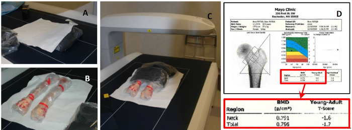
Figure 1: BMD Measurement Using DXA Scanning. (A) Rice bags and plastic lined papers; (B) Two bone specimens in desired orientations in scanner bed; (C) proximal femur ends covered with 2 rice bags during scanning; (D) Neck and total hip BMD measurements with associated T-scores. DXA scanning is performed using a clinical scanner to measure bone mineral density and estimate T-score. Please click here to view a larger version of this figure.
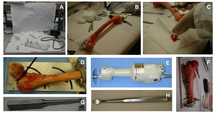
Figure 2: Cleaning and Cutting Bones. (A) Cleaning and cutting desk; (B) bone sample tools for cleaning; (C) cleaning the shaft of a femur; (D) securing a sample in the cutting fixture; (E) cast cutter; (F) completed sample after cutting. A special fixture and bone cleaning and cutting tools are used to prepare the most proximal 255 mm length for testing; (G) curette used for cleaning intramedullary canal of the femur; (H) tool for cleaning superficial tissue in samples. Please click here to view a larger version of this figure.
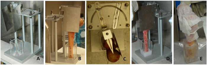
Figure 3: Femur Cleaning and Potting Process. (A) Potting fixture; (B) potting a femur in the fixture; (C) adjusting internal rotation angle to desired value; (D) pouring PMMA in the container; (E) potted bone wrapped in a saline saturated towels. A special fixture is used to set the internal rotation angle to a specified value. Please click here to view a larger version of this figure.
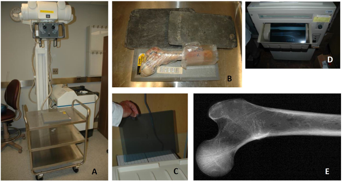
Figure 4: Bone X-ray Process. (A) X-ray machine; (B) bone sample on a cassette with unexposed film, a second half of the cassette is covered by lead to avoid exposure of the entire film; (C) placing unexposed film in loading tray of developer in dark room; (D) developed film; (E) resulting X-ray image of a healthy femur. X-ray equipment is used to scan the bones in two positions to rule out prior fractures, implants, bone metastasis, or any structural abnormalities. Please click here to view a larger version of this figure.
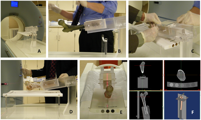
Figure 5: CT Scanning Using an Acrylic Fixture to Hold Bones in a Desired Orientation. (A) CT scanner; (B) fiberglass femur mounted in an acrylic fixture designed to hold bones in a desired orientation; (C) mounting a cadaveric femur in the fixture; (D) vertical alignment of the fixture using the CT long axis laser; (E) Alignment of the femur. An in-house designed fixture is used to hold the bone in a position identical to the subsequent testing position; bone alignment is obtained with the aid of the CT built-in lasers; (F) CT imaging of the femur. Trabecular and cortical bone can be visualized in the CT image. Cortical bone is represented by bright voxels (large Hounsfield Unit (HU) values) surrounding the trabecular bone which is represented by smaller HU values. Note: Care has to be taken to include all five rods and the entire proximal femur in the CT images. Please click here to view a larger version of this figure.
We presented a robust bone preparation protocol for ensuring mechanical testing and QCT/FEA modeling of femoral strength in a sideways fall on the hip configuration. This method became our standard in-house protocol. Over the course of 6 years, with varying personnel, about 200 femora were successfully prepared following this protocol. The outcomes of the protocol includes classifying bone conditions using DXA, ruling out metastatic diseases, previous fractures, or implants using X-ray, and obtaining mineral distribution and 3D geometry using CT for subsequent QCT/FEA modeling. Cutting, potting, and scanning fixtures were designed to accommodate left and right femora as well as for different bone orientations required for future testing, modeling, and analysis. The in-house fixtures assured repeatability and reproducibility of test samples.
Due to the complexity of bone experiments and the need for the combination of BMD, X-ray, and CT scanning before mechanical testing, femora must undergo multiple freeze/thaw cycles. With a proper protocol that minimizes the exposure to room temperature, freezing bone specimens preserves the tissue for mechanical testing, even long term3,4. Previous studies showed that freezing bones at -20 °C does not alter their mechanical properties and that a few freeze/thaw cycles before testing is considered a safe and feasible process5,6. In our study, all femora experienced three freeze/thaw sequences at -20 °C and room temperature, respectively, for DXA scanning, CT scanning, and mechanical testing.
In line with several previous studies, standardized rice bags were used while measuring BMD values of specimens using DXA to mimic in vivo soft tissue around bone7. We compared BMD values of our cadaveric cohort with BMD values of different patient populations and found their distributions to be very similar, suggesting the robustness of our protocol for BMD measurements8.
Femoral samples lack flat surfaces to be easily and properly aligned to a desired orientation for testing. If not done properly, this may impact the repeatability of the procedure and limit the accuracy of the experimental results9. To address this issue, several fixtures were designed and fabricated and standard operating procedures were implemented to make tissue handling independent of the users' skill throughout the sample preparation process. While the femora were acquired and tested over several years, the protocol and the hardware remained the same reducing the potential preparation errors.
One important step of our bone preparation process was to perform CT scanning for 3D modeling of bone fracture using QCT/FEA. Thus, registration between CT scanning and future fracture testing was a necessary step in our femoral sample preparation protocol10.
The current method for bone preparation has some limitations. Although careful planning was implemented during the acquisition of the cadavers, dissection, potting and CT scanning, scheduling the various phases of femur preparation could be challenging due to personnel and equipment availability. Our process requires the specimens to be frozen and thawed at multiple time points. Nevertheless, the freezing time never exceeded more than two weeks, and the bones were subjected to a total of three freeze/thaw cycles. Also the bone preparation process was designed to minimize the operator errors. We observed only one error in potting the distal end of the proximal femur. One right leg femur was potted at the wrong internal rotation angle which, was discovered only after CT imaging. Subsequently, this femur was discarded from further data analysis. Therefore, a second operator might be needed for this step to check on the orientation of the femur before pouring the PMMA for potting. No other errors were observed in any of the other steps. Thus, it is significant to note that our process was very robust allowing for only one error, with multiple operators, during the preparation of about 200 proximal femora in the course of several years.
To provide a good quality control system that will minimize the likelihood of operator errors, certain parts of the protocol need to be repeated or re-checked by a second operator. For example, care should be taken during potting to assure that the femoral shaft is drilled to allow bone cement to enter the femur cavity, guaranteeing that the femur is rigidly fixed and will not loosen during testing. Additionally, potting the femur at the internal rotation angle of interest is usually performed by one operator. Before the PMMA is poured for potting the distal end, a second operator might be required to check that the internal rotation angle was set at the required value. Finally, during CT scanning of the femur, the alignment of the fixture holding the bone on the CT scanner bed is critical. One operator should precisely align the fixture with the CT-laser beams and a second operator should confirm that the fixture is properly aligned.
While the current protocol was designed specifically for fracture testing and modeling of femoral specimens in a sideways fall on the hip configuration, it can be easily extended to other loading scenarios including non-destructive testing, or adopted to test other bone types with appropriate fixture redesign.
The authors have nothing to disclose.
We would like to thank the Materials and Structural Testing Core Facility at Mayo Clinic for technical support. In addition we would like to thank Lawrence J. Berglund, Brant Newman, Jorn op den Buijs, Ph.D., for their help during the study. This study was financially supported by the Grainger Innovation Fund from the Grainger Foundation.
CT potting container and scanning fixture | Internally manufactured | N/A | Custom designed and manufactured |
CT scanner | Siemens | Somatom Definition scanner (Siemens, Malvern, PA) | CT scanning equipment |
Quantitative CT Phantom | Midways Inc, San Francisco, CA | Model 3 CT calibration Phantom | Used for obtaining BMD values from Hounsfield units in the CT image |
Dual Energy X-ray Absorptiometry scanner | General Electric | N/A | GE Lunar iDXA scanner for bone health or any similar BMD scanners |
Hygenic Orhodontic Resin (PMMA) | Patterson Dental Supply | H02252 | Controlled substance and can be purchased with proper approval |
Freezer | Kenmore | N/A | This is a -20oC storage for bones |
X-ray scanner | General Electric | 46-270615P1 | X-ray imaging equipment. |
X-ray films | Kodak | N/A | Used to display x-ray images |
X-ray developer | Kodak X-Omatic | M35A X-OMAT | Used for developing X-ray images |
X-ray Cassette | Kodak X-Omatic | N/A | Used for holding x-ray films |
5-pound Rice Bags | Great Value | N/A | Used for mimicking soft tissue during the DXA scanning process |
Physiologic Saline (0.9% Sodium Chloride) | Baxter | NDC 0338-0048-04 | Used for keeping samples hydrated |
Scalpels and scrapers | Bard-Parker | N/A | Used to clean the bone from soft tissue |
Cast cutter | Stryker | 810-BD001 | Used to cut femoral shaft |
Drilling machine | Bosch | N/A | Used to drill the femoral shaft |
Fume Hood | Hamilton | 70532 | Used for ventilation when using making PMMA |