1. Tweezers Setup
- The beam from a 1064 nm laser is split into two orthogonally polarized beams. One is used to manipulate the biomolecule while the other is used for calibration purposes (see Fig. 2).
- The intensity of the manipulation beam is controlled by an acousto-optic deflector (AOD), while the position and focus of each beam is independently controlled by beam steering mirrors and optical telescopes, respectively.
- The beams are then recombined with another polarizing beam splitter and conditioned further by a final set of telescoping optics to slightly overfill the back aperture of the microscope objective. A 50% overfill for the calibration beam leads to a tight optical trap, while a slightly smaller factor for the manipulation beam, approximately 20%, gives a shallower focus that translates into a larger workable region of the linear potential. The beams are tightly focused by a PlanApo 60x/1.4 oil immersion microscope objective onto the sample cell.
- This tweezers setup is combined with a home built brightfield microscope that provides illumination from a Halogen lamp focused onto the sample chamber by a condenser. The brightfield image is separated from the laser light by a dichroic mirror and then imaged on two CCD cameras. One CCD acts as our primary means of acquiring data and is software triggered to yield precise sampling rates, while the other CCD is used to image a single stuck reference microsphere whose position serves as a feedback-control system to compensate for drift in the microscope.
- The sample is coarsely positioned with respect to the objective by an XY stage, and can then be precisely positioned by an embedded three dimensional piezo-stage.
- The forward-scattered and transmitted laser light is collected by the brightfield condenser and focused onto a photodetector. The resulting signal is filtered through an anti-aliasing filter at 100 kHz, amplified and acquired at 200 kHz using a DAQ card.
2. Calibrating Apparent Size of the Bead to Axial Position
- Load a sample chamber9 with a disperse solution of 800 nm diameter polystyrene microspheres diluted in phosphate buffered saline . Let sit for 10-15 minutes and then lightly flush with buffer to remove excess microspheres.
- Locate a microsphere randomly stuck to the coverglass and adjust the height of the sample chamber until the microsphere is approximately 1 μm below the focus to generate a defocused image.
- To measure the apparent size of the image, first find the centre of the microsphere using the geometric pattern matching function in LabView.
- Next, generate a radial intensity profile of the microsphere by averaging 360° about the center of each cross section. The radial profile, which corresponds to a white ring in each of the brightfield images, can be fitted with a quadratic function to find a brightness peak. The distance between this peak and the center can be used as a measure of the apparent size of the bead.
- Using the calibrated piezostage, gradually increase the axial position of the microsphere and acquire an image at each axial position with the CCD camera.
- Repeat the image analysis for each successive image to correlate the apparent size of the microsphere with its axial location (see Fig. 3). The axial resolution obtained by method is around 1.4 nm7.
3. Mapping the Optical Potential of the Manipulation Beam
- Begin by collinearly aligning the manipulation beam and the calibration beam. The calibration beam should be around 50 mW at the back aperture of the objective while the manipulation beam should be much weaker, say 10 mW.
- With the manipulation beam switched off, confine a free microsphere within the much stiffer trap of the calibration beam.
- Now, turn on the manipulation beam. Since the manipulation beam is much weaker than the calibration beam, the axial position of the microsphere will be slightly perturbed. The resulting change in axial position can be measured from the defocused brightfield images as already described.
- Turn off the manipulation beam and with the microsphere still trapped in the calibration beam, shift the axial focus of the calibration beam by adjusting the telescopic lens. Turn on the manipulation beam, measure the subsequent displacement of the microsphere and repeat.
- The displacements ΔX can be plotted against the axial position of the focus of the calibration beam. The axial position corresponding to the largest displacement of the microsphere determines the center of the linear region of the optical trap (see Fig. 4).
- The final step in obtaining the optical force of the manipulation beam as a function of axial position requires a careful measurement of the stiffness of the calibration beam. To obtain this, move the microsphere, trapped by the calibration beam, to around a micrometer above the surface by adjusting the telescopic lens while the manipulation beam is switched off.
- Record the thermal axial motion of the microsphere by measuring the intensity of transmitted light with a photodetector.
- The autocorrelation of the signal can be fitted to a single exponential decay function to give the time constant of the fluctuations, .τz
- The hydrodynamic friction coefficient ζ, of the microsphere can be corrected for the microspheres proximity to a surface5,10 . The stiffness of the calibration trap is then given by κz = ζ / τz (see Supplementary Materials A and B).
- Knowing the stiffness of the calibration trap allows one to convert the previously measured axial displacements into a force ƒz =κz ΔX Integration of this curve yields a spatial mapping of the axial optical potential of the manipulation beam (see Fig. 4).
4. Stretching a DNA Sample
- Mount the chamber9 containing surface tethered DNA molecules (< 1 kbp) and, while observing the brightfield image, place the focus of the manipulation beam slightly above the unstretched microspheres by adjusting the telescope. Then adjust the position of the stage until one of the microspheres is trapped.
- Roughly position the microsphere in the center of the XY plane of the optical trap. Generate a series of square waves in LabView and send them to the AOD to repetitively turn the laser beam on and off. Carefully control the intensity of the laser and the duration of the on state to prevent heating of the sample chamber. Typically, use around 2 mW of laser power (measured at the back aperture of the objective) and send pulses of 200 ms (on) and 500 ms (off). The amplitude of the square wave sent to the AOD should be around 0.5 V.
- Watch the microsphere as the trap is repeatedly turned on and off and note if the laser induces any preferential direction to the microsphere’s motion. While iteratively adjusting the microsphere position in both the X and Y direction, by controlling the piezostage, the random motion of the microsphere should become isotropic in the XY plane, though noticeably restricted when the laser is on.
- Next, align the bead in the Z direction. Again pulse the laser beam on and off while, this time, simultaneously measuring the microspheres axial displacement in real time. Center the stage within the linear region, which is the point where the Z displacement is greatest.
- After a careful alignment in the Z direction, it is imperative to check that the trap is still centered in the XY plane. If the XY alignment has changed, both the XY and Z alignment must be repeated until the microsphere is centered properly along all three axes.
- For stretching the DNA, ramp the laser intensity by sending a voltage signal to the AOD, from 0 V to 0.5 V in steps of 0.025 V. In each step, record 400 frames at 100 fps and average them to obtain the axial displacement.
- The force extension curves can now be plotted and fit to a modified WLC model11 (see Supplementary Materials B).
5. Representative Results:
We present force extension curves for two DNA sequences: a 1298 bp and a 247 bp sequence, the latter being the shortest sequence we have been able to stretch reproducibly. For short stretches of DNA, the conventional Worm-Like Chain (WLC) model does not fully explain the force extension relationship because at these length scales one must account for finite-size effects and zero force extension arising from boundary constraints. The force extension measurements, therefore, have to be fit using a modified WLC model which has an effective persistence length and a zero force extension as fit parameters, described further in the supplementary materials. For large contour lengths of dsDNA, the effective persistence length is simply the nominal persistence length (˜50 nm) and the zero force extension can be neglected. However, as the contour length becomes shorter the effective persistence length decreases well below 50 nm and the DNA, even under zero force, shows a significant extension.
The data and the corresponding fits of the force extension curves are shown in Fig. 5 for the two sequences. From the modified WLC fits, we have determined the effective persistence lengths to be 35 nm for the 1298 bp DNA and 25 nm for 247 bp DNA. For illustrative purposes, we are presenting single measures of the force extension curves for each sequence. In practice, one would repeat the measurements multiple times and obtain the average results along with the standard errors. It must also be noted that after obtaining each curve it is imperative to ensure that the microsphere remains trapped and properly positioned within the linear region, otherwise the microsphere must be realigned as previously described in the protocol.
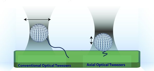
Figure 1 Principle of Axial Optical Tweezers. (Left) Conventional optical tweezers trap near the focus. The bead is then moved lateral to the coverslip to exert tension. (Right) In axial optical tweezers, a microsphere is trapped away from the focus, in the linear region of the optical potential. In this configuration, the polymer is held under constant tension for a range of extensions. Moreover, increasing the laser intensity moves the microsphere in the axial direction.
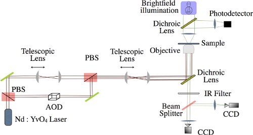
Figure 2 Schematic Representation of Axial Optical Tweezers. Laser light (1064nm Nd:YvO4) is split into two beams by passing through a polarizing beam splitter (PBS). The manipulation beam, passes through an acousto-optical deflector (AOD) and the calibration beam can be adjusted independently using telescopic lenses. The two beams are then recombined using another PBS and focused onto the sample by a high N.A. objective. Simultaneously, brightfield illumination used to track the microsphere,passes through the sample, is infrared (IR) filtered and is then imaged by two CCD cameras, one of which takes measurements while the other acts as part of a feedback control system.
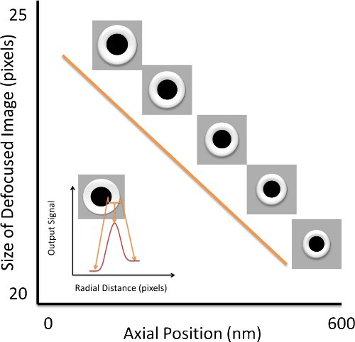
Figure 3 Axial Position Calibration. To calibrate the axial position, we acquire defocused images of a bead stuck to the chamber coverslip at varying axial positions of the stage. The size of the microsphere is given by the distance between its center and the position of peak intensity about the bright ring formed around the image of the microsphere. The inset presents the radial intensity distribution which gives the size of the bead.
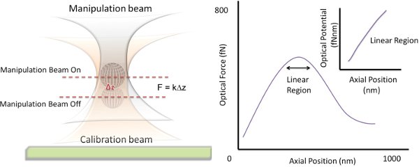
Figure 4 Principle Behind Mapping the Optical Potential. To map out the optical force of the manipulation beam, the axial displacement that it induces on a microsphere trapped within a much stronger calibration beam is measured. The center of the linear region where this displacement is a maximum is located. The Optical Force vs. Axial Position curve can be integrated to find the optical potential.
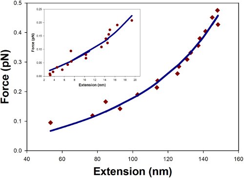
Figure 5 Force Extension Curve. Data is shown for a random 1298 bp and 247 bp (inset) segment of dsDNA stretched by axial optical tweezers. The data points were fit to the modified WLC model of Eq. 3 (solid lines) and yielded effective persistence lengths of 34 nm and 25 nm for the 1298bp and 247bp respectively.
| Reagent/Equipment | Company | Catalog number | Comments |
|---|---|---|---|
| Nd:YVO4 laser | Spectra Physics | T40-Z-106C | |
| Acousto-optic deflector |
IntraAction | DTD-274HA6 | |
| Microscope Objective | Olympus | PlanApo | 60X, NA 1.4 |
| Piezo stage | Mad City Labs | Nano-LP100 | XYZ stage |
| CCD camera | PixeLink | PL-A741 | |
| Photodetector | Electro-Optics Tech |
ET-3020 | |
| Polystyrene Beads | Spherotech | SVP-08-10 | 800nm, streptavidin coated |
| Anti-digoxigenin | Roche | 11333089001 | From sheep |
| Primers | MWG operon | Custom oligos | One primer: biotin Other : digoxigenin |
| PCR reagents | New England Biolabs |
TAQ polymerase, dNTPs |
|
| Coverglass | Fisher Scientific | ||
| Other chemicals for buffer |
Fisher Scientific |
Supplementary Materials
A. Hydrodynamic Friction Coefficient
For determining the hydrodynamic friction coefficient of the microsphere near a surface one can use the following expansion5,10:

where the following shorthand has been introduced:

The friction coefficient is defined in terms of the fluid viscosity η and the radius of the microsphere, with the microsphere’s center located a distance η above the surface. The summation converges reasonably well when expanded to about ten terms.
B. Influence of Axial Position on Stiffness Calibration
The calibration of the trap stiffness involves a tradeoff between the accuracy of the calibration, which increases with increasing distance from the surface, and the actual axial position where the trap is used experimentally. In general, the trap is calibrated at around 800-1000 nm from the surface, which is higher than the actual experimental condition.
C. Modified Worm-Like Chain (WLC) Model
The force extension curves can be fit to a modified WLC model that accounts for volume exclusion effects at zero optical force as follows:

where Fopt is the optical force, xo is a fit parameter for the zero force extension,xopt is the extension under force, l is the contour length of the DNA, and l*p is a second fit parameter for an “effective” persistence length. Fwlc is given by the usual WLC model11

where ε is the relative DNA extension.
