Summary

碳纳米管森林精密铣床使用低压扫描电子显微镜

Published: February 05, 2017
doi:

Summary

Low pressure scanning electron microscopy in a water vapor ambient is used to machine nanoscale to microscale features in carbon nanotube forests.

Abstract

A nanoscale fabrication technique appropriate for milling carbon nanotube (CNT) forests is described. The technique utilizes an environmental scanning electron microscope (ESEM) operating with a low pressure water vapor ambient. In this technique, a portion of the electron beam interacts with the water vapor in the vicinity of the CNT sample, dissociating the water molecules into hydroxyl radicals and other species by radiolysis. The remainder of the electron beam interacts with the CNT forest sample, making it susceptible to oxidation from the chemical products of radiolysis. This technique may be used to trim a selected region of an individual CNT, or it may be used to remove hundreds of cubic microns of material by adjusting ESEM parameters. The machining resolution is similar to the imaging resolution of the ESEM itself. The technique produces only small quantities of carbon residue along the boundaries of the cutting zone, with minimal effect on the native structural morphology of the CNT forest.

Introduction

碳纳米管(CNT)和石墨烯是基于碳的纳米材料已经引起因其优越的强度,耐用性,热和电性能显著关注。碳纳米材料的精密加工成为一个新兴的研究课题,并提供给设计并朝各种工程应用操纵这些材料的潜力。加工碳纳米管和石墨烯需要纳米级的空间精度首先定位感兴趣的纳米区域,然后以选择性的感兴趣的区域内仅去除材料。作为一个例子,考虑垂直取向的碳纳米管林的加工(也称为碳纳米管阵列)。碳纳米管林的横截面可以通过催化剂膜的光刻图案形成精确限定。的垂直取向的森林的顶面,但是,经常具有非均匀的高度有序很差。对于表面敏感的应用,如热界面材料,叔他不规则表面可能会阻碍最佳表面接触并降低器件的性能。不规则表面以产生均匀的平坦表面的精度微调可以通过最大化可用的接触面积可能提供更好,更可重复的性能。

纳米材料的精密加工技术经常不象传统的宏观机械加工技术,例如钻孔,铣削和抛光由硬化模具的装置。迄今为止,使用能束技术已经最成功的碳纳米部位选择性铣削。这些技术包括激光,电子束和聚焦离子束(FIB)照射。这些中,激光加工技术提供了最快速的材料去除速率1,2;然而,激光系统的光点尺寸是许多微米的量级和过大以分离纳米级实体,例如一个碳Ñ一个人口稠密的林内anotube段。与此相反,电子和离子束系统产生可以聚焦到一个点是几纳米或更小直径的光束。

FIB系统是专门为纳米级铣削和材料沉积而设计的。这些系统利用气态金属离子的能量束(通常为镓)以从选定的区域溅射材料。 CNT的FIB研磨是可以实现的,但常常有意想不到的副产物,包括在围绕森林3,4的区域镓和碳的再沉积。当该技术被用于CNT森林,再沉积材料掩模和/或改变选择的研磨区域的形态,改变该CNT森林的天然外观和行为。镓也可以在CNT内植入,提供电子掺杂。这样的后果往往使基于FIB铣削望而却步CNT的森林。

<p class="“jove_content”">透射电子显微镜(电信设备制造商)利用电子的精密聚焦束来探测的材料的内部结构。透射电镜操作加速电压范围一般为80-300千伏。由于碳纳米管的连锁能量为86.4千电子伏5,通过TEM产生的电子能量足以直接从CNT晶格删除原子和诱导高度本地化的铣削。该技术钢厂碳纳米管具有潜在亚纳米精度5,6,7;然而,这个过程是很慢的 – 通常需要几分钟到磨机单个的CNT。重要的是,基于TEM-铣削方法需要首先从生长衬底移除并分散在TEM网格进行处理的CNT。其结果是,基于TEM-方法一般不与碳纳米管林铣削,其中碳纳米管必须保持刚性基板上兼容。

CN铣削 ŧ森林通过扫描电子显微镜(中小型企业)也受到了关注。相反,TEM-基础的技术,SEM工具通常无法加速有足够能量的电子传授给直接删除碳原子所需的连锁能量。相反,基于SEM-技术利用在低压的气态氧化剂的存在下的电子束。该电子束有选择地损害该CNT晶格,并且可以离解的气体环境为更反应性物质如H 2 O 2和羟基自由基。水蒸气和氧气是最常见的气体来实现选择性区域蚀刻。因为基于SEM-技术依赖于多步化学处理,大量的加工变量可能影响该方法的研磨速率和精度。先前已观察到增加的加速电压和电子束电流直接增加,因为增加的能量通量的研磨速率,如预期“外部参照”> 11。室压力的效果不太明显。过低的压力从氧化剂的缺乏症,降低研磨速度。此外,气态物质的过度丰富散射的电子束并降低电子通量在铣削区域,也减少了材料去除速率。

估算碳去除率,一种方法类似于由拉西特用于和架12被采用,由此电子与表面附近的前体分子相互作用以产生蚀刻衬底表面反应性物质。从这个模型,蚀刻速率被估计为

方程

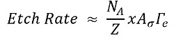
其中N A是蚀刻剂物种的表面浓度,Z是可用的反应位点的表面浓度,x是与挥发性蚀刻化学计量因子相对于反应物生成的产物中,Aσ表示从电子水蒸汽碰撞产生所需的蚀刻物种的概率,并γE是在表面的电子通量。 X和的因素被假定为统一,而Z为假定为几乎恒定并且比NA显著大。进一步的细节可以在我们以前的工作中找到。 11

在这篇文章中,过程进行了探讨,使用低压水蒸汽的SEM内磨区,从个人到碳纳米管体积大(几十立方微米)的材料去除。在这里,我们证明用于使用通过使用减小的面积的矩形,水平行扫描和电子束的软件控制的光栅扫描的ESEM磨碳纳米管林的技术。附加的软件和硬件都需要图案生成,如在材料清单中概述。重点放在相对移除LY大(立方微米的100的)由CNT森林材料体积,所以下面的加工条件相对激进。

当处理样品并把样品存根,它穿一次性腈手套是重要的。这将防止油被传递到存根或样品并因此恶化了泵的效率。

Protocol

1. CNT样品森林铣削的制备 CNT合成 使用原子层沉积13或其它物理气相沉积法的热氧化的硅晶片上沉积氧化铝(矾土)的10纳米。 存款通过溅射14或其他物理蒸镀法铁氧化铝载体层上的1纳米。 合成使用已建立的方法,如热化学气相沉积15的碳纳米管。 加热20毫米直径的管式炉中,以750℃在400标准立方?…

Representative Results

该ESEM技术被用来磨使用热CVD 15,16的CNT林合成。从森林内选定区域去除一些CNT的示于图2 11。对于这个示范,参数包括5千伏,3点尺寸,11帕,170,000X放大率,2毫秒的停留时间,和30微米的孔。 表现出较大规模的区域去除,被选定的CNT森林微柱的顶面进行?…

Discussion

协议细节的最佳实践铣削比较大的(微米级)酒店在CNT森林。在一般情况下,材料移除速率可以通过降低加速电压,光斑尺寸以及孔直径被减小。到一个森林内修剪特定的CNT,推荐的条件包括5千伏,为3的光斑尺寸,和孔径是50微米或更小的直径。注意,使用减少了面积的矩形的研磨技术中详细说明,使得电子束栅格封闭区域仅一次。如果附加的切削深度需要降低的区域可被扫描多次;然而,我们?…

Disclosures

The authors have nothing to disclose.

Acknowledgements

This work was supported by the Air Force Office of Scientific Research grant FA9550-16-1-0011 and University of Missouri startup funds. The authors would like to thank the University of Missouri Electron Microscopy Core facility for assistance with SEM imaging and use of patterning equipment and software.

Materials

100 mm diameter silicon wafer with 1 micron thermal oxide University Wafer Beginning substrate
Iron sputter target Kurt J. Lesker EJTFEXX351A2 Sputter target 
Savannah 200 Cambridge For atomic layer deposition of alumina
Quanta 600F Environmental SEM FEI Environmental scanning electron microscope used to support a low-pressure water vapor ambient environment for CNT forest milling
xT Microscope Control software FEI 4.1.7 Control software used on Quanta 600F ESEM
Nanometer Pattern Generation System – Software JC Nabity Lithography Systems Version 9 Software used for electron-beam lithography
Dedicated computer with PCI516 Lithography board Equipment used for electron-beam lithography
DesignCAD software V 21.2 Optional equipment used to generate patterns for electron-beam lithography
E-beam lithography mount Ted Pella 16405 Electron beam lithography mount with a Faraday cup and gold nanoparticles on carbon tape
Picoammeter Keithley 6485 Used with the Faraday cup to quantify beam current
12.7 mm diameter SEM stub Ted Pella 16111 SEM stub
45 degree pin stub holder Ted Pella 15329 Optional equipment used to mill the cross section of a CNT forest

References

  1. Labunov, V., et al. Femtosecond laser modification of an array of vertically aligned carbon nanotubes intercalated with Fe phase nanoparticles. Nanoscale Res Lett. 8 (1), 375-375 (2013).
  2. Lim, K. Y., et al. Laser Pruning of Carbon Nanotubes as a Route to Static and Movable Structures. Adv Mater. 15 (4), 300-303 (2003).
  3. Raghuveer, M. S., et al. Nanomachining carbon nanotubes with ion beams. Appl Phys Lett. 84 (22), 4484-4486 (2004).
  4. Sears, K., Skourtis, C., Atkinson, K., Finn, N., Humphries, W. Focused ion beam milling of carbon nanotube yarns to study the relationship between structure and strength. Carbon. 48 (15), 4450-4456 (2010).
  5. Smith, B. W., Luzzi, D. E. Electron irradiation effects in single wall carbon nanotubes. J Appl Phys. 90 (7), 3509-3515 (2001).
  6. Banhart, F., Li, J., Terrones, M. Cutting Single-Walled Carbon Nanotubes with an Electron Beam: Evidence for Atom Migration Inside Nanotubes. Small. 1 (10), 953-956 (2005).
  7. Krasheninnikov, A. V., Banhart, F., Li, J. X., Foster, A. S., Nieminen, R. M. Stability of carbon nanotubes under electron irradiation: Role of tube diameter and chirality. Phys Rev B. 72 (12), 125428 (2005).
  8. Royall, C. P., Thiel, B. L., Donald, A. M. Radiation damage of water in environmental scanning electron microscopy. J Microsc. 204 (3), 185-195 (2001).
  9. Yuzvinsky, T. D., Fennimore, A. M., Mickelson, W., Esquivias, C., Zettl, A. Precision cutting of nanotubes with a low-energy electron beam. Appl Phys Lett. 86 (5), 053109 (2005).
  10. Liu, P., Arai, F., Fukuda, T. Cutting of carbon nanotubes assisted with oxygen gas inside a scanning electron microscope. Appl Phys Lett. 89 (11), (2006).
  11. Rajabifar, B., et al. Three-dimensional machining of carbon nanotube forests using water-assisted scanning electron microscope processing. Appl Phys Lett. 107 (14), 143102 (2015).
  12. Lassiter, M. G., Rack, P. D. Nanoscale electron beam induced etching: a continuum model that correlates the etch profile to the experimental parameters. Nanotechnology. 19 (45), 455306 (2008).
  13. Amama, P. B., et al. Influence of Alumina Type on the Evolution and Activity of Alumina-Supported Fe Catalysts in Single-Walled Carbon Nanotube Carpet Growth. ACS Nano. 4 (2), 895-904 (2010).
  14. Almkhelfe, H., Carpena-Nunez, J., Back, T. C., Amama, P. B. Gaseous product mixture from Fischer-Tropsch synthesis as an efficient carbon feedstock for low temperature CVD growth of carbon nanotube carpets. Nanoscale. , (2016).
  15. Maschmann, M. R., Ehlert, G. J., Tawfick, S., Hart, A. J., Baur, J. W. Continuum analysis of carbon nanotube array buckling enabled by anisotropic elastic measurements and modeling. Carbon. 66, 377-386 (2014).
  16. Maschmann, M. R., et al. Visualizing Strain Evolution and Coordinated Buckling within CNT Arrays by In Situ Digital Image Correlation. Adv Funct Mater. 22 (22), 4686-4695 (2012).
  17. Abadi, P. P. S. S., Maschmann, M. R., Baur, J. W., Graham, S., Cola, B. A. Deformation response of conformally coated carbon nanotube forests. Nanotechnology. 24 (47), 475707 (2013).
  18. Brieland-Shoultz, A., et al. Scaling the Stiffness, Strength, and Toughness of Ceramic-Coated Nanotube Foams into the Structural Regime. Adv Funct Mater. 24 (36), 5728-5735 (2014).
  19. Maschmann, M. R., Dickinson, B., Ehlert, G. J., Baur, J. W. Force sensitive carbon nanotube arrays for biologically inspired airflow sensing. Smart Mater Struct. 21 (9), 094024 (2012).
  20. Maschmann, M. R., et al. In situ SEM Observation of Column-like and Foam-like CNT Array Nanoindentation. ACS Appl Mater Inter. 3 (3), 648-653 (2011).
  21. Pathak, S., Raney, J. R., Daraio, C. Effect of morphology on the strain recovery of vertically aligned carbon nanotube arrays: An in situ study. Carbon. 63, 303-316 (2013).
  22. Pour Shahid Saeed Abadi, P., Hutchens, S. B., Greer, J. R., Cola, B. A., Graham, S. Effects of morphology on the micro-compression response of carbon nanotube forests. Nanoscale. 4 (11), 3373-3380 (2012).
  23. Maschmann, M. R. Integrated simulation of active carbon nanotube forest growth and mechanical compression. Carbon. 86, 26-37 (2015).
check_url/kr/55149?article_type=t

Play Video

Cite This Article
Brown, J., Davis, B. F., Maschmann, M. R. Precision Milling of Carbon Nanotube Forests Using Low Pressure Scanning Electron Microscopy. J. Vis. Exp. (120), e55149, doi:10.3791/55149 (2017).

View Video