This manuscript describes the zWEDGI (zebrafish Wounding and Entrapment Device for Growth and Imaging), which is a compartmentalized device designed to orient and restrain zebrafish larvae. The design permits tail transection and long-term collection of high-resolution fluorescent microscopy images of wound healing and regeneration.
The zebrafish larva is an important model organism for both developmental biology and wound healing. Further, the zebrafish larva is a valuable system for live high-resolution microscopic imaging of dynamic biological phenomena in space and time with cellular resolution. However, the traditional method of agarose encapsulation for live imaging can impede larval development and tissue regrowth. Therefore, this manuscript describes the zWEDGI (zebrafish Wounding and Entrapment Device for Growth and Imaging), which was designed and fabricated as a functionally compartmentalized device to orient larvae for high-resolution microscopy while permitting caudal fin transection within the device and subsequent unrestrained tail development and re-growth. This device allows for wounding and long-term imaging while maintaining viability. Given that the zWEDGI mold is 3D printed, the customizability of its geometries make it easily modified for diverse zebrafish imaging applications. Furthermore, the zWEDGI offers numerous benefits, such as access to the larva during experimentation for wounding or for the application of reagents, paralleled orientation of multiple larvae for streamlined imaging, and reusability of the device.
The regenerative capacity of zebrafish larvae Danio rerio make them an ideal model organism for examining wound response as well as healing and regrowth1,2,3,4. Access to an array of transgenic zebrafish lines and zebrafish's anatomical transparency further enhance their utility for in vivo studies of wound response events as well as longer-term regenerative processes4. Study of these biological processes using high-resolution time-lapse fluorescence microscopy therefore demands a live imaging zebrafish device that allows for high stability and minimal movement of the zebrafish larva while maintaining viability. It is key that the device allows for effective wounding while healing and regeneration occur unaffected by the device.
The standard live imaging stabilization method of embedding the larva in agarose during live imaging restricts growth and wound regeneration5 and may increase death rates since larvae begin to show sign of cardiac stress and tissue necrosis after four hours4. Therefore, removal of agarose from regions of interest is often necessary to allow normal development and regeneration6, exposing the larvae to potential damage as the agarose is cut away. Furthermore, with the agarose embedding technique, the user must orient the larvae in the short time before the agarose solidifies5,6,7. Rapidly manipulating the larva not only requires skill of the user, it also risks damage to the larva. Although methods to stabilize the larva for live imaging have been described to circumvent these drawbacks, such as ridged agar wells3 or divets8, the use of silicone vacuum grease to create an imaging chamber with PVC piping or other materials6, and rotational tubing9, many of these methods are labor intensive, messy, often non-reusable and don't allow for environmental manipulation (drug treatments, wounding etc.) after the fish has been mounted.
Therefore, the zWEDGI device (Figure 1) was designed to overcome some of the drawbacks of agar mounting for long-term live imaging of zebrafish larvae while permitting manipulation of the specimen. The zWEDGI consists of three semi-open compartmentalized chambers (Figure 1A) to allow for loading, restraint, wounding and imaging of 2 to 4 days post-fertilization zebrafish larvae. The device is fabricated from Polydimethylsiloxane (PDMS) and placed onto the cover slip of a 60 mm glass bottom imaging dish. The design presented here was intended for wound healing studies, however the use of a modular design and standard fabrication technologies make the zWEDGI design modifiable and amenable to a variety of experimental procedures, especially for procedures that require minimal restraint with experimental manipulation and long-term imaging.
Note: The base zWEDGI design was formulated for zebrafish larvae that are 2 to 4 days post-fertilization (dpf) and follow the guidelines of the University of Wisconsin-Madison Research Animals Resource Center.
1. Design and 3D Printing of Molds
2. PDMS Fabrication of zWEDGI Device
3. Plasma-bonding zWEDGI to Glass Dish
4. Channel Preparation and Loading Larvae
Note: General zebrafish husbandry was conducted per The Zebrafish Book, available online at http://zfin.org/zf_info/zfbook/zfbk.html. Adult zebrafish and embryos were maintained as described previously1. The wild type AB strain was used. Follow the institution’s Animal Care Protocol for specifics regarding requirements for imaging live larvae.
5. Wounding and Imaging Larvae
6. End of Experiment
The zWEDGI PDMS microfluidic device is a functionally compartmentalized device designed to accommodate four main functions (listed below) associated with live imaging of caudal fin wounding healing and regrowth in the zebrafish larvae. PDMS was chosen for zWEDGI fabrication because it is not only readily available and an industry standard for biocompatibility, but also works well in molds. Additionally, PDMS makes the device reusable and void of hard or sharp edges once the device is formed. The zWEDGI specifically permits 1) the loading of the larvae into the device, 2) restraint at proper orientation for imaging, 3) wounding of the caudal fin, and 4) microscopic imaging, described in detail below.
Loading
The zWEDGI design consists of 3 channels, each designed to restrain one larva (Figure 1B). For the loading and initial orientation of the larva, the open loading chamber is 3 mm wide (Figure 1A) to accommodate a large orifice pipette tip for depositing a larva (Figure 3A). Further, the length and width provide sufficient room to permit subsequent manipulation of the larva into the correct orientation, with tail toward the restraining tunnel and dorsal side toward the top (Figure 3B).
Restraint
Once the larva has been loaded into the channel, it can be drawn tail-first into the restraining tunnel by removal of fluid from the wounding chamber or gently nudge into place with a pipette tip or similar tool (Figure 3C). The funnel-shaped geometry of the loading chamber (Figure 1A), from 3 mm to 0.45 mm, guides the larva into desired lateral orientation (Figure 3C). The orientation of the larva on its side restrains the tail approximately in parallel with the glass bottom of the dish for improved imaging. Unlike microfluidic devices made using silicon wafers, the geometries of the 3D printed molds need not be consistent in the z-direction. Therefore, the restraining tunnel is covered and tapered in the z-axis such that the entry height is larger than the exit, from 0.5 mm to 0.3 mm height (Figure 1B, isometric view of tunnel). This tapering facilitates guidance of the larva and flattening of the tail toward the cover glass imaging surface. This functionality eliminates the need for the user to orient the specimen while agarose is hardening.
Fluid is removed from the loading chamber (Figure 3D) and is replaced with low melting point agarose to stabilize the head within the channel while the tail is maintained unrestrained in buffer in the wounding chamber (Figure 3E). The minimal agarose that may leak through the restraining tunnel can easily be removed from the wounding chamber (Figure 3F). The lack of agarose in the wounding chamber permits unrestrained regrowth and development of the caudal fin5.
Wounding
Once the larva has been loaded through the tunnel and the head restrained by agarose, the caudal fin is available for transection because it juts out into the wounding chamber. The semi-circle wounding chamber is offset 1.9 mm from horizontal symmetry. This permits the scalpel blade to be inserted just above the caudal fin, allowing sufficient space for the blade to be drawn downward across the tail, transecting the caudal fin (Figure 3G). The widest portion of the 7 mm diameter semi-circle occurs where the tail is wounded to accommodate this motion. In addition to allowing the user to wound the larva, this compartmentalized design provides the opportunity for regional application of compounds to the tail region5. This unique feature of semi-isolation would allow for localized testing of the effects of various drugs, chemicals, or biological agents on the wound healing process.
Imaging
The goal of the zWEDGI device is to permit high resolution light microscopy imaging of the zebrafish caudal fin, unimpeded by agarose embedding. For this reason, the PDMS device is bonded to a commercially available glass bottom dish, to provide an optical quality surface for microscopy using high NA lenses. Here we present images using multiphoton microscopy for second harmonic (SHG) imaging of collagen fibers in the caudal fin to illustrate the imaging capabilities of the zWEDGI. However, the zWEDGI can be applied to other light microscopy methods, such as confocal microscopy, utilizing an inverted microscope stage configuration. With the zWEDGI, unlike the method of agarose embedding with subsequent removal, the caudal fin can easily be imaged in the device prior to wounding (Figure 4A), wounded within the device, then immediately returned to the microscope for post-wound imaging (Figure 4B-E). Previous work identified changes in the collagen fiber organization during the wound healing process using SHG.13 SHG can be used to detect certain types of ordered structures, including fibrillar collagen, without the use of exogenous labels.14 Image quality of the living caudal fins imaged in the zWEDGI was similar to that obtained in fixed tissue5 but the zWEDGI provides a number of advantages. Most importantly, the caudal fin healing and regrowth can proceed unhindered by agarose embedding with larval survival similar to that of larvae grown unrestrained5. Further, because the wounding can be performed while the larva is in the device, pre- and post-wounding images can be collected on the same caudal fin (Figure 4A). The zWEDGI permits the collection of 3 dimensional data over time, providing a more complete view of the dynamic changes occurring in the structure of the extracellular matrix (Figure 4B). Illustrated here is the SHG fiber wound relaxation, in 3 dimensions, following wounding within the zWEDGI. Prior to wounding, the SHG detected collagen fibers radiate outward from the notochord to the fin tip, (Figure 4A). Shortly after wounding the distance between tip of the contracted fin and the center of the fin increases with wound relaxation. The 3D nature of the data collection permits the spatial reconstruction, using rendering software such as Imaris. These reconstructions, and the subsequent rotation options, illustrate the contraction and relaxation of the fin occurs not only in the x y plane of the image collection (Figure 4 B, C, D), but also in the z axis (Figure 4 G-J, L-O, Q-T; Supplemental Movies 1, 2) as the tail flattens from the upward curl of the contracted state. The zWEDGI can be used with other imaging modalities over longer time periods, such as the use of confocal microscopy to image neurons during caudal fin development over 24 h5. Because the device's restraining units are lined up parallel, thus eliminating the need to rotate the device when locating the larvae, setting up the microscope and moving between multiple specimen for imaging is straightforward and can be automated to collect time-lapse image data of multiple larvae. To extend the number of samples that can be imaged, the PDMS zWEDGI device can be placed into other glass bottomed formats, such as a 6-well plate (Figure 2C).
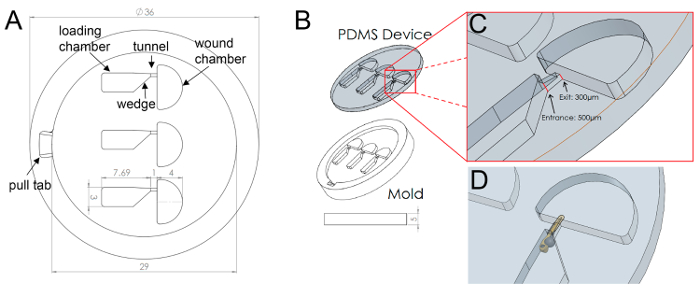
Figure 1: Final Design Schematic (A) Schematic showing general layout and measurements of the zWEDGI device, highlighting terminology of the functionally compartmentalized chambers. (B) Isometric view of PDMS device as removed from mold. (C) Inset shows tunnel, highlighting the change in entrance and exit heights. (D) Model of larva restrained in device. Figure modified from a previously publish article5 with reprint permission from Zebrafish Journal. Please click here to view a larger version of this figure.
Figure 2: Fabrication Schematic (A) Step 1 begins with design of the device mold in a 3D modeling software (1.1) which is then 3D printed (1.2). The molds are UV light cured and then sanded and cleaned so the raised geometries have even height (1.3). Step 2 involves filling the molds with mixed and degassed PDMS (2.1) and applying a glass disc over the mold at a slant to prevent trapping air bubbles in the device PDMS (2.2). The glass and mold are clamped together (2.3) for curing in an oven at 100oC for at least an hour (2.4). Step 3 uses filtered air and flat-tipped tweezers to remove the PDMS device from the mold (3.1). The device is then placed on the top of the imaging dish lid (3.2) and is plasma treated (3.3), along with the glass bottom, to allow the PDMS to adhere to the glass bottom dish (3.4). (B) The finished zWEDGI device bonded in a glass bottom dish and ready for imaging use. (C) Multiple zWEDGI devices can be placed in a glass bottom 6-well plate in order to image many larvae in the same experiment. Figure modified from a previously publish article5 with reprint permission from Zebrafish Journal. Please click here to view a larger version of this figure.
Figure 3: Loading and Wounding of Larva in zWEDGI (A) A larva is loaded into the loading chamber using a wide-orifice pipette. (B) The larva is oriented with the dorsal side up against the flat portion of the loading chamber funnel and tail toward the restraining tunnel. (C) Using suction from the pipette tip held at the entrance to the wounding chamber, the larva is drawn into the tunnel, placing it in proper orientation for imaging. (D) Fluid is removed from the loading chamber to allow for (E) the addition of agarose around the head region to stabilize the larva. Agarose is colored red here for demonstration purposes only. Minimal agarose leaks into the wounding chamber and can be easily removed as shown in (F). (G) To wound once the larva is restrained in the channel, a scalpel blade is inserted above the larva and sliced down across the caudal fin, posterior to the notochord. (H) The larva is now ready for post-wound imaging. Scale bar (A-H) = 1 mm; Scale bar (F) = 1 mm; Scale bar (G) = 1 mm. Figure modified from a previously publish article5 with reprint permission from Zebrafish Journal. Please click here to view a larger version of this figure.
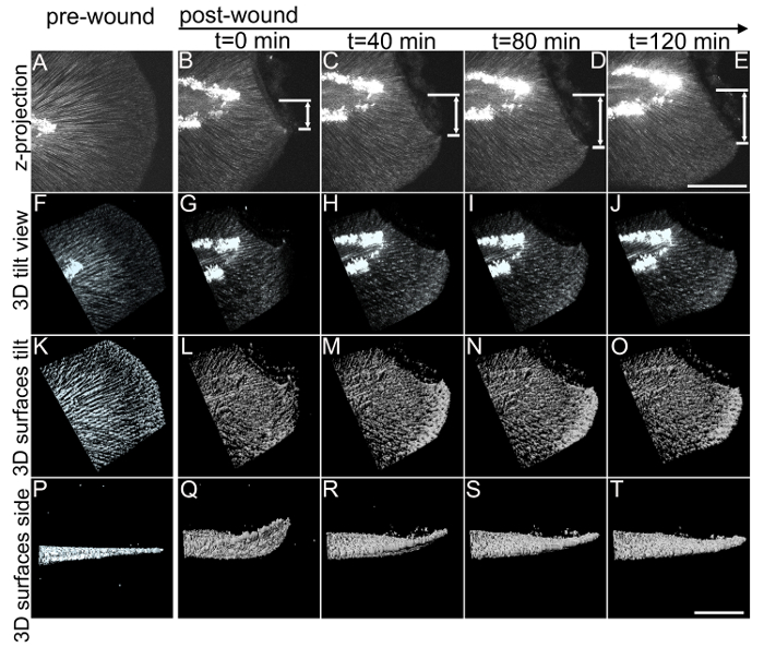
Figure 4: 3D multiphoton time lapse imaging of SHG fibers in the zebrafish caudal fin, pre- and post-wounding, in the zWEDGI. The zWEDGI design provides the ability for high resolution imaging, in this case of SHG fiber organization preceding (pre-wound) and following caudal fin transection (post-wound). Data were collected as z-stacks at 4 min intervals. (A-E) shows the SHG of fibers in the caudal fin as a projection of the z-stacks, prior to and at four intervals post-transection. Z-projection was performed using ImageJ software.15 t = 0 was the start of imaging, approximately 20 min post-transection. The double arrows indicate the increase in distance of the tip of the wound edge (short white line) relative to the location of the notochord (long white line) during relaxation of the wound following the initial contraction. (F-J). Tilted 3D reconstruction of the original data. (K-O). Surface rendering of the tilted 3D reconstruction shown in F-J. (P-T). Side views of the 3D reconstruction surface rendering, illustrating how the contraction and relaxation occur in 3-dimensional space, which can be assessed with this data collected using the zWEDGI where the caudal fin is not constrained by agarose. Scale bar (A-E) = 100 microns; Scale bar (F-T) = 100 microns. 3D renderings were performed using imaging software. See also Supplemental Movies 1 and 2. Figure modified from a previously publish article5 with reprint permission from Zebrafish Journal. Please click here to view a larger version of this figure.
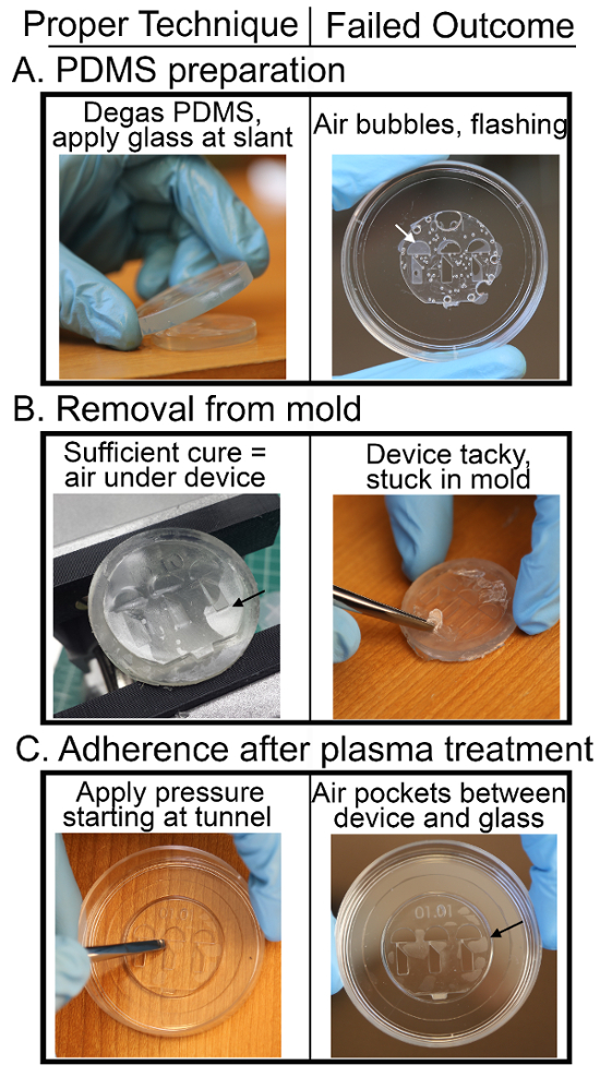
Figure 5: Critical Steps of zWEDGI Fabrication (A) To ensure no bubbles form or get trapped in the device when clamping on the glass disc, degas after PDMS has been filled into the molds and slant the clamping glass when applying it to the PDMS in the mold. In addition, to prevent PDMS from "flashing" over the loading and wounding chambers, make sure to sand the top of the device thoroughly to ensure the surfaces of the geometries are flush when clamping on the glass. (B) When the device is sufficiently cured in the oven, air pockets between the PDMS and mold indicate that the device will be easy to remove. If the device does not remove easily, it is most likely due to insufficient cure time or temperature or the mold itself was not adequately UV-cured, resulting in residual resin contamination of the PDMS. (C) When applying the device to the glass bottom dish after plasma treatment, apply light pressure with the back end of tweezers, starting at the tunnel regions and working outward towards the edge of the device. If the device does not bond well, as indicated by air pockets between the device and the glass, lengthen the amount of time in the plasma bonder and ensure that there is no dust between the PDMS and glass surface. Please click here to view a larger version of this figure.
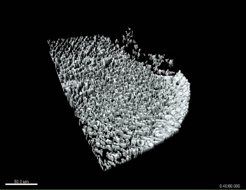
Supplemental Movie 1: Tilted 3D surface rendering of multiphoton time lapse images of SHG fibers in the caudal fin during relaxation post-wounding. The SHG of fibers in the caudal fin imaged as zstacks over time after wounding (start of movie is approximately 20 min after wounding) in the zWEDGI. Z-stacks were reconstructed and surface rendered using imaging software. Tail tilted to show three dimensionality. Anterior is to the left. Movie corresponds to still images in Figure 4 (K-O). Scale bar = 50 microns. Please click here to download the movie.
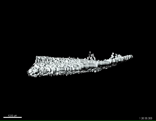
Supplemental Movie 2: Side view of 3D surface rendering of multiphoton time lapse images of SHG fibers in the caudal fin during relaxation post-wounding. The SHG of fibers in the caudal fin imaged as zstacks over time after wounding (start of movie is approximately 20 min after wounding) in the zWEDGI. Z-stacks were reconstructed and surface rendered using imaging software. Side view shown to emphasize the capture of dynamic changes in the z-axis. Anterior is to the left. Movie corresponds to still images in Figure 4 (P-T). Scale bar = 40 microns. Please click here to download the movie.
The purpose of the zWEDGI device is to capture 3D time lapse imaging by stabilizing and orienting the fish within the small working distance of a high-resolution microscope objective. While meeting these design specifications, it is also an improvement over traditional agar-based preparation for live imaging. There are three critical steps (below) in the fabrication of the zWEDGI, which, if not done correctly, can result in defective devices:
PDMS preparation (Figure 5A)
To prevent bubbles, degas the molds after PDMS has been added. Check that all bubbles have been eliminated after degassing and pay careful attention to the application of the glass disc. The glass disc must be applied at a slant to ensure that air is not being trapped beneath and within the PDMS. Dust can be a problem during most steps of the process. To prevent dust, complete each cleaning step thoroughly and store parts in a clean hood between steps. Check molds for excess resin that may create a rough surface prior to UV-curing. When sanding, make sure that the sand paper contacts all geometries to ensure that all surfaces are flush (Figure 2, Step 1.3). Always clean with isopropyl alcohol and air right before filling the molds with PDMS. When squeezing the extra PDMS out of the mold, ensure the clamps tightly hold the mold and glass cover together (Figure 2, Step 2.3).
Removing device from mold (Figure 5B)
Ensure the oven is at least 100 oC and the cure time is at least 1 – 1.5 h. If the PDMS is not sufficiently cured, it can be difficult to remove from the mold. Other possibilities for failure to remove include not mixing the PDMS reagents long enough, using incorrect ratios of base and hardener or leftover resin remaining in the mold after 3D printing which then contaminates the PDMS. Upon removal from the oven, air pockets between the device and mold (Figure 5B) indicate that the device will be easily removed.
Adherence of PDMS to glass-bottomed dish (Figure 5C)
Poor adherence to the glass dish may result from dust, misalignment, or insufficient length of plasma treatment. When placing the device onto the glass, tip the dish at an angle and center the PDMS onto the glass circle making sure it does not touch the edges of the well. If device does not adhere, carefully press the device onto the glass slip with the back end of the tweezers, beginning at the delicate tunnel region and pressing outward to the edges. If the device still does not adhere, experiment by increasing the time in the plasma cleaner in increments of one minute.
While the larvae can be imaged in the device for brief periods of time (minutes) without the use of agar, for the purpose of long-term live-imaging the caudal fin region, agar is placed on the head in the loading chamber after the fish has been loaded. Although this application of agar does not appear to affect the wound healing response or viability of the larvae5, this could impact the study of more anterior regions of the larvae. Although we have been able to image larvae for up to 60 h we have not examined whether viability would be impacted with longer imaging times. Additionally, the particular design presented here was optimized for age 2 to 4 days post fertilization (dpf) larvae lying on their sides for tail transection and wound healing imaging. Other developmental stages, orientations and experimental protocols may require alterations to the design. However, the intentional functional modularity of the design makes it readily amenable to such alterations.
In addition, fabrication of this device requires access to a 3D printer and other microfluidic materials and equipment, such as PDMS and a plasma cleaner, potentially limiting the accessibility of the device to some users. However, this method of mold fabrication was chosen since 3D printing capabilities, along with microfluidics fabrication, are becoming more prevalent on academic campuses. Additionally, there are service providers for 3D printing available, as the technology rapidly develops and the cost of printers decreases.
Given its compartmentalized design and functionality, the zWEDGI offers improvements over the current technique for time lapse image collection using agar embedding. First, agarose does not surround the tail region in the zWEDGI, permitting wound healing and regeneration to progress uninhibited while survival of larvae in the zWEDGI is comparable to embedded and unembedded controls5. Secondly, the use of high-resolution 3D printing to fabricate the molds allows the zWEDGI to have unique sloping geometries to orient the larva in three dimensions with respect to the imaging plane. This removes the time dependency of manipulating the larvae to a proper orientation as the agar hardens. A third important benefit of the zWEDGI design is the open chamber design that permits the tail and head regions to be accessible for experimental manipulation. This is of specific interest for wound healing studies, but this also makes the zWEDGI a potentially useful tool for other manipulations. The compartmental design of the device, furthermore, provides the opportunity for regional application of compounds during experimentation. The device semi-isolates the head from the tail because of the diffusion differential of buffer (in the wounding chamber) and agarose (in the loading chamber)5, allowing application of compounds while studying wound healing or other biological processes. In addition, because the larvae are mounted in separate channels, individual larva can be identified and retrieved post-imaging for additional processing such as RNA or protein purification or antibody labeling. And finally, because the device is made of PDMS that has been bonded to the glass bottomed dish, the device is reusable once the larvae have been removed.
In moving forward, the modular design and ease of fabrication of the zWEDGI will lend itself well to modification for altered functionality. Currently, the compartmental geometries are built specifically for the wounding and imaging experiments described, giving it broad application for live imaging of wound healing. However, the larva lies directly on the glass, such that no material (i.e. PDMS), which might interfere with imaging, exists between the larva and the imaging surface. Therefore, other regions of the larvae, such as the trunk, would be accessible for imaging. In addition, the design of the 3D printed mold of the zWEDGI can readily be modified to accommodate other developmental stages, different orientations of the larva and varied treatments. These attributes therefore make it a valuable tool for capturing time lapse microscopy of events over a variety of time scales. The use of other glass bottom dish formats could allow for larger PDMS devices and space for more channels. Given the increasing accessibility to 3D printing fabrication techniques and the subsequent ease of modification for a variety of experimental protocols, the zWEDGI may prove to be a powerful tool in the realm of high resolution live imaging microscopy.
The authors have nothing to disclose.
The authors would like to acknowledge primary project funding from the Morgridge Institute for Research and the Laboratory for Optical and Computational Instrumentation. We also acknowledge funding from NIH# R01GM102924 (AH and KWE). KH, JMS, RS, AH and KWE conceived and designed the study. KH and JMS performed all experiments with support from DL, KP and RS. KH, JS, RS, AH and KWE contributed to the writing of the manuscript.
Fabricate molds | |||
Solidworks Professional Accedemic Research 3D modeling software | Dassault Systemes | SPX0117-01 | Fisher Unitech |
Viper Si2 SLA 3D printer | 3D Systems Inc. | 23200-902 | 3D Systems Inc. |
Accura 60 photopolymer resin | 3D Systems Inc. | 24075-902 | 3D Systems Inc. |
denatured alcohol | Sunnyside | 5613735 | Menards |
UV post cure apparatus | 3D Systems Inc. | 23363-101-00 | 3D Systems Inc. |
TouchNTuff nitrile gloves | Ansell | 92-600 | McMaster Carr |
220B, 400B, 600 grit T414 blue-bak sandpaper | Norton | 66261139359, 54, 52 | MSC |
borosilicate glass disc, 2" diameter | McMaster-Carr | MIL-G-47033 | McMaster-Carr |
ultrasonicator cleaner | Branson | 1510R-MTH | |
isopropyl rubbing alcohol 70% | Hydrox | 54845T43 | McMaster-Carr |
10oz clear plastic cup | WNA Masterpiece | 557405 | Amazon |
6"craft stick | Perfect Stix | Craft WTD-500 | Amazon |
Name | Company | Catalog Number | Comments |
Fabricate zWEDGI PDMS device | |||
Sylgard 184 silicon elastomeric kit | Dow-Corning | 4019862 | Ellworth Adhesives |
10mL syringe | Becton Dickinson | 305219 | Vitality Medical Inc |
desiccator | Bel-Art Scienceware | F42027-0000 | Amazon |
4 in ratcheting bar clamp | Pittsburgh | 68974 | Harbor Freight |
lab oven | Quincy Lab Inc. | 20GC | Global Industrial |
tweezer set | Aven | 549825 | McMaster-Carr |
compressed air filtered nozzle | Innotech | TA-N2-2000FT | Cleanroom Supply |
vacuum bench vise | Wilton Tool Group | 63500 | MSC Industrial |
55mm glass bottom dish; 30mm micro-well #1.5 cover glass | Cellvis | D60-30-1.5-N | Cellvis |
plasma cleaner | Harrick Plasma | PDC-001 | Harrick Plasma |
Name | Company | Catalog Number | Comments |
Loading Larvae | |||
Pipetteman, P200 | Gilson | F123601 | |
100% ethanol (diluted to 70% with water prior to use) | Pharmco-aaper | 111000200 | |
Transfer pipette | Fisherbrand | 13-711-5A | Fisher Scientific |
powdered skim milk | 2902887 | MP Biomedicals | |
double distilled water | |||
N-phenylthiorurea | Sigma-Aldrich | P7629 | Sigma-Aldrich |
tricaine (ethyl 3-aminobenzoate) | C-FINQ-UE | Western Chemical | |
low melting point agarose | Sigma-Aldrich | A0701 | Sigma-Aldrich |
heat block (dry bath incubator) | Fisher Scientific | 11-718-2 | Fisher Scientific |
E3 buffer | |||
large orifice pipette tip, 200 uL | Fisherbrand | 02-707-134 | Fisher Scientific |
General purpose pipette tip, 200 uL | Fisherbrand | 21-197-8E | Fisher Scientific |
#15 scalpel blade | Feather | 2976 | Amazon |
25G syringe needle | BD | BD305122 | Fisher Scientific |
Name | Company | Catalog Number | Comments |
Imaging | |||
inverted microscope | |||
Imaris imaging software | Bitplane |