Magnetic Resonance Imaging of Multiple Sclerosis at 7.0 Tesla
Summary
Here, we present a protocol to acquire magnetic resonance (MR) images of multiple sclerosis (MS) patient brains at 7.0 Tesla. The protocol includes preparation of the setup including the radio-frequency coils, standardized interview procedures with MS patients, subject positioning in the MR scanner and MR data acquisition.
Abstract
The overall goal of this article is to demonstrate a state-of-the-art ultrahigh field (UHF) magnetic resonance (MR) protocol of the brain at 7.0 Tesla in multiple sclerosis (MS) patients. MS is a chronic inflammatory, demyelinating, neurodegenerative disease that is characterized by white and gray matter lesions. Detection of spatially and temporally disseminated T2-hyperintense lesions by the use of MRI at 1.5 T and 3 T represents a crucial diagnostic tool in clinical practice to establish accurate diagnosis of MS based on the current version of the 2017 McDonald criteria. However, the differentiation of MS lesions from brain white matter lesions of other origins can sometimes be challenging due to their resembling morphology at lower magnetic field strengths (typically 3 T). Ultrahigh field MR (UHF-MR) benefits from increased signal-to-noise ratio and enhanced spatial resolution, both key to superior imaging for more accurate and definitive diagnoses of subtle lesions. Hence, MRI at 7.0 T has shown encouraging results to overcome the challenges of MS differential diagnosis by providing MS-specific neuroimaging markers (e.g., central vein sign, hypointense rim structures and differentiation of MS grey matter lesions). These markers and others can be identified by other MR contrasts other than T1 and T2 (T2*, phase, diffusion) and substantially improve the differentiation of MS lesions from those occurring in other neuroinflammatory conditions such as neuromyelitis optica and Susac syndrome. In this article, we describe our current technical approach to study cerebral white and grey matter lesions in MS patients at 7.0 T using different MR acquisition methods. The up-to-date protocol includes the preparation of the MR setup including the radio-frequency coils customized for UHF-MR, standardized screening, safety and interview procedures with MS patients, patient positioning in the MR scanner and acquisition of dedicated brain scans tailored for examining MS.
Introduction
Multiple sclerosis (MS) is the most common chronic inflammatory and demyelinating disease of the central nervous system (CNS) that causes pronounced neurological disability in younger adults and leads to long term disability1,2. The pathological hallmark of MS is the accumulation of demyelinating lesions that occur in the gray and white matter of the brain and also diffuse neurodegeneration in the entire brain, even in normal-appearing white matter (NAWM)3,4. MS pathology suggests that inflammation drives tissue injury at all stages of the disease, even during the progressive stages of disease5. The first clinical manifestations of MS are commonly accompanied by reversible episodes of neurological deficits and referred to as a clinically isolated syndrome (CIS), when only suggestive of MS6,7. In the absence of a clear-cut CIS, caution should be exercised in making an MS diagnosis: the diagnosis should be confirmed by follow-up and initiation of long-term disease-modifying therapies should be postponed, pending additional evidence8.
Magnetic resonance imaging (MRI) is an indispensable tool in diagnosing MS and monitoring disease progression9,10,11. MRI at magnetic field strengths of 1.5 T and 3 T currently represents a crucial diagnostic tool in clinical practice to detect spin-spin relaxation time weighted (T2) hyperintense lesions and establish accurate diagnosis of MS based on the current version of the 2017 McDonald criteria8. Diagnostic criteria for MS emphasize the need to demonstrate dissemination of lesions in space and time, and to exclude alternative diagnoses8,12. Contrast enhanced MRI is the only method to assess acute disease and acute inflammation8but increasing concerns regarding potential long-term gadolinium brain deposition could potentially restrict contrast application as an important diagnostic tool13,14,17. Additionally, the differentiation of MS lesions from brain white matter lesions of other origins can sometimes be challenging due to their resembling morphology at lower magnetic field strengths.
While MRI is certainly the best diagnostic tool for MS patients, MR examinations and protocols should follow guidelines of the Magnetic Resonance Imaging in MS group (MAGNIMS) in Europe18,19 or the Consortium of Multiple Sclerosis Centers (CMSC) in North America20 for the diagnosis, prognosis and monitoring of MS patients. Standardized quality control studies in accordance with the latest guidelines across different hospitals and countries are also crucial21.
MRI protocols tailored for MS diagnosis and disease progression monitoring comprise multiple MRI contrasts including contrast governed by the longitudinal relaxation time T1, the spin-spin relaxation time T2, the effective spin-spin relaxation time T2*, and diffusion weighted imaging (DWI)22. Harmonization initiatives provided consensus reports for MRI in MS to move towards standardized protocols that facilitate clinical translation and comparison of data across sites23,24,25. T2-weighted imaging is well established and frequently used in clinical practice for identification of white matter (WM) lesions, which are characterized by hyperintense appearance26,27. While being an important diagnostic criterion for MS28, the WM lesion load correlates only weakly with clinical disability, due to its lack of specificity for lesion severity and the underlying pathophysiology26,27,29. This observation has triggered explorations into parametric mapping of the transverse relaxation time T2 30. T2*-weighted imaging has become increasingly important in imaging MS. The central vein sign in T2* weighted MRI is considered to be a specific imaging marker for MS lesions27,31,32,33. T2* is sensitive to iron deposition34,35, which may relate to disease duration, activity and severity36,37,38. T2* was also reported to reflect brain tissue changes in patients with minor deficits and early MS, and thus may become a tool to assess the development of MS already at an early stage39,40.
Improvements in MRI technology promise to better identify changes in the CNS of MS patients and to provide clinicians with a better guide to enhance the accuracy and speed of an MS diagnosis11. Ultrahigh field (UHF, B0≥7.0 T) MRI benefits from an increase in signal-to-noise ratio (SNR) that can be invested in enhanced spatial or temporal resolutions, both key to superior imaging for more accurate and definitive diagnoses41,42. Transmission field (B1+) inhomogeneities that are an adverse attribute of the 1H radio-frequency used at ultrahigh magnetic fields43 would benefit from multichannel transmission using parallel transmit (pTx) RF coils and RF pulse design approaches that enhance B1+ homogeneity and thus facilitate uniform coverage of the brain44.
With the advent of 7.0 T MRI, we have achieved more insight into demyelinating diseases such as MS with respect to increased sensitivity and specificity of lesion detection, central vein sign identification, leptomeningeal enhancement, and even with respect to metabolic changes45. MS lesions have long been shown from histopathological studies to form around veins and venules46. The perivenous distribution of lesions (central vein sign) can be identified with T2* weighted MRI46,47,48 at 3.0 T or 1.5 T, but can be best identified with UHF-MRI at 7.0 T49,50,51,52. Other than the central vein sign, UHF-MRI at 7.0 T has improved or uncovered MS-specific markers such as hypointense rim structures and differentiation of MS grey matter lesions53,54,55,56. A better delineation of these markers with UHF-MRI promises to overcome some of the challenges of differentiating MS lesions from those occurring in other neuroinflammatory conditions such as Susac syndrome53 and neuromyelitis optica54, while also identifying common pathogenetic mechanisms in other conditions or variants of MS such as Baló's concentric sclerosis57,58.
Recognizing the challenges and opportunities of UHF-MRI for the detection and differentiation of MS lesions, this article describes our current technical approach to study cerebral white and grey matter lesions in MS patients at 7.0 T using different imaging techniques. The up-to-date protocol includes the preparation of the MR setup including the radiofrequency (RF) coils tailored to the UHF-MR, standardized screening, safety and interview procedures with MS patients, patient positioning in the MR scanner and acquisition of brain scans dedicated to MS. The article is meant to guide imaging experts, basic researchers, clinical scientists, translational researchers, and technologists with all levels of experience and expertise ranging from trainees to advanced users and applications experts into the field of UHF-MRI in MS patients, with the ultimate goal of synergistically connecting technology development and clinical application across disciplinary domains.
Protocol
This protocol is for studies that are approved by the ethics committee of the Charité – Universitätsmedizin Berlin (approval number: EA1/222/17, 2018/01/08) and the Data Protection Division and Corporate Governance of the Charité – Universitätsmedizin Berlin. Informed consent has been obtained from all subjects prior of being included in the study.
1. Subjects
NOTE: Recruitment of MS patients usually takes place at few days up to some weeks prior to the MR investigations at 7.0 T.
- Recruit MS patients by neurologists from the outpatient clinic on the basis of inclusion criteria (depending on the neuroimmunological question) and exclusion criteria (including for example implantable medical devices such as insulin pumps or pacemakers or pregnancy).
- During the outpatient visit, give MS patients a short summary of the MR investigation at 7.0 T as well as an explanation of safety measures associated with a 7.0 T MR examination.
- While precautionary measures, particularly at 7.0 T, should be taken and a list of contraindications (e.g., Table 1) should be made available to all, keep well-informed on new insights into safety considerations and decision-making processes, particularly with the wide range of available implants, from reliable literature sources59,60,61,62,63. The International Society for Magnetic Resonance in Medicine (ISMRM) and the Society for MR Radiographers, Technologists (SMRT) provide safety guidance regarding MR safety strategies and standards for implants and devices 64.
- Together with the health, safety officer and medical staff, be well-informed of possible dangers, precautions and solutions that are available. The type of local RF coil used for examination is a key factor, as well as the position and type of the implant59.
- Make a risk/benefit assessment that conforms to local ethical considerations63 in subjects with implants, devices, or tattoos and consider the gains lost when restrictions are too conservative.
- Provide subjects with an appointment for the examination at the 7.0 T MR scanner one week ahead of the MR investigations. Contact patients with mobility problems or those visiting from another city earlier than this. In parallel to the appointment allocation, give subjects important information via electronic mail: this includes informed consent documents and forms as well as safety information including a list of contraindications (Table 1). This serves as preparation to the discussion covered in steps 1.9 to 1.14.
- Once admitting the subject into the UHF-MR building or unit and confirming identification, assess their awareness about the potential dangers related to the UHF magnetic fields. Particular attention is necessary in cases of passively conducting implants and for implantable medical devices (e.g., pacemakers and insulin pumps).
- Request that each subject fills a confirmatory form with regards to the safety requirements to enter the 5 Gauss (0.5 mT) zone, which is considered to be the 'safe' level of static magnetic field exposure for the general public. This safety zone around the perimeter of the main magnet of the MR scanner is specified by the distance at which the stray magnetic field is equivalent to 5 Gauss. The 5 Gauss line is commonly highlighted on the floor. Because of the long range of the magnetic stray field of a passively shielded 7.0 T MR scanner in our case, use the external walls of the building to specify the safety zone instead of the 5 Gauss line.
NOTE: At the time when this recording was made, the world was undergoing the 2020 coronavirus pandemic and each subject needed to follow the corresponding guidelines that included the distancing rule of 1.5 m, mouth and nose protection as well as hand disinfection. - Inform subjects about the availability of lockers close to the entrance of the MR building, where they can safely stack away their valuables. Inform subjects that some of their personal belongings (mechanical watches, bank cards with magnetic stripes) constitute a potential safety hazard and/or might get damaged when close to the magnets after a certain period.
- Accompany the subject to the preparation room where the subject will be examined by the physician, neurologist or study nurse.
- Query on health status and intake of medications. Document within the case report form (CRF).
- Before all investigative measures, query about potential MRI contraindications (pregnancy, all potential previous surgeries with potential foreign bodies, previous injuries with metallic objects, piercings, tattoos, hearing aids, claustrophobia, musculoskeletal problems, passively or actively conducting implants including dental implants, medical devices such as pace makers and insulin pumps).
- Discuss details about the background and goals of the study (information sent ahead via email). If relevant, give information regarding study sources (e.g., whether the study is investigator-initiated, industry-initiated or industry-sponsored). State institutional links and potential conflicts of interest. The subject must be able to comprehend the purpose of the study and its implications. The subject has the right to get access to their own data, if requested. One year following completion of the study, a report or publication will be freely available.
- Discuss data protection and insurance-related information. All data undergoes pseudonymization before the start of the study. Record personal subject data (including name, date of birth, addresses, contact numbers and pseudonymization ID) in an identification list within the investigator site file (ISF) and lock up in a dedicated cabinet.
- Retain data for a maximum period of 10 years. Only authorized people defined in the ethics approval of the study have password protected access to the data. Insurance-related information includes arrangements for the treatment and/or compensation in case of damage because of participation in the study. This information is sent ahead via email.
- Outline the study's medical parameter measurements (e.g., blood pressure, heartrate, body weight, body height, body temperature, pregnancy test in the case of childbearing female subjects). This information is also sent ahead via email.
- Outline the MRI examination. Inform each subject about potential benefits but also potential risks of undergoing an MRI examination at UHF magnetic field before entering the MRI safety zone. This information is also sent ahead via email.
- Ensure ethical integrity, attest that the study has been approved by the ethics committee and reassure patients with respect to study participation. Inform the subject that participating in the examination is voluntary and that they may always abort the examination at any time, with no extra justification or negative consequences.
- Obtain informed consent, oral as well as in writing.
- Following consent, the subject will be allocated a pseudonymized ID and all data will be recorded and stored under this pseudonym.
2. MR setup preparation
NOTE: The following is performed before the subject arrives at the UHF-MR Building.
- Switch on the MR acquisition software. The magnet is always on.
- For some scanners (e.g., the Siemens MR system used to acquire the representative results in this protocol) a switch box in the operator room (Figure 1) initiates the MR system (gradients and software): Turn the key clockwise, press the blue System on button to start the software (syngo). A window appears on the scanner PC requiring password confirmation.
- Connect an RF coil dedicated to head MRI to the MR system. On a Siemens 7.0 T, this is typically a 1-channel circular polarized (CP) transmit (1Tx (CP)), 24-channel receive (24Rx) RF coil (Figure 2) or alternatively a 1Tx(CP)/32Rx RF coil. These RF coils are connected via 4 plugs to the patient table (labelled X1 – X4).
NOTE: On a Philips or General Electric (GE) 7.0 T MR system, a typical head coil would be a 2Tx(CP)/32Rx RF coil. This RF coil is connected via 3 plugs and interface boxes to the patient table. All these RF coils do not require patient specific tuning and matching. - For small RF coils, use earplugs instead of headphones as hearing protection.
- Prepare the patient bed. Have earplugs, soft pillows, leg cushion, blanket and bed cover sheet readily available, in the vicinity of the MR scanner.
- Patient bed should be in the retractable position ready for the subject.
3. Subject preparation
- Guide the subject to the locker room and ask the subject to change into scrubs. Only underwear free of metal and free of radiofrequency identification chips must be worn. Ensure once again that all metallic objects such as glasses, jewellery, mobile phones do not enter the 7.0 T MR operator and scanner room.
- Carry out all preparatory measures mentioned in step 1.11.
- Ask subjects to empty their bladder prior to the MR measurements. Perform pregnancy tests in female subjects of child-bearing age.
- Accompany the volunteer to the 7.0 T MR scanner room via the operator room. Before entering the 7.0 T MR scanner room, ensure once again that no metallic objects are present.
- Walk slowly to the 7.0 T examination table. Passively shielded magnets have a larger size of the magnetic fringe field than actively shielded ones. Small ferrous objects could already experience attractive forces/torques at the door of the room containing a passively shielded magnet.
- Ask the subject to lie down on the table and make them as comfortable as possible. Offer small head and arm comfort pillows as well as leg cushion as well as a blanket to avoid the subject from getting cold.
- Connect an MRI-safe pulse oximeter to the subject to monitor oxygen saturation (SpO2), heart rate readings and vital signs from the subject during the MRI procedure.
- Provide earplugs and a hand-held squeeze ball (alarm) to be used during the MR examination in case of an emergency. Ask the subject to press the squeeze ball to confirm that it is functioning properly.
- Instruct the subject to move closer to the RF head coil (Figure 2). Shift the TX-Part and upper RX-coil part of the RF coil towards the service end for positioning the head of the subject (Figure 2). Switch on the isocentre positioning device.
- In some MR scanners (e.g., Siemens and GE MR systems), use a laser. Move the subject table very slowly so that the laser positioning is in full alignment with the marker cross on top of the RF coil. Save this position. During the laser positioning, ask the subject to close their eyes. Other UHF-MR vendors have other systems for positioning. In all cases, make sure that the mark on the RF coil is aligned to the isocentre positioning device.
- Make sure that the head is positioned carefully and ascertain that the subject is comfortable.
- Move the subject table very slowly to the isocenter of the MR scanner. At 7.0 T, it is particularly important to move the table slowly to avoid and reduce side effects such as metallic taste, vertigo, dizziness that are caused by induction currents65,66,67. To meet this requirement, adjust the speed profile of the table motion to B0*(grad(B0)) by some vendors. It is recommended that the patient table motion be set lower than 0.66 T/s 67.
- Communicate with the subject while driving the table and explain that any potential side effects will disappear as soon as the table comes to a halt. The subject might still feel dizzy or experience a metallic taste when moving the table towards the center of the magnet. In our experience, these effects are minor and completely reversible67,68.
- Before leaving the scanner room, ensure that the subject is comfortable and willing to start with the MR examination.
- Use the intercom to check proper communication with the subject after leaving the scanner room. The subject can contact the study personnel at any time.
- Continue monitoring the subject's condition and verify whether the subject is still comfortable throughout the entire examination, including all the next steps till the end of the study.
4. Data acquisition
NOTE: In the following, some of the references to user interface actions or specific scan procedures may only be valid for one specific MR system (7.0T Magnetom, Siemens healthineers, Erlangen, Germany). The commands and procedures vary between vendors and software versions. The following protocol follows the guidelines of the Magnetic Resonance Imaging in MS group (MAGNIMS) in Europe18,19 and the Consortium of Multiple Sclerosis Centers (CMSC) in North America20 for the diagnosis, prognosis and monitoring of MS patients.
- Enter the required study and subject details (project number, pseudonymized ID, date of birth, height, weight, subject position (i.e., headfirst and supine position), name of investigator). The steps vary between 7.0 T MR systems from different vendors. In all cases, make sure the correct study protocol is loaded.
- For Siemens scanners, click on the upper bar of the display (Patient | Registration) in the syngo software. Type in patient information, select study protocol and click on Exam. The selected study protocol is loaded, and the examination window opens. On the right side of this window any saved imaging sequences for the selected study protocol will appear.
- Run imaging sequences in the order given within the selected study protocol. The parameters for these imaging sequences should be planned ahead of patient investigations and saved according to the above CMSC and MAGNIMS guidelines for the diagnosis18 as well as prognosis and monitoring of MS patients19.
- Adjustments and scout images
- Prior to data acquisition of the MS examination, perform the necessary adjustments using the Localizer sequence (also referred to as scout sequence). This is usually a gradient echo (GRE) sequence and contains the adjustment protocols that need to be carried out before scanning.
NOTE: Adjustments include a correction (shimming) of the inhomogeneous static magnetic (B0) field. B0 inhomogeneities occur because of the large magnet and due to susceptibilities within the body (e.g., air, bone, blood) and their distribution. Inhomogeneities broaden the frequency distribution of the spins and can also cause significant intravoxel dephasing; this is not an issue in RF-refocused (spin-echo) sequences but can reduce signal amplitude considerably in most of the following sequences, particularly the T2*-weighted acquisitions. Adjustments are automatically done on clinical MR scanners (devices with field strengths B0≤7.0 T). On some scanners (e.g., Siemens 7.0 T MR scanners) adjustments are usually actively started by the operator. For specific detail on how to select and operate sequences refer to the operator manual specific to the system configuration. - Select the Localizer. On Siemens scanners, mark the sequence on the right-hand side of the window and click on the left arrow to move the sequence to the left side of the window to queue it within the workflow. Make sure that all channels are selected for the RF coil used. The Localizer sequence is also important for planning the orientation of the imaging slices in the subsequent sequences. At this point no image is available, so the adjustment volume cannot be altered.
- Run adjustments as required for the specific MR system (refer to the operator manual). On Siemens scanners, this includes frequency and transmitter adjustments to set the basic frequency and the voltage required for the RF coil and amplifier power used, as well as 3D shimming to correct the inhomogeneity of the static magnetic field (Figure 3):
- Choose Options | Adjustments. Tabs for Frequency, Transmitter, 3D Shim and others will appear in the lower bar of the window. Under Frequency, select Go until the basic frequency is centred and Yes appears. Under Transmitter, set the voltage according to the RF coil and amplifier power used (for the 24-channel receive Rx RF head coil we employ 300 V) and Apply.
- Under 3D Shim, select Measure and when the B0 Map is generated, press Calculate to acquire the shim values. Repeat Frequency and 3D Shim adjustments at least twice until the shim values are consistent with the previous. Press Apply and Close. On Philips and GE 7.0 T scanners, carry out adjustments in the background prior to each sequence (feedback is required from the operator for adjustment control).
- Run the Localizer sequence in 3 orientations. Sequence parameters: Acquisition time (TA) = 160 ms. Since no image is yet available, set the position at isocenter, rotation = 0 °. Other parameters: matrix = 256×256, FOV = 250 mm, slice thickness = 7.0 mm, slice gap = 7.0 mm (100 %), TR = 7.0 ms, TE = 3.03 ms, Averages (avg) = 1, Flip angle (FA) = 2 °, no fat or water suppression. Slice group 1 (sagittal orientation, phase encoding direction A>P), Slice group 2 (transversal orientation, phase encoding (PE) direction A>P), Slice group 3 (coronal orientation, phase encoding direction R>L). Three slices are acquired for all slice groups. At this point no changes are made to the geometry.
- Acquire the scout images.
- Confirm whether the adjustment volume was set correctly using the Localizer MR images. Align the adjustment volume with the FOV and centrally aligned with the subject's head. If not aligned, align correctly and perform the adjustments again.
- Important: Each time the adjustment volume or the number of RF channels used is changed, carry out adjustments again.
- On Siemens systems, avoid this by copying the adjustment volume from the last Localizer where the adjustment volume was correctly set: Select the last scan with the correct adjustment, right click Copy Parameter, and select Adjust Volume in the open window. Circumstances where further adjustments are required include special imaging sequences that require more intensive shimming techniques (e.g., echo planar imaging (EPI)).
- Prior to data acquisition of the MS examination, perform the necessary adjustments using the Localizer sequence (also referred to as scout sequence). This is usually a gradient echo (GRE) sequence and contains the adjustment protocols that need to be carried out before scanning.
- Acquisition of dedicated MR imaging sequences
- Several sequences with different contrasts (T1, T2, T2*, phase, QSM, diffusion) exist for studying MS pathology (Figure 11). Those best suited for the clinical needs or research questions may be selected and organized within study protocols on the MR system for use during the specific relevant research projects or clinical studies. Several practical guides and reviews exist for studying, detecting and defining multiple sclerosis lesions on MRI 8,50,69. Each MR system will have different operational procedures and user interface for acquiring the dedicated MR sequences (Figure 4). On Siemens systems, view the list of MR methods (sequences) on the right for each study protocol and queue in the sequence list of the examination window (on the left). Below are some sequences that we employ on a Siemens 7.0 T MR scanner to study MS pathology. When planning sequence positionings, make sure to repeat adjustments if that is required.
- Magnetization Prepared – RApid Acquisition Gradient Echo (MPRAGE)
- MPRAGE is a T1-weighted 3D sagittal inversion recovery-prepared spoiled-GRE sequence for high spatial resolution and T1-contrast. Its purpose is typically anatomical, and it is useful to assess volume loss in MS70. It was first applied in MS patients to improve the detection of contrast-enhanced lesions (CELs)71. MPRAGE provides excellent T1-dependent contrast between gray matter (GM), white matter (WM), and cerebrospinal fluid (CSF) even without contrast agent72. In combination with a T2-weighted sequence such as FLAIR (see below), it is a widely used T1-weighted technique in multimodal segmentation approaches and voxel-based morphometry73. Cortical MS lesion detection and classification using MPRAGE is considerably improved by the better parallel imaging performance and increasing SNR and spatial resolution available at 7.0 T 74.
- Use the following MPRAGE sequence parameters: TA = 5 min 3 s, 3D mode, isotropic resolution = [1.0×1.0×1.0]mm³, matrix = 256×256×256, FOV = 256 mm, sagittal orientation, PE direction A>P, slices per slab = 192, slice thickness = 1.0 mm, slice gap = 0.5 mm, TR = 2300 ms, TE = 2.98 ms, avg = 1, concatenations = 1, no filter, inversion recovery evolution time TI = 900 ms, FA = 5 °, no fat or water suppression, base resolution = 256, parallel imaging with GRAPPA, AFPE = 2 (Figure 4A).
- Acquire in sagittal orientation which is in alignment with the interhemispheric fissure. Since MPRAGE is a 3D sequence, the images can still be registered onto the baseline scan at the end of the study.
- Magnetization-Prepared 2 – Rapid Acquisition Gradient Echo (MP2RAGE)
- This is a T1-weighted 3D sequence with simultaneous T1 mapping; a two inversion-contrast magnetization-prepared rapid gradient echo sequence for robust white matter lesion volume measurements75. The MP2RAGE sequence produces images with different contrasts e.g., two gradient echo images with different inversion times and flip angles, a T1w image without a noisy background and a T1 map. Quantitative T1 mapping provides further diagnostic information in MS patients to better discriminate lesion subtypes and enable faster staging of disease activity76. MP2RAGE was recently shown to improve the visualization of subpial intracortical lesions (Figure 13A)77, which are associated with meningeal inflammation in MS78 and are largely difficult to detect even with higher field strengths and advanced methods. The open-source MP2RAGE code is available from the developer: https://:github.com/JosePMarques/MP2RAGE-related-scripts
- Use the following MP2RAGE sequence parameters: TA = 11 min 37 s, 3D dimension, sagittal orientation, PE direction A>P, spatial resolution = [1.01.0]mm², matrix = 256×256, FOV = 256 mm, FOV phase = 93.75 %, slabs = 1, slices per slab = 176, slice thickness = 1.0 mm, slice gap = 0.5 mm, TR = 5000 ms, TE = 3.18 ms, avg = 1, concatenations = 1, TI 1 = 700 ms, TI 2 = 2500 ms, FA 1 = 4 °, FA 2 = 5°, no fat or water suppression, base resolution = 320, parallel imaging with GRAPPA, AFPE = 3 (Figure 5).
- Run the MP2RAGE with the same orientation and positioning as the MPRAGE.
- Fluid-Attenuated Inversion Recovery (FLAIR)
- FLAIR is a 3D sequence that uses T2-weighted fluid-attenuated inversion recovery (FLAIR) with CSF signal suppression to assess dissemination of new MS lesions over time (on Siemens scanners it is used in conjunction with SPACE (Sampling Perfection with Application-optimized Contrasts using different flip angle Evolutions, imaging module). Advantages of this sequence include high isotropic resolution, low SAR, parallel imaging possibility, CSF suppression and therefore better detection of lesions at brain parenchymal boundaries. FLAIR is particularly beneficial to identify cortical lesions (Figure 13B)79 and leptomeningeal enhancements (LME) postcontrast in MS brains80. Interestingly, detection of LME in MS patients at 1.5 T was significantly higher when using FLAIR CUBE (imaging module for GE MR systems) compared to FLAIR SPACE (Siemens)81. 3D FLAIR SPACE was shown to be an attractive T2-weighted sequence complementing the above T1-weighted MP2RAGE sequence for lesion detection in MS patients76. Typically, both sequences are co-registered with cross-sectional lesion segmentations to render joint MS lesion maps82. Recently FLAIR (on a 3.0 T Philips MR system) identified that Susac syndrome patients were significantly more likely to present with LME than MS patients83.
- Use the following FLAIR sequence parameters: TA = 6 min 16 s, 3D model, sagittal orientation, PE direction A>P, isotropic resolution = [0.8×0.8×0.8]mm³, matrix = 320×320×320, FOV = 256 mm, slabs = 1, slice oversampling = 18.2 %, slices per slab = 176, FOV phase = 87.5 %, slice thickness = 0.80 mm, TR = 8000 ms, TE = 398 ms, avg = 1, concatenations = 1, raw and image filter, TI = 2150 ms, no fat or water suppression, acceleration factor along the phase encoding direction AFPE = 4 (Figure 6).
- Run the sequence in sagittal orientation, same as the MPRAGE and MP2RAGE sequences.
- Increase the FOV phase in the sequence parameter map to 100% if the nose is outside the yellow frame. This changes the TA to 6 min 56 s.
- Multi-Echo Fast Low-Angle Shot (FLASH-ME)
- FLASH-ME is a 2D T2*-weighted GRE sequence acquiring multiple echoes with different echo times. A similar sequence was used previously at 7.0 T as a quantitative tool for estimating T2* relaxation rates, to study patterns of cytoarchitectural organization throughout the entire cortex in health controls 84. More recently, quantitative T2* mapping was used to study cortical tissue integrity in MS patients, and cognitive impairment was shown to correlate with T2* increase, independent from cortical thickness or presence of lesions85. When using the longest echo time only, the sequence is used to delineate MS white matter lesions that are centred around a small venous vessel (central vein sign, Figure 12), especially those close to the ventricles (Figure 14a)42,55.
- Use the following FLASH-ME sequence parameters: TA = 12 min 10 s, 2D mode, transversal orientation, in plane resolution = [0.47×0.47]mm², matrix = 512×512, FOV = 238 mm, slices = 52, slice thickness = 2.0 mm, no slice gap, PE direction R>L, TR = 1820 ms, TE1-8 = 4.08 ms, 7.14 ms, 10.20 ms, 13.26 ms, 16.32 ms, 19.37 ms, 22.43 ms, 25.49 ms (make sure that the increment in the echo time is a multiple of the fat-water shift of 3.5 ppm), avg = 1, concatenations = 1, FA = 35 °, no fat suppression (Figure 7).
- Use the 3D MPRAGE and the coronal, transversal Localizer images to plan the geometry of the 2D FLASH-ME scan.
- Adjust the FOV and slices such that the entire head is in the middle (see above).
- Move and tilt the 2D FLASH-ME FOV, using the zoom and panning tool on the sagittal MPRAGE images such that the lower boundary of the FOV (yellow frame) is in line with the lower corpus callosum line (subcallosal plane).
- Move the entire stack after angulation, such that the uppermost layer ends with the skull calotte. The stack does not cover the entire brain. Larger stacks increase measurement time and introduce nasal-aural cavity magnetic susceptibility artifacts.
- Modify the adjustment volume if it is no longer aligned with the geometry volume. If required repeat the adjustments (see above).
- Susceptibility Weighted Imaging (SWI)
- For SWI, use magnitude and phase data of a fully flow-compensated 3D T2*-weighted GRE sequence. To enhance susceptibility contrast, weighting masks are generated from phase data and multiplied with magnitude images in SWI86. SWI enhances the contrast between veins and surrounding tissue87, and also identifies iron deposition in MS patients88. A deposition of iron-laden macrophages occurs at the edges of chronic demyelinated MS lesions89, and this presents as a hyperintense signal at the lesion border on phase images89,90 and a decreased signal (hypointense rim) on T2*-weighted images post-processed using SWI in vivo and post mortem91 (Figure 14b). 3D encoding enables shorter TRs and lower flip angles, thereby enabling whole brain coverage, reducing acquisition time and lowering sensitivity to B1+ field perturbations92. Parallel imaging also reduces acquisition time; generalized autocalibrating partially parallel acquisition (GRAPPA) parallel imaging reconstructs magnitude and phase images for each channel and combines them to generate the final images93,94.
- Use the following SWI sequence parameters: TA = 9 min 26 s, 2D mode, spatial resolution: [0.30.3]mm², matrix = 768×768, FOV read = 256 mm, FOV phase = 68.75 %, slabs = 1, slices per slab = 120, slice thickness = 1.0 mm, slice gap = 0.2 mm, strong transversal orientation, PE direction R>L, TR = 30 ms, TE = 15.3 ms, avg = 1, concatenations = 1, FA = 30 °, no fat or water suppression, base resolution = 768, phase resolution = 100 %, slice resolution = 100 %, phase partial Fourier = 6/8, slice partial Fourier = 6/8, parallel imaging with GRAPPA, AFPE = 2 (Figure 8).
- Acquire in transversal orientation and do not introduce any angulation as this makes postprocessing more difficult.
- Shift the slice slab in the cranial direction so that the uppermost border is aligned with the skull calotte. Displace the slab in ventral or dorsal direction, so that the brain is completely in the middle of FOV.
- Quantitative Susceptibility Mapping (QSM)
- For QSM, use a 2D T2*-weighted GRE sequence (employing six echo times with flow compensation for the first echo). QSM is a successor to SWI and the idea behind it is to provide a voxel-by- voxel estimate of the susceptibility distribution95. QSM makes use of phase images and generates a 3D susceptibility distribution. The voxel intensity is linearly proportional to the apparent magnetic susceptibility of the underlying tissue. When studying MS pathology, QSM provides important information about tissue composition and microstructure such as myelin content in white matter and iron deposition in gray matter95. The different MS pathophysiological processes that contribute to MR-measurable signal changes are complex, such that a combination of different MR methods is beneficial: while QSM is more sensitive to MS-related tissue changes, it also shows an additive effect of iron accumulation and demyelination (both promote magnetic susceptibility), this is in contrast to T2* mapping, in which both pathophysiologic processes in MS will exert opposing effects: demyelination increases T2* rate while iron deposition decreases T2*96. QSM accurately resolves the magnetic susceptibility spatial pattern compared to phase images and hence depicts both solid and rim patterns of susceptibility more precisely and reliably97. By combining T2*-weighted images with SWI and QSM, it is also possible to study changes in iron-content in lesions during disease progression in MS: while non-iron-laden lesions are hyperintense in all sequences, iron-laden lesions are hypointense in T2* and SWI but not QSM 98.
- Use the following QSM sequence parameters: TA = 7 min 43 s, 2D mode, slabs = 1, PE direction A>P, in plane resolution = [0.49×0.49]mm², matrix = 448×448, FOV read = 220 mm, FOV phase = 90.6 %, slices per slab = 96, slice thickness = 1.0 mm, slice oversampling = 8.3 %, TR = 36 ms, TE1-6 = 6.15 ms, 11.22 ms, 16.32 ms, 21.42 ms, 26.52 ms, 31.62 ms, avg = 1, concatenations = 1, image filter, FA = 30 °, no fat or water suppression, base resolution = 448, phase partial Fourier = 6/8, slice partial Fourier = 6/8, parallel imaging with GRAPPA, AFPE = 2 (Figure 9).
- Move and tilt the FOV, using the zoom and panning tool on the sagittal MPRAGE images such that the lower boundary of the FOV (yellow frame) is in line with the lower corpus callosum line (subcallosal plane).
- Move the slice stack cranially so that the top layer is aligned with the skull calotte.
- Diffusion-weighted Echo-Planar Imaging (DW-EPI)
- For DW imaging, use a 2D EPI sequence with 64 different diffusion encoding directions at b-value b = 0 s/mm2 and b = 1000 s/mm2. DW imaging detects discreet changes in tissue microstructure, including diffuse neurodegeneration and demyelination in NAWM in early stage MS that is often missed on conventional MRI99,100. Previous diffusion studies in MS reported increased mean diffusivity in cortical lesions101. A more recent study at 7.0 T revealed similar findings but also a lower intracellular volume fraction in early stage MS; the intracellular compartment was separated from the isotropic volume fraction (oedema or CSF) and extracellular space by fitting a three-compartment tissue model to the DW images 102. A reduction in intracellular volume fraction was not only reported in cortical and WM lesions but also in the NAWM, when compared to WM of controls102. In WM lesions, the reduced intracellular compartment was accompanied by increased mean diffusivity and fractional anisotropy, indicating demyelination and axonal loss102. DW-EPI is commonly associated with geometric distortions that appear as stretched or compressed pixels in the acquired image. In order to compensate for this, reversed phase gradient approaches have been introduced, in which the same slice is acquired twice using opposite phase encoding (PE) polarities 103,104. The opposite spatial distortion patterns can be aligned, and the images combined using registration tools. For distortion correction, the same image is acquired with a reversed PE direction but without diffusion weighting, hence a reduction in acquisition time.
- Use the following DW-EPI sequence parameters: TA = 14 min 02 s, 2D dimension, transversal orientation, A>P PE direction, spatial resolution = [1.951.95]mm², matrix = 256×256, FOV read = 500 mm, slices = 30, FOV phase = 100.0 %, slice thickness = 2.0 mm, slice gap = 2.0 mm, TR = 12000 ms, TE = 115 ms, avg = 1, concatenations = 1, fat suppression, base resolution = 256, phase resolution = 100 %, phase partial Fourier = 6/8, parallel imaging with GRAPPA, AFPE = 3, diffusion mode = MDDW, 2 diffusion weightings: b-value 1 = 0 s/mm², b-value 2 = 1000 s/mm², diffusion directions = 64 (Figure 10).
- Acquire in transversal orientation and do not introduce any angulation as this makes postprocessing more difficult.
- Move the FOV so that the upper line of the layer block is aligned with the skull calotte. Shift dorsoventrally so that the brain is exactly in the middle of the FOV.
- Acquire the sequence in two reversed polarities of the phase-encoding (PE) direction to cancel distortion artefacts during post processing. To run the reversed polarity sequence, repeat the 2D EPI sequence again, now selecting the version of the sequence with the PE direction in P>A. Changed Sequence parameters: TA = 1 min 14 s, P>A PE direction, 1 diffusion weighting: b-value = 0 s/mm².
- Run this sequence with the same orientation and positioning as the previous 2D EPI sequence.
- Confirm that the phase encoding direction is set to P>A in the parameter tab Routine. If not, change by inputting 180°.
- As soon as the last sequence is finished and reconstructed, the MRI examination is ready.
- Document all acquired sequences and their associated descriptions in the CRF.
5. Concluding the MR examination
- Enter the MR scanner room and move the subject table slowly away from the isocenter.
- Assess the condition of the subject and query about any possible side effects before, during or after the measurements. Query specifically about dizziness, light flashes, feeling of heat or cold, general discomfort, muscle twitching, metallic taste, or any other effects.
- Document all observations (including side effects) in the CRF.
- Following a final consultation, the subject is accompanied to the changing room, then to the locker to pick-up the valuables stored there and then to the exit of the building. As safety measure always accompany visiting subjects.
- File all written documents (CRF, subject ID list, study consent forms) in the investigator site folder and lock in a safe place. The storage period is at least 10 years.
6. Data backup
NOTE: Each MR center follows its own guidelines to save and safely backup MR data. Digital MR data should be stored on a password-protected server. The procedure below is typical for a Siemens 7.0 T MR system.
- Select the participant ID number in the Patient Browser and select Transfer.
- Select Export to Off-line and enter the path of a local folder (e.g., C:temp).
- Check if the process is finished (from Transfer | Local Job Status).
- Select Advanced User (Ctrl+Esc) and unlock by entering administrative password.
- Once Advanced User is enabled, go to Windows Explorer (Ctrl+Esc).
- Move the Dicom data from local folder to a secure Dicom data study folder on the password-protected server.
7. System shutdown
- Shut down the system according to the system's requirements. For Siemens scanners, use the upper bar in the syngo software to shut down the software. Switch off the MR system (blue button on Siemens scanners) only after the software has shut down. Turn the key to the left.
Representative Results
A 26-year-old woman diagnosed with relapsing remitting MS (RRMS) was examined at 7.0 T using the above protocols (Figure 11). Some distortions in the B1+ profile can be observed in the MR images. This is anticipated when moving to higher resonance frequencies43; the shorter wavelengths increase destructive and constructive interferences105,106. To acquire the MR images (Figure 11, Figure 12, Figure 13, Figure 14), we used a single channel transmit volume coil on a Siemens 7.0 T MR system in which a manual adjustment of phase and amplitude was not possible to offset the B1+ inhomogeneities. Multi-transmit technologies offer the degrees of freedom of parallel transmission required to dynamically modulate the B1+ field distribution44. While the B1+ pattern cannot be modified for a single transmit element of a given coil, the electromagnetic properties of the surrounding environment may be altered, as has been shown with dielectric padding filled with water107 or calcium titanate suspensions108 used at 7.0 T. Geometrically tailored dielectric pads have been shown to be effective at imaging the brain 109,110 and particularly the inner ear111, a challenging place to image due to inhomogeneities from susceptibility differences between inner ear fluids and bone.
Shown in Figure 11 are sagittal and transversal views of the patient's brain using different protocols providing different contrasts. Four and a half years prior to the 7.0 T MR examination the patient presented with diplopia and blurry vision. Diagnosis was initially established, based on the 2017 McDonald criteria8 due to periventricular, juxtacortical and infratentorial MR lesion distribution and based on the occurrence of both gadolinium-enhancing and non-enhancing lesions at 3.0 T. CSF findings were within normal limits. Medication with natalizumab (NTZ) was subsequently initiated. The MS diagnosis was subsequently challenged due to an increase in T2 lesions and multiple clinical relapses with incomplete remission despite the highly efficacious NTZ treatment. However, 7.0 T MRI supported the MS diagnosis by revealing the central vein sign in the majority of periventricular and juxtacortical lesions (Figure 12). The MS diagnosis was further corroborated by cortical pathology (Figure 13) and hypointense rim structures surrounding a subset of T2 hyperintense lesions (Figure 14). The diagnostic re-evaluation also included a search for other autoimmune, infectious, and metabolic disorders but did not reveal further abnormal results. Eventually the patient was tested positive for antibodies against NTZ, indicating antibody-mediated neutralization and explaining the insufficient treatment response towards NTZ 112. Therefore, an MS diagnosis with an unresponsiveness towards NTZ therapy was concluded in this patient. Medication was switched from NTZ to Ocrelizumab and the patient has been relapse-free during the ensuing stages.
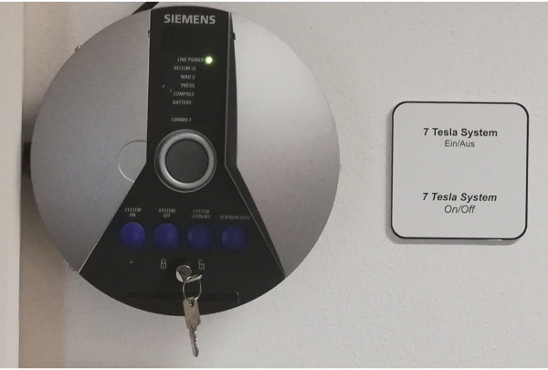
Figure 1. Switch box of Siemens MR scanner Please click here to view a larger version of this figure.
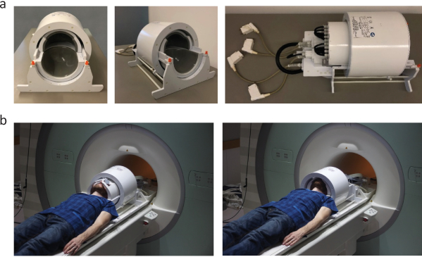
Figure 2. Connecting a dedicated RF coil to the MR system. (a) Transmit (Tx), 24- or 32 channel receive (Rx) radio frequency head coil tailored for brain MRI at 7.0 T (b) Instruct the subject to move closer to the RF head coil and position the head of the subject over the lower RX-coil and beneath the upper RX-coil (left panel). Next move the TX-part of the RF head coil over the RX-coil (bottom right). Please click here to view a larger version of this figure.
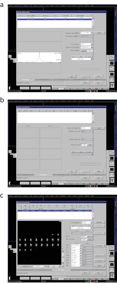
Figure 3. Running adjustments (Siemens system). (a) Basic frequency adjustment, (b) Transmitter voltage adjustment, (c) Generation of B0 Map and 3D shimming. Please click here to view a larger version of this figure.
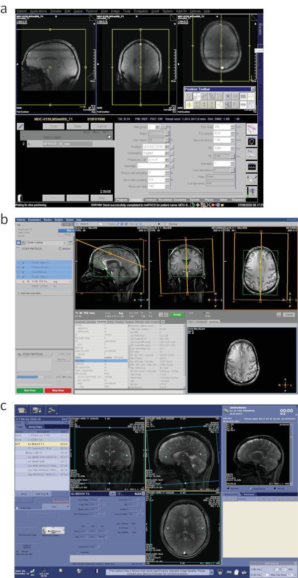
Figure 4. MR sequence planning on 7.0 T MR systems from different vendors. (a) Siemens, (b) Philips and (c) General Electric. Please click here to view a larger version of this figure.
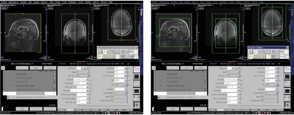
Figure 5. Planning 3D MP2RAGE imaging sequence Please click here to view a larger version of this figure.
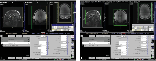
Figure 6. Planning 3D SPACE-FLAIR imaging sequence Please click here to view a larger version of this figure.
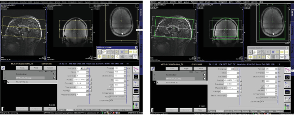
Figure 7. Planning 2D FLASH-ME imaging sequence Please click here to view a larger version of this figure.
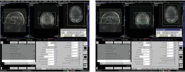
Figure 8. Planning 3D susceptibility weighted imaging sequence Please click here to view a larger version of this figure.
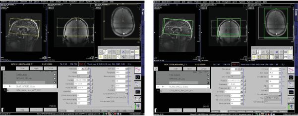
Figure 9. Planning QSM-FC Please click here to view a larger version of this figure.
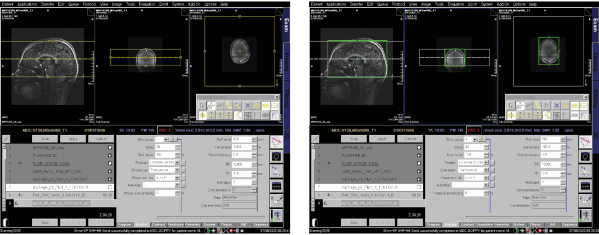
Figure 10. Planning diffusion-weighted echo-planar imaging sequence Please click here to view a larger version of this figure.
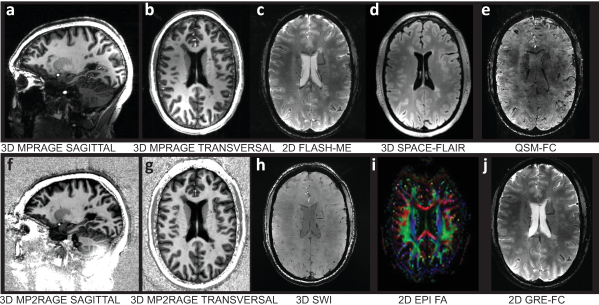
Figure 11. Representative results of high-resolution brain MRI of an RRMS patient Upper panel from left to right: (a) sagittal view of a T1w 3D inversion recovery-prepared spoiled-GRE sequence (MPRAGE), (b) transversal view of T1w 3D MPRAGE, (c) transversal view of T2*w 2D FLASH sequence with multi-echo readout (FLASH-ME), (d) transversal view of a T2w fluid-attenuated inversion recovery using sampling perfection with application-optimized contrasts using different flip angle evolutions (SPACE-FLAIR), (e) transversal view of flow compensated quantitative susceptibility mapping (QSM-FC). Lower panel from left to right: (f) sagittal view of a T1w 3D magnetization-prepared rapid gradient echo sequence (MP2RAGE), (g) transversal view of T1w 3D MP2RAGE, (h) transversal view of 3D susceptibility weighted imaging (SWI) using magnitude and phase data of a fully flow-compensated GE sequence, (i) combined fractional anisotropy map and directional map of an echo-planar diffusion-weighted imaging sequence (2D EPI), (j) transversal view of T2*w 2D gradient echo imaging with flow compensation (GRE-FC). Please click here to view a larger version of this figure.
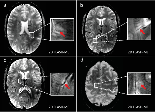
Figure 12. Representative white-matter MS lesions with central vein sign (a and b) Transversal view of T2*w 2D FLASH sequence with multi-echo readout (FLASH-ME) reveals highly MS-specific central vein sign (red arrow) within exemplary periventricular lesions, (c) a right-hemispheric thalamic lesion (d), and a parietal juxtacortical lesion, substantiating the patient's MS diagnosis. Please click here to view a larger version of this figure.
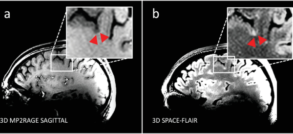
Figure 13. Representative cortical MS lesion. (a) Sagittal view of a T1w 3D magnetization-prepared rapid gradient echo sequence (MP2RAGE) delineates subpial cortical lesion (red arrow heads) within parietal cortex (b) with corresponding hyperintensity in transversal view of a T2w fluid-attenuated inversion recovery (SPACE-FLAIR), indicating the occurrence of cortical MS pathology in the relapsing-remitting MS patient. Please click here to view a larger version of this figure.
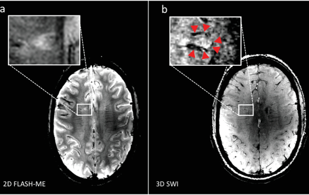
Figure 14. Representative hypointense rim structures. (a) Transversal view of T2*w 2D FLASH sequence with multi-echo readout (FLASH-ME) reveals an ovoid periventricular MS lesion, and (b) transversal view of 3D susceptibility weighted imaging (SWI) delineates a hypointense rim structure around the lesion, suggesting iron-laden macrophages to be present as a potential surrogate for MS lesion activity. Please click here to view a larger version of this figure.
| Metallic implants (can malfunction due to magnetic fields or cause injury) |
| Electronic devices e.g. pacemakers, defibrillators, insulin pump, nerve stimulators |
| Aneurysm and haemostatic clips, prosthetic heart valves |
| Cochlear, otologic implants |
| Drug infusion devices |
| Deep brain stimulation electrodes |
| Lead electrocardiogram wires |
| Other contraindications (risk of skin burns, swelling or damage via magnetic field effects) |
| Some medication patches |
| Metallic foreign bodies e.g. shrapnel or other minute metal fragments in the eye |
| Some tattoo and cosmetics (permanent makeup) |
| Body piercing jewellery |
| Pregnancy (possible adverse biological effects by magnetic fields) |
| Known claustrophobia |
Table 1. Principal contraindications of an MRI examination. The most common contraindications are metallic implants. Implants are becoming increasingly MR safe (MRI-conditional) but remain a major concern.
Discussion
The protocol presented here describes a series of MRI sequences with different contrasts that are typically used when examining MS patients at 7.0 T. Together with emerging technological developments, they provide the basis for explorations into more advanced applications in metabolic or functional imaging.
Aside from brain lesions, lesions in the spinal cord frequently affect MS patients causing motor, sensory and autonomic dysfunction. However spinal cord imaging, particularly at 7.0 T, is technically challenging113. Further developments in parallel transmission and parallel imaging are warranted to overcome the hurdles of distorted B1 field profiles114.
The goal of this protocol is to disseminate and synergistically connect technology developments and clinical application across disciplinary domains. Aside from the expected enhancements in spatial and temporal resolution, opportunities from the changing physical characteristics of higher magnetic fields include better contrasts in susceptibility-weighted imaging (SWI) and phase-contrast techniques115, as well as imaging of X-nuclei such as sodium116,117 and fluorine118,119,120 for a more in depth assessment of the pathology as well as therapeutic monitoring.
Disclosures
The authors have nothing to disclose.
Acknowledgements
This project (T.N.) has received funding in part from the European Research Council (ERC) under the European Union's Horizon 2020 research and innovation program under grant agreement No 743077 (ThermalMR). The authors wish to thank the teams at the Berlin Ultrahigh Field Facility (B.U.F.F.), Max Delbrueck Center for Molecular Medicine in the Helmholtz Association, Berlin, Germany; at the The Swedish National 7T Facility, Lund University Bioimaging Center, Lund University, Lund, Sweden and at the ECOTECH-COMPLEX, Maria Curie-Skłodowska University, Lublin, Poland for technical and other assistance.
Materials
| 7T TX/RX 24 Ch Head Coil | Nova Medical, Inc., Wilmington, USA | NM008-24-7S-013 | 1-channel circular polarized (CP) transmit (Tx), 24-channel receive (Rx) RF head coil |
| Magnetom 7T System | Siemens Healthineers, Erlangen, Germany | MRB1076 | 7.0 T whole body research scanner |
| syngoMR B17 Software | Siemens Healthineers, Erlangen, Germany | B17A | image processing software for the Magnetom 7T system |
References
- Filippi, M., et al. Multiple sclerosis. Nature Reviews Disease Primers. 4 (1), 43 (2018).
- Krieger, S. C., Cook, K., De Nino, S., Fletcher, M. The topographical model of multiple sclerosis: A dynamic visualization of disease course. Neurology: Neuroimmunology & Neuroinflammation. 3 (5), 279 (2016).
- Kutzelnigg, A., et al. Cortical demyelination and diffuse white matter injury in multiple sclerosis. Brain. 128 (11), 2705-2712 (2005).
- Kuchling, J., Paul, F. Visualizing the Central Nervous System: Imaging Tools for Multiple Sclerosis and Neuromyelitis Optica Spectrum Disorders. Frontiers in Neurology. 11, 450 (2020).
- Lassmann, H. Multiple Sclerosis Pathology. Cold Spring Harbor Perspectives in Medicine. 8 (3), (2018).
- Miller, D. H., Chard, D. T., Ciccarelli, O. Clinically isolated syndromes. The Lancet Neurology. 11 (2), 157-169 (2012).
- van der Vuurst de Vries, R. M., et al. Application of the 2017 Revised McDonald Criteria for Multiple Sclerosis to Patients With a Typical Clinically Isolated Syndrome. JAMA Neurologyogy. 75 (11), 1392-1398 (2018).
- Thompson, A. J., et al. Diagnosis of multiple sclerosis: 2017 revisions of the McDonald criteria. The Lancet Neurology. 17 (2), 162-173 (2018).
- Filippi, M., Preziosa, P., Rocca, M. A. Multiple sclerosis. Handbook of Clinical Neurology. 135, 399-423 (2016).
- Rovira, A., de Stefano, N. MRI monitoring of spinal cord changes in patients with multiple sclerosis. Current Opinion in Neurology. 29 (4), 445-452 (2016).
- Filippi, M., et al. Assessment of lesions on magnetic resonance imaging in multiple sclerosis: practical guidelines. Brain. , (2019).
- Kuhle, J., et al. Conversion from clinically isolated syndrome to multiple sclerosis: a large multicentre study. Multiple Sclerosis Journal. 21 (8), 1013-1024 (2015).
- El-Khatib, A. H., et al. Gadolinium in human brain sections and colocalization with other elements. Neurology: Neuroimmunology & Neuroinflammation. 6 (1), 515 (2019).
- McDonald, R. J., et al. Intracranial Gadolinium Deposition after Contrast-enhanced MR Imaging. Radiology. 275 (3), 772-782 (2015).
- McDonald, R. J., et al. Gadolinium Deposition in Human Brain Tissues after Contrast-enhanced MR Imaging in Adult Patients without Intracranial Abnormalities. Radiology. 285 (2), 546-554 (2017).
- Schlemm, L., et al. Gadopentetate but not gadobutrol accumulates in the dentate nucleus of multiple sclerosis patients. Multiple Sclerosis. 23 (7), 963-972 (2017).
- Boyken, J., Niendorf, T., Flemming, B., Seeliger, E. Gadolinium Deposition in the Brain after Contrast-enhanced MRI: Are the Data Valid. Radiology. 288 (2), 630-632 (2018).
- Rovira, &. #. 1. 9. 2. ;. a. l., et al. MAGNIMS consensus guidelines on the use of MRI in multiple sclerosis-clinical implementation in the diagnostic process. Nature Reviews Neurology. 11, 471 (2015).
- Wattjes, M. P., et al. MAGNIMS consensus guidelines on the use of MRI in multiple sclerosis-establishing disease prognosis and monitoring patients. Nature Reviews Neurology. 11 (10), 597-606 (2015).
- Traboulsee, A., et al. Revised Recommendations of the Consortium of MS Centers Task Force for a Standardized MRI Protocol and Clinical Guidelines for the Diagnosis and Follow-Up of Multiple Sclerosis. American Journal of Neuroradiology. 37 (3), 394-401 (2016).
- Sąsiadek, M., et al. Recommendations of the Polish Medical Society of Radiology and the Polish Society of Neurology for the routinely used magnetic resonance imaging protocol in patients with multiple sclerosis. Polish Journal of Radiology. 85, 272-276 (2020).
- Maranzano, J., et al. Comparison of multiple sclerosis cortical lesion types detected by multicontrast 3T and 7T MRI. American Journal of Neuroradiology. 40 (7), 1162-1169 (2019).
- Arevalo, O., Riascos, R., Rabiei, P., Kamali, A., Nelson, F. Standardizing Magnetic Resonance Imaging Protocols, Requisitions, and Reports in Multiple Sclerosis: An Update for Radiologist Based on 2017 Magnetic Resonance Imaging in Multiple Sclerosis and 2018 Consortium of Multiple Sclerosis Centers Consensus Guidelines. Journal of Computer Assisted Tomography. 43 (1), 1-12 (2019).
- Schmierer, K., et al. Towards a standard MRI protocol for multiple sclerosis across the UK. The British Journal of Radiology. 92 (1101), 20180926 (2019).
- Pereira, D. J., et al. Consensus Recommendations of the Multiple Sclerosis Study Group and the Portuguese Neuroradiological Society for the Use of Magnetic Resonance Imaging in Multiple Sclerosis in Clinical Practice: Part 2. Acta Médica Portuguesa. 33 (1), 66-75 (2020).
- Zivadinov, R., Bakshi, R. Role of MRI in multiple sclerosis I: inflammation and lesions. Front Biosci. 9 (665), 28 (2004).
- Hemond, C. C., Bakshi, R. Magnetic resonance imaging in multiple sclerosis. Cold Spring Harbor Perspectives in Medicine. 8 (5), 028969 (2018).
- Thompson, A. J., et al. Diagnosis of multiple sclerosis: 2017 revisions of the McDonald criteria. The Lancet Neurology. 17 (2), 162-173 (2018).
- Neema, M., et al. T1-and T2-based MRI measures of diffuse gray matter and white matter damage in patients with multiple sclerosis. Journal of Neuroimaging. 17, 16-21 (2007).
- Shepherd, T. M., et al. New rapid, accurate T(2) quantification detects pathology in normal-appearing brain regions of relapsing-remitting MS patients. NeuroImage. Clinical. 14 (2), 363-370 (2017).
- Tallantyre, E. C., et al. A comparison of 3T and 7T in the detection of small parenchymal veins within MS lesions. Investigative Radiology. 44 (9), 491-494 (2009).
- Geraldes, R., et al. The current role of MRI in differentiating multiple sclerosis from its imaging mimics. Nature Reviews Neurology. 14 (4), 199 (2018).
- Sinnecker, T., et al. Evaluation of the Central Vein Sign as a Diagnostic Imaging Biomarker in Multiple Sclerosis. JAMA Neurology. 76 (12), 1446-1456 (2019).
- Bagnato, F., et al. Untangling the R2* contrast in multiple sclerosis: a combined MRI-histology study at 7.0 Tesla. Public Library of Science one. 13 (3), (2018).
- Walsh, A. J., et al. Multiple sclerosis: validation of MR imaging for quantification and detection of iron. Radiology. 267 (2), 531-542 (2013).
- Bozin, I., et al. Magnetic resonance phase alterations in multiple sclerosis patients with short and long disease duration. Public Library of Science one. 10 (7), 0128386 (2015).
- Ropele, S., et al. Determinants of iron accumulation in deep grey matter of multiple sclerosis patients. Multiple Sclerosis Journal. 20 (13), 1692-1698 (2014).
- Walsh, A. J., et al. Longitudinal MR imaging of iron in multiple sclerosis: an imaging marker of disease. Radiology. 270 (1), 186-196 (2014).
- Blazejewska, A. I., et al. Increase in the iron content of the substantia nigra and red nucleus in multiple sclerosis and clinically isolated syndrome: a 7 Tesla MRI study. Journal of Magnetic Resonance Imaging. 41 (4), 1065-1070 (2015).
- Bonnier, G., et al. Advanced MRI unravels the nature of tissue alterations in early multiple sclerosis. Annals of Clinical and Translational Neurology. 1 (6), 423-432 (2014).
- Niendorf, T., Barth, M., Kober, F., Trattnig, S. From ultrahigh to extreme field magnetic resonance: where physics, biology and medicine meet. MAGMA. 29 (3), 309-311 (2016).
- Sinnecker, T., et al. Ultrahigh field MRI in clinical neuroimmunology: a potential contribution to improved diagnostics and personalised disease management. EPMA. 6 (1), 16 (2015).
- Vaughan, J. T., et al. 7T vs. 4T: RF power, homogeneity, and signal-to-noise comparison in head images. Magnetic Resonance in Medicine. 46 (1), 24-30 (2001).
- Padormo, F., Beqiri, A., Hajnal, J. V., Malik, S. J. Parallel transmission for ultrahigh-field imaging. NMR in Biomedicine. 29 (9), 1145-1161 (2016).
- Bruschi, N., Boffa, G., Inglese, M. Ultra-high-field 7-T MRI in multiple sclerosis and other demyelinating diseases: from pathology to clinical practice. European Radiology Experimental. 4 (1), 59 (2020).
- Sati, P., et al. The central vein sign and its clinical evaluation for the diagnosis of multiple sclerosis: a consensus statement from the North American Imaging in Multiple Sclerosis Cooperative. Nature Reviews Neurology. 12 (12), 714-722 (2016).
- Tan, I. L., et al. MR venography of multiple sclerosis. American Journal of Neuroradiology. 21 (6), 1039-1042 (2000).
- Maggi, P., et al. The formation of inflammatory demyelinated lesions in cerebral white matter. Annals of Neurology. 76 (4), 594-608 (2014).
- Tallantyre, E. C., et al. A comparison of 3T and 7T in the detection of small parenchymal veins within MS lesions. Investigative Radiology. 44 (9), 491-494 (2009).
- Filippi, M., et al. Assessment of lesions on magnetic resonance imaging in multiple sclerosis: practical guidelines. Brain. 142 (7), 1858-1875 (2019).
- Muller, K., et al. Detailing intra-lesional venous lumen shrinking in multiple sclerosis investigated by sFLAIR MRI at 7-T. Journal of Neurology. , (2014).
- Sinnecker, T., et al. Periventricular venous density in multiple sclerosis is inversely associated with T2 lesion count: a 7 Tesla MRI study. Multiple Sclerosis. 19 (3), 316-325 (2013).
- Wuerfel, J., et al. Lesion morphology at 7 Tesla MRI differentiates Susac syndrome from multiple sclerosis. Multiple Sclerosis. 18 (11), 1592-1599 (2012).
- Sinnecker, T., et al. Distinct lesion morphology at 7-T MRI differentiates neuromyelitis optica from multiple sclerosis. Neurology. 79 (7), 708-714 (2012).
- Kuchling, J., et al. Identical lesion morphology in primary progressive and relapsing-remitting MS–an ultrahigh field MRI study. Multiple Sclerosis. 20 (14), 1866-1871 (2014).
- Sinnecker, T., et al. Multiple sclerosis lesions and irreversible brain tissue damage: a comparative ultrahigh-field strength magnetic resonance imaging study. Archives of Neurology. 69 (6), 739-745 (2012).
- Behrens, J. R., et al. 7 Tesla MRI of Balo’s concentric sclerosis versus multiple sclerosis lesions. Annals of Clinical and Translational Neurology. 5 (8), 900-912 (2018).
- Blaabjerg, M., et al. Widespread inflammation in CLIPPERS syndrome indicated by autopsy and ultra-high-field 7T MRI. Neurology: Neuroimmunology & Neuroinflammation. 3 (3), 226 (2016).
- Noureddine, Y., et al. Experience with magnetic resonance imaging of human subjects with passive implants and tattoos at 7 T: a retrospective study. Magnetic Resonance Materials in Physics, Biology and Medicine. 28 (6), 577-590 (2015).
- Kraff, O., Quick, H. H. 7T: Physics, safety, and potential clinical applications. Journal of Magnetic Resonance Imaging. 46 (6), 1573-1589 (2017).
- Hoff, M. N., et al. Safety Considerations of 7-T MRI in Clinical Practice. Radiology. 292 (3), 509-518 (2019).
- Kraff, O., Quick, H. H. Sicherheit von Implantaten im Hochfeld- und Ultrahochfeld-MRT. Der Radiologe. 59 (10), 898-905 (2019).
- Fagan, A. J., et al. 7T MR Safety. Journal of Magnetic Resonance Imaging. , (2020).
- . MR Safety Guidance, Documents and Links: MR Safety Strategies to Help You Stay Current with MR Safety Standards Available from: https://www.ismrm.org/mr-safety-links/mr-safety-resources-page/ (2020)
- Versluis, M. J., et al. Subject tolerance of 7 T MRI examinations. Journal of Magnetic Resonance Imaging. 38 (3), 722-725 (2013).
- Theysohn, J. M., et al. Subjective acceptance of 7 Tesla MRI for human imaging. Magnetic Resonance Materials in Physics, Biology and Medicine. 21 (1-2), 63 (2008).
- Klix, S., et al. On the Subjective Acceptance during Cardiovascular Magnetic Resonance Imaging at 7.0 Tesla. PLoS One. 10 (1), 0117095 (2015).
- Rauschenberg, J., et al. Multicenter study of subjective acceptance during magnetic resonance imaging at 7 and 9.4 T. Investigative Radiology. 49 (5), 249-259 (2014).
- Zurawski, J., Lassmann, H., Bakshi, R. Use of Magnetic Resonance Imaging to Visualize Leptomeningeal Inflammation in Patients With Multiple Sclerosis: A Review. JAMA Neurologyogy. 74 (1), 100-109 (2017).
- Radue, E. -. W., et al. Correlation between brain volume loss and clinical and MRI outcomes in multiple sclerosis. Neurology. 84 (8), 784-793 (2015).
- Filippi, M., et al. A high-resolution three-dimensional T1-weighted gradient echo sequence improves the detection of disease activity in multiple sclerosis. Annals of Neurology. 40 (6), 901-907 (1996).
- Mugler, J. P., Brookeman, J. R. Three-dimensional magnetization-prepared rapid gradient-echo imaging (3D MP RAGE). Magnetic Resonance in Medicine. 15 (1), 152-157 (1990).
- Lindig, T., et al. Evaluation of multimodal segmentation based on 3D T1-, T2- and FLAIR-weighted images – the difficulty of choosing. NeuroImage. 170, 210-221 (2018).
- Nelson, F., Poonawalla, A., Hou, P., Wolinsky, J. S., Narayana, P. A. 3D MPRAGE improves classification of cortical lesions in multiple sclerosis. Multiple sclerosis. 14 (9), 1214-1219 (2008).
- Marques, J. P., et al. MP2RAGE, a self bias-field corrected sequence for improved segmentation and T1-mapping at high field. NeuroImage. 49 (2), 1271-1281 (2010).
- Kober, T., et al. MP2RAGE Multiple Sclerosis Magnetic Resonance Imaging at 3 T. Investigative Radiology. 47 (6), 346-352 (2012).
- Beck, E. S., et al. Improved Visualization of Cortical Lesions in Multiple Sclerosis Using 7T MP2RAGE. American Journal of Neuroradiology. 39 (3), 459-466 (2018).
- Bø, L., Vedeler, C. A., Nyland, H. I., Trapp, B. D., Mørk, S. J. Subpial Demyelination in the Cerebral Cortex of Multiple Sclerosis Patients. Journal of Neuropathology, Experimental Neurology. 62 (7), 723-732 (2003).
- Kilsdonk, I. D., et al. Increased cortical grey matter lesion detection in multiple sclerosis with 7 T MRI: a post-mortem verification study. Brain. 139 (5), 1472-1481 (2016).
- Absinta, M., et al. Gadolinium-based MRI characterization of leptomeningeal inflammation in multiple sclerosis. Neurology. 85 (1), 18-28 (2015).
- Titelbaum, D. S., et al. Leptomeningeal Enhancement on 3D-FLAIR MRI in Multiple Sclerosis: Systematic Observations in Clinical Practice. Journal of Neuroimaging. 30 (6), 917-929 (2020).
- Schmidt, P., et al. Automated segmentation of changes in FLAIR-hyperintense white matter lesions in multiple sclerosis on serial magnetic resonance imaging. NeuroImage: Clinical. 23, 101849 (2019).
- Coulette, S., et al. Diagnosis and Prediction of Relapses in Susac Syndrome: A New Use for MR Postcontrast FLAIR Leptomeningeal Enhancement. American Journal of Neuroradiology. 40 (7), 1184-1190 (2019).
- Cohen-Adad, J., et al. T2* mapping and B0 orientation-dependence at 7T reveal cyto- and myeloarchitecture organization of the human cortex. NeuroImage. 60 (2), 1006-1014 (2012).
- Louapre, C., et al. The association between intra- and juxta-cortical pathology and cognitive impairment in multiple sclerosis by quantitative T2* mapping at 7T MRI. NeuroImage: Clinical. 12, 879-886 (2016).
- Liu, S., et al. Susceptibility-weighted imaging: current status and future directions. NMR in Biomedicine. 30 (4), 3552 (2017).
- Haacke, E. M., Xu, Y., Cheng, Y. C., Reichenbach, J. R. Susceptibility weighted imaging (SWI). Magnetic Resonance in Medicine. 52 (3), 612-618 (2004).
- Haacke, E. M., et al. Characterizing iron deposition in multiple sclerosis lesions using susceptibility weighted imaging. Journal of Magnetic Resonance Imaging. 29 (3), 537-544 (2009).
- Pitt, D., et al. Imaging Cortical Lesions in Multiple Sclerosis With Ultra-High-Field Magnetic Resonance Imaging. Archives of Neurology. 67 (7), 812-818 (2010).
- Li, X., et al. Magnetic susceptibility contrast variations in multiple sclerosis lesions. Journal of Magnetic Resonance Imaging. 43 (2), 463-473 (2016).
- Dal-Bianco, A., et al. Slow expansion of multiple sclerosis iron rim lesions: pathology and 7 T magnetic resonance imaging. Acta Neuropathologica. 133 (1), 25-42 (2017).
- Sati, P. Diagnosis of multiple sclerosis through the lens of ultra-high-field MRI. Journal of Magnetic Resonance. 291, 101-109 (2018).
- Griswold, M. A., et al. Generalized autocalibrating partially parallel acquisitions (GRAPPA). Magnetic Resonance in Medicine. 47 (6), 1202-1210 (2002).
- Hammond, K. E., et al. Development of a robust method for generating 7.0 T multichannel phase images of the brain with application to normal volunteers and patients with neurological diseases. NeuroImage. 39 (4), 1682-1692 (2008).
- Haacke, E. M., et al. Quantitative susceptibility mapping: current status and future directions. Magnetic Resonance Imaging. 33 (1), 1-25 (2015).
- Langkammer, C., et al. Quantitative susceptibility mapping in multiple sclerosis. Radiology. 267 (2), 551-559 (2013).
- Eskreis-Winkler, S., et al. Multiple sclerosis lesion geometry in quantitative susceptibility mapping (QSM) and phase imaging. Journal of Magnetic Resonance Imaging. 42 (1), 224-229 (2015).
- Chawla, S., et al. Longitudinal study of multiple sclerosis lesions using ultra-high field (7T) multiparametric MR imaging. PLOS ONE. 13 (9), 0202918 (2018).
- Kolasinski, J., et al. A combined post-mortem magnetic resonance imaging and quantitative histological study of multiple sclerosis pathology. Brain. 135 (10), 2938-2951 (2012).
- De Santis, S., et al. Evidence of early microstructural white matter abnormalities in multiple sclerosis from multi-shell diffusion MRI. NeuroImage: Clinical. 22, 101699 (2019).
- Filippi, M., et al. Microstructural magnetic resonance imaging of cortical lesions in multiple sclerosis. Multiple Sclerosis. 19 (4), 418-426 (2013).
- Granberg, T., et al. In vivo characterization of cortical and white matter neuroaxonal pathology in early multiple sclerosis. Brain: a Journal of Neurology. 140 (11), 2912-2926 (2017).
- Holland, D., Kuperman, J. M., Dale, A. M. Efficient correction of inhomogeneous static magnetic field-induced distortion in Echo Planar Imaging. NeuroImage. 50 (1), 175-183 (2010).
- In, M. -. H., Posnansky, O., Beall, E. B., Lowe, M. J., Speck, O. Distortion correction in EPI using an extended PSF method with a reversed phase gradient approach. PloS one. 10 (2), 0116320 (2015).
- Van de Moortele, P. F., et al. B(1) destructive interferences and spatial phase patterns at 7 T with a head transceiver array coil. Magnetic Resonance in Medicine. 54 (6), 1503-1518 (2005).
- Collins, C. M., Liu, W., Schreiber, W., Yang, Q. X., Smith, M. B. Central brightening due to constructive interference with, without, and despite dielectric resonance. Journal of Magnetic Resonance Imaging. 21 (2), 192-196 (2005).
- Yang, Q. X., et al. Manipulation of image intensity distribution at 7.0 T: passive RF shimming and focusing with dielectric materials. Journal of Magnetic Resonance Imaging. 24 (1), 197-202 (2006).
- Teeuwisse, W. M., Brink, W. M., Webb, A. G. Quantitative assessment of the effects of high-permittivity pads in 7 Tesla MRI of the brain. Magnetic Resonance in Medicine. 67 (5), 1285-1293 (2012).
- van Gemert, J., Brink, W., Webb, A., Remis, R. High-permittivity pad design tool for 7T neuroimaging and 3T body imaging. Magnetic Resonance in Medicine. 81 (5), 3370-3378 (2019).
- Vaidya, M. V., et al. Improved detection of fMRI activation in the cerebellum at 7T with dielectric pads extending the imaging region of a commercial head coil. Journal of Magnetic Resonance Imaging. 48 (2), 431-440 (2018).
- Brink, W. M., vander Jagt, A. M., Versluis, M. J., Verbist, B. M., Webb, A. G. High permittivity dielectric pads improve high spatial resolution magnetic resonance imaging of the inner ear at 7 T. Investigative Radiology. 49 (5), 271-277 (2014).
- Lundkvist, M., et al. Characterization of anti-natalizumab antibodies in multiple sclerosis patients. Multiple Sclerosis. 19 (6), 757-764 (2013).
- Moccia, M., et al. Advances in spinal cord imaging in multiple sclerosis. Therapeutic Advances in Neurological Disorders. 12, 1756286419840593 (2019).
- Zhao, W., et al. Nineteen-channel receive array and four-channel transmit array coil for cervical spinal cord imaging at 7T. Magnetic Resonance in Medicine. 72 (1), 291-300 (2014).
- Sinnecker, T., et al. MRI phase changes in multiple sclerosis vs neuromyelitis optica lesions at 7T. Neurology: Neuroimmunology & Neuroinflammation. 3 (4), 259 (2016).
- Wenz, D., et al. Millimeter spatial resolution in vivo sodium MRI of the human eye at 7 T using a dedicated radiofrequency transceiver array. Magnetic Resonance in Medicine. 80 (2), 672-684 (2018).
- Huhn, K., Engelhorn, T., Linker, R. A., Nagel, A. M. Potential of Sodium MRI as a Biomarker for Neurodegeneration and Neuroinflammation in Multiple Sclerosis. Frontiers in Neurology. 10 (84), (2019).
- Bolo, N. R., et al. Brain Pharmacokinetics and Tissue Distribution In Vivo of Fluvoxamine and Fluoxetine by Fluorine Magnetic Resonance Spectroscopy. Neuropsychopharmacology. 23 (4), 428-438 (2000).
- Ji, Y., et al. Eight-channel transceiver RF coil array tailored for 1H/19F MR of the human knee and fluorinated drugs at 7.0 T. NMR in Biomedicine. 28 (6), 726-737 (2015).
- Starke, L., Pohlmann, A., Prinz, C., Niendorf, T., Waiczies, S. Performance of compressed sensing for fluorine-19 magnetic resonance imaging at low signal-to-noise ratio conditions. Magnetic Resonance in Medicine. , 1-17 (2019).
