Summary

Atomic Force Microscopy Cantilever-Based Nanoindentation: Mekaniske egenskabsmålinger på nanoskala i luft og væske

Published: December 02, 2022
doi:

Summary

Kvantificering af kontaktområdet og kraften, der påføres af et atomkraftmikroskop (AFM) sondespids på en prøveoverflade, muliggør bestemmelse af mekaniske egenskaber i nanoskala. Bedste praksis for implementering af AFM-udkragningsbaseret nanoindrykning i luft eller væske på bløde og hårde prøver til måling af elastisk modul eller andre nanomekaniske egenskaber diskuteres.

Abstract

Et atomkraftmikroskop (AFM) måler fundamentalt interaktionen mellem en nanoskala AFM-sondespids og prøveoverfladen. Hvis den kraft, der påføres af sondespidsen og dens kontaktområde med prøven, kan kvantificeres, er det muligt at bestemme nanoskalaens mekaniske egenskaber (f.eks. elastik eller Youngs modul) af overfladen, der undersøges. En detaljeret procedure til udførelse af kvantitative AFM cantilever-baserede nanoindrykningseksperimenter gives her med repræsentative eksempler på, hvordan teknikken kan anvendes til at bestemme de elastiske moduli af en lang række prøvetyper, lige fra kPa til GPa. Disse omfatter levende mesenkymale stamceller (MSC’er) og kerner i fysiologisk buffer, harpiksindlejrede dehydrerede loblolly fyrretræstværsnit og Bakken-skifer af varierende sammensætning.

Derudover anvendes AFM-udkragningsbaseret nanoindrykning til at undersøge brudstyrken (dvs. gennembrudskraften) af phospholipid-dobbeltlag. Vigtige praktiske overvejelser såsom metodevalg og udvikling, sondevalg og kalibrering, identifikation af interesseområde, prøveheterogenitet, funktionsstørrelse og billedformat, spidsslid, overfladeruhed og dataanalyse og målestatistikker diskuteres for at hjælpe med korrekt implementering af teknikken. Endelig demonstreres samlokalisering af AFM-afledte nanomekaniske kort med elektronmikroskopiteknikker, der giver yderligere information om elementær sammensætning.

Introduction

Forståelse af materialers mekaniske egenskaber er en af de mest grundlæggende og væsentlige opgaver inden for teknik. Til analyse af bulkmaterialeegenskaber er der adskillige metoder til rådighed til at karakterisere de mekaniske egenskaber ved materialesystemer, herunder træktest1, kompressionstest2 og tre- eller firepunkts bøjningstest (bøjning)3. Mens disse mikroskalatest kan give uvurderlig information om bulkmaterialeegenskaber, udføres de generelt til fiasko og er derfor destruktive. Derudover mangler de den rumlige opløsning, der er nødvendig for nøjagtigt at undersøge mikro- og nanoskalaegenskaberne for mange materialesystemer, der er af interesse i dag, såsom tyndfilm, biologiske materialer og nanokompositter. For at begynde at løse nogle af problemerne med storskala mekanisk testning, hovedsageligt dens destruktive karakter, blev mikrohårdhedstest vedtaget fra mineralogi. Hårdhed er et mål for et materiales modstand mod plastisk deformation under specifikke forhold. Generelt bruger mikrohardhedstest en stiv sonde, normalt lavet af hærdet stål eller diamant, til at indrykke i et materiale. Den resulterende indrykningsdybde og / eller areal kan derefter bruges til at bestemme hårdheden. Flere metoder er blevet udviklet, herunder Vickers4, Knoop5 og Brinell6 hårdhed; Hver giver et mål for mikroskala materialehårdhed, men under forskellige betingelser og definitioner, og producerer som sådan kun data, der kan sammenlignes med test udført under de samme betingelser.

Instrumenteret nanoindrykning blev udviklet for at forbedre de relative værdier opnået via de forskellige mikrohårdhedstestmetoder, forbedre den rumlige opløsning, der er mulig til analyse af mekaniske egenskaber, og muliggøre analyse af tynde film. Det er vigtigt, at ved at bruge metoden, der først blev udviklet af Oliver og Pharr7, kan elastikken eller Youngs modul, E, af et prøvemateriale bestemmes via instrumenteret nanoindrykning. Ved at anvende en Berkovich tresidet pyramideformet nanoindentersonde (hvis ideelle spidsområdefunktion matcher Vickers firesidede pyramidesonde)8, kan der desuden foretages direkte sammenligning mellem nanoskala og mere traditionelle mikroskala hårdhedsmålinger. Med AFM’s voksende popularitet begyndte AFM-udkragningsbaseret nanoindrykning også at få opmærksomhed, især til måling af blødere materialers mekaniske egenskaber. Som et resultat, som vist skematisk i figur 1, er de to mest almindeligt anvendte teknikker i dag til at forhøre og kvantificere mekaniske egenskaber i nanoskala instrumenteret nanoindrykning (figur 1A) og AFM-udkragningsbaseret nanoindrykning (figur 1B)9, hvoraf sidstnævnte er fokus for dette arbejde.

Figure 1
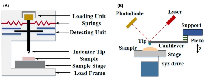
Figur 1: Sammenligning af instrumenterede og AFM-udkragningsbaserede nanoindrykningssystemer. Skematiske diagrammer, der viser typiske systemer til udførelse af (A) instrumenteret nanoindrykning og (B) AFM-udkragningsbaseret nanoindrykning. Dette tal blev ændret fra Qian et al.51. Forkortelse: AFM = atomkraftmikroskopi. Klik her for at se en større version af denne figur.

Både instrumenteret og AFM-udkragningsbaseret nanoindrykning anvender en stiv sonde til at deformere en prøveoverflade af interesse og overvåge den resulterende kraft og forskydning som en funktion af tiden. Typisk specificeres enten den ønskede belastnings- (dvs. kraft) eller (Z-piezo) forskydningsprofil af brugeren via softwaregrænsefladen og styres direkte af instrumentet, mens den anden parameter måles. Den mekaniske egenskab, der oftest opnås ved nanoindrykningseksperimenter, er det elastiske modul (E), også kaldet Youngs modul, som har trykenheder. Et materiales elastiske modul er en grundlæggende egenskab i forbindelse med bindingsstivheden og defineres som forholdet mellem træk- eller trykspænding (σ, den påførte kraft pr. arealenhed) og aksial belastning (ε, den proportionale deformation langs indrykningsaksen) under elastisk (dvs. reversibel eller midlertidig) deformation før plastisk deformation (ligning [1]):

Equation 1(1)

Det skal bemærkes, at fordi mange materialer (især biologiske væv) faktisk er viskoelastiske, består det (dynamiske eller komplekse) modul i virkeligheden af både elastiske (opbevaring, i fase) og viskøse (tab, ud af fase) komponenter. I praksis er det, der måles i et nanoindrykningseksperiment, det reducerede modul, E *, som er relateret til det sande prøvemodul af interesse, E, som vist i ligning (2):
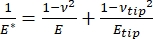
Equation 2(2)

Hvor E-spids og ν-spids er henholdsvis det elastiske modul og Poissons forhold mellem nanoindenterspidsen, og ν er det estimerede Poissons forhold mellem prøven. Poissons forhold er det negative forhold mellem den tværgående og aksiale stamme og angiver derfor graden af tværgående forlængelse af en prøve, når den udsættes for aksial belastning (f.eks. under nanoindrykningsbelastning), som vist i ligning (3):
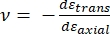
Equation 3(3)

Omdannelsen fra reduceret til faktisk modul er nødvendig, fordi a) noget af den aksiale belastning, der tilføres af indenterspidsen, kan omdannes til tværgående belastning (dvs. prøven kan deformeres via ekspansion eller sammentrækning vinkelret på belastningsretningen), og b) indenterspidsen ikke er uendelig hård, og således resulterer handlingen med at indrykke prøven i en vis (lille) deformation af spidsen. Bemærk, at i det tilfælde, hvor E-spidsen >> E (dvs. indenterspidsen er meget hårdere end prøven, hvilket ofte er sandt, når man bruger en diamantsonde), forenkles forholdet mellem det reducerede og faktiske prøvemodul meget til E ≈ E * (1 – v2). Mens instrumenteret nanoindrykning er overlegen med hensyn til nøjagtig kraftkarakterisering og dynamisk område, er AFM-udkragningsbaseret nanoindrykning hurtigere, giver størrelsesordener større kraft og forskydningsfølsomhed, muliggør billeddannelse med højere opløsning og forbedret indrykningslokalisering og kan samtidig undersøge magnetiske og elektriske egenskaber i nanoskala9. Især er AFM-udkragningsbaseret nanoindrykning overlegen til kvantificering af mekaniske egenskaber på nanoskala af bløde materialer (f.eks. polymerer, geler, lipiddobbeltlag og celler eller andre biologiske materialer), ekstremt tynde (sub-μm) film (hvor substrateffekter kan komme i spil afhængigt af indrykningsdybde)10,11 og suspenderede todimensionelle (2D) materialer12,13,14 såsom grafen 15,16, glimmer17, sekskantet bornitrid (h-BN)18 eller overgangsmetaldichalcogenider (TMDC’er; f.eks. MoS2)19. Dette skyldes dets udsøgte kraft (sub-nN) og forskydning (sub-nm) følsomhed, hvilket er vigtigt for nøjagtigt at bestemme det oprindelige kontaktpunkt og forblive inden for det elastiske deformationsområde.

I AFM-udkragningsbaseret nanoindrykning aktiveres forskydningen af en AFM-sonde mod prøveoverfladen af et kalibreret piezoelektrisk element (figur 1B), hvor den fleksible udkragning til sidst bøjes på grund af den resistive kraft, der opleves ved kontakt med prøveoverfladen. Denne bøjning eller afbøjning af udkragningen overvåges typisk ved at reflektere en laser fra bagsiden af udkragningen og ind i en fotodetektor (positionsfølsom detektor [PSD]). Sammen med kendskabet til udkragningsstivheden (i nN/nm) og afbøjningsfølsomheden (i nm/V) er det muligt at konvertere denne målte udkragningsafbøjning (i V) til den kraft (i nN), der påføres prøven. Efter kontakt giver forskellen mellem Z-piezo-bevægelsen og udkragningsudbøjningen prøveindrykningsdybden. Kombineret med kendskabet til tipområdets funktion muliggør dette beregning af tipprøvekontaktområdet. Hældningen af de kontaktende dele af de resulterende kraft-distance eller kraftforskydningskurver (F-D) kan derefter tilpasses ved hjælp af en passende kontaktmekanikmodel (se afsnittet Dataanalyse i diskussionen) for at bestemme prøvens nanomekaniske egenskaber. Mens AFM-udkragningsbaseret nanoindrykning har nogle klare fordele i forhold til instrumenteret nanoindrykning som beskrevet ovenfor, præsenterer den også flere praktiske implementeringsudfordringer, såsom kalibrering, spidsslid og dataanalyse, som vil blive diskuteret her. En anden potentiel ulempe ved AFM-udkragningsbaseret nanoindrykning er antagelsen om lineær elasticitet, da kontaktradius og indrykningsdybder skal være meget mindre end indenterradius, hvilket kan være vanskeligt at opnå, når man arbejder med nanoskala AFM-sonder og / eller prøver, der udviser betydelig overfladeruhed.

Traditionelt har nanoindrykning været begrænset til individuelle placeringer eller små gitterindrykningseksperimenter, hvor en ønsket placering (dvs. interesseområde [ROI]) vælges, og et enkelt kontrolleret indryk, flere indrykninger på et enkelt sted adskilt af en vis ventetid og / eller et groft gitter af indrykninger udføres med en hastighed i størrelsesordenen Hz. Imidlertid giver de seneste fremskridt inden for AFM mulighed for samtidig erhvervelse af mekaniske egenskaber og topografi gennem anvendelse af højhastighedskraftkurvebaserede billeddannelsestilstande (omtalt af forskellige handelsnavne afhængigt af systemproducenten), hvor kraftkurver udføres med en kHz hastighed under belastningskontrol, med den maksimale tipprøvekraft anvendt som billeddannelsessætpunkt. Point-and-shoot-metoder er også blevet udviklet, hvilket giver mulighed for erhvervelse af et AFM-topografibillede efterfulgt af efterfølgende selektiv nanoindrykning på interessepunkter i billedet, hvilket giver rumlig kontrol i nanoskala over nanoindrykningsplacering. Selvom det ikke er det primære fokus for dette arbejde, præsenteres specifikke udvalgte applikationseksempler på både kraftkurvebaseret billeddannelse og peg-og-skyd-cantilever-baseret nanoindrykning i de repræsentative resultater og kan bruges sammen med protokollen skitseret nedenfor, hvis den er tilgængelig på den særlige anvendte AFM-platform. Specifikt skitserer dette arbejde en generaliseret protokol til praktisk implementering af AFM-cantilever-baseret nanoindrykning på ethvert kapabelt AFM-system og giver fire eksempler på brugssager (to i luft, to i væske) af teknikken, herunder repræsentative resultater og en grundig diskussion af nuancer, udfordringer og vigtige overvejelser for at kunne anvende teknikken med succes.

Protocol

BEMÆRK: På grund af den brede vifte af kommercielt tilgængelige AFM’er og mangfoldigheden af prøvetyper og applikationer, der findes til cantilever-baseret nanoindrykning, er den følgende protokol bevidst designet til at være relativt generel og fokusere på de fælles trin, der er nødvendige for alle cantilever-baserede nanoindrykningseksperimenter uanset instrument eller producent. På grund af dette antager forfatterne, at læseren i det mindste har grundlæggende fortrolighed med at betjene det specifikke inst…

Representative Results

KraftforskydningskurverFigur 7 viser repræsentative, næsten ideelle F-D-kurver opnået fra nanoindrykningseksperimenter udført i luft på harpiksindlejrede loblolly fyrretræsprøver (figur 7A) og i væske (fosfatbufret saltvand [PBS]) på mesenkymale stamcellekerner (MSC) (figur 7B). Brugen af enhver kontaktmekanikmodel afhænger af den nøjagtige og pålidelige bestemmelse af det indledende tip-prøvekontak…

Discussion

Forberedelse af prøver
For nanoindrykning i luft omfatter almindelige forberedelsesmetoder kryosektionering (f.eks. vævsprøver), slibning og/eller polering efterfulgt af ultramikrotoming (f.eks. harpiksindlejrede biologiske prøver), ionfræsning eller fokuseret ionstråleforberedelse (f.eks. halvleder-, porøse eller blandede hårdhedsprøver, der ikke kan poleres), mekanisk eller elektrokemisk polering (f.eks. metallegeringer) eller tyndfilmsaflejring (f.eks. atomlag eller kemisk dampaflejring, …

Disclosures

The authors have nothing to disclose.

Acknowledgements

Alle AFM-eksperimenter blev udført i Boise State University Surface Science Laboratory (SSL). SEM-karakterisering blev udført i Boise State Center for Materials Characterization (BSCMC). Forskning rapporteret i denne publikation vedrørende biobrændstofråmaterialer blev delvist støttet af US Department of Energy, Office of Energy Efficiency and Renewable Energy, Bioenergy Technologies Office som en del af Feedstock Conversion Interface Consortium (FCIC) og under DOE Idaho Operations Office Contract DE-AC07-051ID14517. Cellemekanikundersøgelser blev støttet af National Institutes of Health (USA) under tilskud AG059923, AR075803 og P20GM109095 og af National Science Foundation (USA) tilskud 1929188 og 2025505. Arbejdet med lipid-dobbeltlagssystemer blev støttet af National Institutes of Health (USA) under tilskud R01 EY030067. Forfatterne takker Dr. Elton Graugnard for at producere det sammensatte billede vist i figur 11.

Materials

Atomic force microscope Bruker Dimension Icon Uses Nanoscope control software, including PeakForce Quantitative Nanomechanical Mapping (PF-QNM), FastForce Volume (FFV), and Point-and-Shoot Ramping experimental workspaces
AtomicJ American Institute of Physics https://doi.org/10.1063/1.4881683 Flexible, powerful, free open source Java-based force curve analysis software package. Supports numerous contact mechanic models, such as Hertz, Sneddon DMT, JKR, Maugis, and cone or pyramid (including blunt and truncated). Also includes a variety of initial contact point estimation methods to choose from. Supports batch processing of data and subsequent statistical analysis (e.g., averages, standard deviations, histograms, goodness of fit, etc.). Literature citation is: P. Hermanowicz, M. Sarna, K. Burda, and H. GabryEquation 1, “AtomicJ: An open source software for analysis of force curves” Rev. Sci. Instrum. 85: 063703 (2014), https://doi.org/10.1063/1.4881683
Buffer solution (PBS) Fisher Chemical (NaCl), Sigma Aldrich (KCl), Fisher BioReagents (Na2HPO4 and KH2PO4) S271 (>99% purity NaCl), P9541 (>99% purity KCl), BP332(>99% purity Na2HPO4), BP362 (>99% purity KH2PO4) Phosphate buffered saline (PBS) was prepared in the laboratory as an aqueous solution consisting of 137 mM NaCl, 2.7 mM KCl, 10 mM Na2HPO4, and 1.8 mM KH2PO4 dissolved in ultrapure water. Reagents were measured out using an analytical balance, and glassware was cleaned with soap and water followed by autoclaving immediately prior to use.
Chloroform
Diamond tip AFM probe Bruker PDNISP Pre-mounted factory-calibrated cube corner diamond (E = 1140 GPa) tip AFM probe (nominal R = 40 nm) with a stainless steel cantilever (nominal k = 225 N/m, f0 = 50 kHz). Spring constant is measured at the factory (k = 256 N/m for the probe, Serial #13435414, used here) and calibration data (including AFM images of indents showing probe geometry) is provided with the probe.
Diamond ultramicrotome blade Diatome Ultra 35° 2.1 mm width. Also used a standard glass blade for intial rough cut of sample surface before transitioning to diamond blade for final surface preparation
Epoxy Gorilla Glue 26853-31-6 Epoxy resin and hardner were mixed in a 1:1 ratio, a small drop was placed on a stainless steel sample puck (Ted Pella), and V1 grade muscovite mica (Ted Pella) was attached to create an atomically flat surface for preparation of phospholipid membranes.
Ethanol
LR white resin, medium grade (catalyzed) Electron Microscopy Sciences 14381 500 mL bottle, Lot #150629
Mesenchymal stem cells (MSCs) N/A N/A MSCs for nanomechanical studies were primary cells harvested from 8-10 week old male C57BL/6 mice as described in Goelzer, M. et al. "Lamin A/C Is Dispensable to Mechanical Repression of Adipogenesis" Int J Mol Sci 22: 6580 (2021) doi:10.3390/ijms22126580 and Peister, A. et al. "Adult stem cells from bone marrow (MSCs) isolated from different strains of inbred mice vary in surface epitopes, rates of proliferation, and differentiation potential" Blood 103: 1662-1668 (2004), doi:10.1182/blood-2003-09-3070.
Modulus standards Bruker PFQNM-SMPKIT-12M Used HOPG (E = 18 GPa) and PS (E = 2.7 GPa). Also contains 2x PDMS (Tack 0, E = 2.5 MPa; Tack 4, E = 3.5 MPa), PS-LDPE (E = 2.0/0.2 GPa), fused silica (E = 72.9 GPa), sapphire (E – 345 GPa), and tip characterization (titanium roughness) sample. All samples come pre-mounted on a 12 mm diameter steel disc (sample puck).
Muscovite mica Ted Pella 50-12 12 mm diameter, V1 grade muscovite mica
Nanscope Analysis Bruker Version 2.0 Free AFM image processing and analysis software package, but designed for, and proprietary/limited to Bruker AFMs; similar functionality is available from free, platform-independent AFM image processing and analysis software packages such as Gwyddion, WSxM, and others. Has built-in capabilities for force curve analysis, but AtomicJ is more flexible/full featured (e.g., more built-in contact mechanics models to choose from, statistical analysis of force curve fitting results, etc.) for force curve analysis and handles batch processing of force curves.
Phospholipids: POPC, Cholesterol (ovine) Avanti Polar Lipids POPC: CAS # 26853-31-6, Cholesterol: CAS # 57-88-5 POPC lipid dissolved in chloroform (25 mg/mL) was obtained from vendor and used without further purification. Cholesterol powder from the same vendor was dissolved in chloroform (20 mg/mL). 
Probe holder (fluid, lipid bilayers) Bruker MTFML-V2 Specific to the particular AFM used; MTFML-V2 is a glass probe holder for scanning in fluid on a MultiMode AFM.
Probe holder (fluid, MSCs) Bruker FastScan Bio Z-scanner Used with Dimension FastScan head (XY flexure scanners). Serial number MXYPOM5-1B154.
Probe holder (standard, ambient) Bruker DAFMCH Specific to the particular AFM used; DAFMCH is the standard contact and tapping mode probe holder for the Dimension Icon AFM, suitable for nanoindentation (PF-QNM, FFV, and point-and-shoot ramping)
Sample Puck Ted Pella 16218 Product number is for 15 mm diameter stainless steel sample puck. Also available in 6 mm, 10 mm, 12 mm, and 20 mm diameters at https://www.tedpella.com/AFM_html/AFM.aspx#anchor842459
Sapphire substrate Bruker PFQNM-SMPKIT-12M Extremely hard surface (E = 345 GPa) for measuring deflection sensitivity of probes (want all of the deflection to come from the probe, not the substrate). Part of the PF-QNM/modulus standards kit.
Scanning electron microscope Hitachi S-3400N-II Located at Boise State. Used to perform co-localized SEM/EDS on all samples except additively manufactured (AM) Ti-6Al-4V.
Silicon AFM probes (standard) NuNano Scout 350 Standard tapping mode silicon probe with reflective aluminum backside coating; k = 42 N/m (nominal), f0 = 350 kHz. Nominal R = 5 nm. Also available uncoated or with reflective gold backside coating. Probes with similar specifications are available from other manufacturers (e.g., Bruker TESPA-V2).
Silicon AFM probes (stiff) Bruker RTESPA-525, RTESPA-525-30  Rotated tip etched silicon probes with reflective aluminum backside coating; k = 200 N/m (nominal), f0 = 525 kHz. Nominal R = 8 nm for RTESPA-525, R = 30 nm for RTESPA-525-30. Spring constant of each RTESPA-525-30 is measured individually at the factory via laser Doppler vibrometry and supplied with the probe.
Silicon carbide grit paper (abrasive discs) Allied 50-10005 120 grit
Silicon nitride AFM probes (soft, large radius hemispherical tip) Bruker MLCT-SPH-5UM, MLCT-SPH-5UM-DC Also MLCT-SPH-1UM-DC. New product line of factory-calibrated (probe radius and spring constants of all cantilevers) large radius (R = 1 or 5 mm) hemispherical tip (at the end of a 23 mm long cylindrical shaft) probes. DC = drift compensation coating. 6 cantilevers/probe (A-F). Nominal spring constants: A, k = 0.07 N/m; B, k = 0.02 N/m; C, k = 0.01 N/m; D, k = 0.03 N/m; E, k = 0.1 N/m; F, k = 0.6 N/m.
Silicon nitride AFM probes (soft, medium sharp tip) Bruker DNP 4 cantilevers/probe (A-d). Nominal spring constants: A, k = 0.35 N/m; B, k = 0.12 N/m; C, k = 0.24 N/m; D, k = 0.06 N/m. Nominal radii of curvature, R = 10 nm.
Silicon nitride AFM probes (soft, sharp tip) Bruker ScanAsyst-Air Nominal values: resonance frequency, f0 = 70 kHz; spring constant, k = 0.4 N/m; radius of curvature, R = 2 nm. Designed for force curve based AFM imaging.
Superglue Henkel Loctite 495 Cyanoacrylate based instant adhesive. Lots of roughly equivalent products are readily available.
Syringe pump New Era Pump Systems NE1000US One channel syringe pump system with infusion and withdrawal capacity
Tip characterization standard Bruker PFQNM-SMPKIT-12M Titanium (Ti) roughness standard. Part of the PF-QNM/modulus standards kit.
Ultrahigh purity nitrogen (UHP N2), 99.999% Norco SPG TUHPNI – T T size compressed gas cylinder of ultrahigh purity (99.999%) nitrogen for drying samples
Ultramicrotome Leica EM UC6 Equipped with a glass blade (standard, for intial sample preparation) and a diamond blade (for final preparation)
Ultrapure water Thermo Fisher Barnstead Nanopure Model 7146 Model has been discontinued, but equivalent products are available. Produces ≥18.2 MΩ*cm ultrapure water with 1-5 ppb TOC (total organic content), per inline UV monitoring. Includes 0.2 µm particulate filter, ion exchange columns, and UV oxidation chamber.
Variable Speed Grinder Buehler EcoMet 3000 Used with silicon carbide grit papers during hand polishing.
Vibration isolation table (active) Herzan TS-140 Used with Bruker MultiMode AFM. Sits on a TMC 65-531 vibration isolation table. Bruker Dimension Icon AFM utilizes strictly passive vibration isolation (comes from manufacturer with custom acoustic hood, air table, and granite slab).
Vibration isolation table (passive) TMC 65-531 35" x 30" vibration isolation table with optional air damping (disabled). Used with Bruker MultiMode AFM. Herzan TS-140 "Table Stable" active vibration control table is located on top.

References

  1. Hart, E. W. Theory of the tensile test. Acta Metallurgica. 15 (2), 351-355 (1967).
  2. Fell, J. T., Newton, J. M. Determination of tablet strength by the diametral-compression test. Journal of Pharmaceutical Sciences. 59 (5), 688-691 (1970).
  3. Babiak, M., Gaff, M., Sikora, A., Hysek, &. #. 3. 5. 2. ;. Modulus of elasticity in three- and four-point bending of wood. Composite Structures. 204, 454-465 (2018).
  4. Song, S., Yovanovich, M. M. Relative contact pressure-Dependence on surface roughness and Vickers microhardness. Journal of Thermophysics and Heat Transfer. 2 (1), 43-47 (1988).
  5. Hays, C., Kendall, E. G. An analysis of Knoop microhardness. Metallography. 6 (4), 275-282 (1973).
  6. Hill, R., Storåkers, B., Zdunek, A. B. A theoretical study of the Brinell hardness test. Proceedings of the Royal Society of London. A. Mathematical and Physical Sciences. 423 (1865), 301-330 (1989).
  7. Oliver, W. C., Pharr, G. M. An improved technique for determining hardness and elastic modulus using load and displacement sensing indentation experiments. Journal of Materials Research. 7 (6), 1564-1583 (1992).
  8. Sakharova, N. A., Fernandes, J. V., Antunes, J. M., Oliveira, M. C. Comparison between Berkovich, Vickers and conical indentation tests: A three-dimensional numerical simulation study. International Journal of Solids and Structures. 46 (5), 1095-1104 (2009).
  9. Cohen, S. R., Kalfon-Cohen, E. Dynamic nanoindentation by instrumented nanoindentation and force microscopy: a comparative review. Beilstein Journal of Nanotechnology. 4 (1), 815-833 (2013).
  10. Saha, R., Nix, W. D. Effects of the substrate on the determination of thin film mechanical properties by nanoindentation. Acta Materialia. 50 (1), 23-38 (2002).
  11. Tsui, T. Y., Pharr, G. M. Substrate effects on nanoindentation mechanical property measurement of soft films on hard substrates. Journal of Materials Research. 14 (1), 292-301 (1999).
  12. Cao, G., Gao, H. Mechanical properties characterization of two-dimensional materials via nanoindentation experiments. Progress in Materials Science. 103, 558-595 (2019).
  13. Castellanos-Gomez, A., Singh, V., vander Zant, H. S. J., Steele, G. A. Mechanics of freely-suspended ultrathin layered materials. Annalen der Physik. 527 (1-2), 27-44 (2015).
  14. Cao, C., Sun, Y., Filleter, T. Characterizing mechanical behavior of atomically thin films: A review. Journal of Materials Research. 29 (3), 338-347 (2014).
  15. Lee, C., Wei, X., Kysar, J. W., Hone, J. Measurement of the elastic properties and intrinsic strength of monolayer graphene. Science. 321 (5887), 385-388 (2008).
  16. Elibol, K., et al. Visualising the strain distribution in suspended two-dimensional materials under local deformation. Scientific Reports. 6 (1), 28485 (2016).
  17. Castellanos-Gomez, A., et al. Mechanical properties of freely suspended atomically thin dielectric layers of mica. Nano Research. 5 (8), 550-557 (2012).
  18. Song, L., et al. Large scale growth and characterization of atomic hexagonal boron nitride layers. Nano Letters. 10 (8), 3209-3215 (2010).
  19. Castellanos-Gomez, A., et al. Elastic properties of freely suspended MoS2 nanosheets. Advanced Materials. 24 (6), 772-775 (2012).
  20. D’Costa, N. P., Hoh, J. H. Calibration of optical lever sensitivity for atomic force microscopy. Review of Scientific Instruments. 66 (10), 5096-5097 (1995).
  21. Wu, Y., et al. Evaluation of elastic modulus and hardness of crop stalks cell walls by nano-indentation. Bioresource Technology. 101 (8), 2867-2871 (2010).
  22. Barns, S., et al. Investigation of red blood cell mechanical properties using AFM indentation and coarse-grained particle method. BioMedical Engineering OnLine. 16 (1), 140 (2017).
  23. Hermanowicz, P., Sarna, M., Burda, K., Gabryś, H. AtomicJ: An open source software for analysis of force curves. Review of Scientific Instruments. 85 (6), 063703 (2014).
  24. Broitman, E. Indentation hardness measurements at macro-, micro-, and nanoscale: a critical overview. Tribology Letters. 65 (1), 23 (2016).
  25. Tiwari, A. . Nanomechanical Analysis of High Performance Materials. , (2015).
  26. Aggarwal, R. L., Ramdas, A. K. . Physical Properties of Diamond and Sapphire. , (2019).
  27. Boyd, E. J., Uttamchandani, D. Measurement of the anisotropy of Young’s modulus in single-crystal silicon. Journal of Microelectromechanical Systems. 21 (1), 243-249 (2012).
  28. Harding, J. W., Sneddon, I. N. The elastic stresses produced by the indentation of the plane surface of a semi-infinite elastic solid by a rigid punch. Mathematical Proceedings of the Cambridge Philosophical Society. 41 (1), 16-26 (2008).
  29. Lin, D. C., Dimitriadis, E. K., Horkay, F. Robust strategies for automated AFM force curve analysis-I. Non-adhesive indentation of soft, inhomogeneous materials. Journal of Biomechanical Engineering. 129 (3), 430-440 (2006).
  30. Lin, D. C., Dimitriadis, E. K., Horkay, F. Robust strategies for automated AFM force curve analysis-II: Adhesion-influenced indentation of soft, elastic materials. Journal of Biomechanical Engineering. 129 (6), 904-912 (2007).
  31. Haile, S., Palmer, M., Otey, A. Potential of loblolly pine: switchgrass alley cropping for provision of biofuel feedstock. Agroforestry Systems. 90 (5), 763-771 (2016).
  32. Lu, X., et al. Biomass logistics analysis for large scale biofuel production: Case study of loblolly pine and switchgrass. Bioresource Technology. 183, 1-9 (2015).
  33. Susaeta, A., Lal, P., Alavalapati, J., Mercer, E., Carter, D. Economics of intercropping loblolly pine and switchgrass for bioenergy markets in the southeastern United States. Agroforestry Systems. 86 (2), 287-298 (2012).
  34. Garcia, R. Nanomechanical mapping of soft materials with the atomic force microscope: methods, theory and applications. Chemical Society Reviews. 49 (16), 5850-5884 (2020).
  35. Derjaguin, B. V., Muller, V. M., Toporov, Y. P. Effect of contact deformations on the adhesion of particles. Journal of Colloid and Interface Science. 53 (2), 314-326 (1975).
  36. Ciesielski, P. N., et al. Engineering plant cell walls: tuning lignin monomer composition for deconstructable biofuel feedstocks or resilient biomaterials. Green Chemistry. 16 (5), 2627-2635 (2014).
  37. Liu, K., Ostadhassan, M., Zhou, J., Gentzis, T., Rezaee, R. Nanoscale pore structure characterization of the Bakken shale in the USA. Fuel. 209, 567-578 (2017).
  38. Maryon, O. O., et al. Co-localizing Kelvin probe force microscopy with other microscopies and spectroscopies: selected applications in corrosion characterization of alloys. JoVE. (184), e64102 (2022).
  39. Eliyahu, M., Emmanuel, S., Day-Stirrat, R. J., Macaulay, C. I. Mechanical properties of organic matter in shales mapped at the nanometer scale. Marine and Petroleum Geology. 59, 294-304 (2015).
  40. Li, C., et al. Nanomechanical characterization of organic matter in the Bakken formation by microscopy-based method. Marine and Petroleum Geology. 96, 128-138 (2018).
  41. Bouzid, T., et al. The LINC complex, mechanotransduction, and mesenchymal stem cell function and fate. Journal of Biological Engineering. 13 (1), 68 (2019).
  42. Dupont, S., et al. Role of YAP/TAZ in mechanotransduction. Nature. 474 (7350), 179-183 (2011).
  43. Wang, S., et al. CCM3 is a gatekeeper in focal adhesions regulating mechanotransduction and YAP/TAZ signalling. Nature Cell Biology. 23 (7), 758-770 (2021).
  44. Sen, B., et al. Mechanical strain inhibits adipogenesis in mesenchymal stem cells by stimulating a durable β-catenin signal. Endocrinology. 149 (12), 6065-6075 (2008).
  45. Sen, B., et al. mTORC2 regulates mechanically induced cytoskeletal reorganization and lineage selection in marrow-derived mesenchymal stem cells. Journal of Bone and Mineral Research. 29 (1), 78-89 (2014).
  46. Sen, B., et al. Mechanically induced nuclear shuttling of β-catenin requires co-transfer of actin. Stem Cells. 40 (4), 423-434 (2022).
  47. Newberg, J., et al. Isolated nuclei stiffen in response to low intensity vibration. Journal of Biomechanics. 111, 110012 (2020).
  48. Ding, Y., Xu, G. -. K., Wang, G. -. F. On the determination of elastic moduli of cells by AFM based indentation. Scientific Reports. 7 (1), 45575 (2017).
  49. Khadka, N. K., Timsina, R., Rowe, E., O’Dell, M., Mainali, L. Mechanical properties of the high cholesterol-containing membrane: An AFM study. Biochimica et Biophysica Acta. Biomembranes. 1863 (8), 183625 (2021).
  50. Castellana, E. T., Cremer, P. S. Solid supported lipid bilayers: From biophysical studies to sensor design. Surface Science Reports. 61 (10), 429-444 (2006).
  51. Qian, L., Zhao, H. Nanoindentation of soft biological materials. Micromachines. 9 (12), 654 (2018).
  52. Pittenger, B., Yablon, D. Improving the accuracy of nanomechanical measurements with force-curve-based AFM techniques. Bruker Application Notes. 149, (2017).
  53. Vorselen, D., Kooreman, E. S., Wuite, G. J. L., Roos, W. H. Controlled tip wear on high roughness surfaces yields gradual broadening and rounding of cantilever tips. Scientific Reports. 6 (1), 36972 (2016).
  54. Bhaskaran, H., et al. Ultralow nanoscale wear through atom-by-atom attrition in silicon-containing diamond-like carbon. Nature Nanotechnology. 5 (3), 181-185 (2010).
  55. Giannazzo, F., Schilirò, E., Greco, G., Roccaforte, F. Conductive atomic force microscopy of semiconducting transition metal dichalcogenides and heterostructures. Nanomaterials. 10 (4), 803 (2020).
  56. Melitz, W., Shen, J., Kummel, A. C., Lee, S. Kelvin probe force microscopy and its application. Surface Science Reports. 66 (1), 1-27 (2011).
  57. Kazakova, O., et al. Frontiers of magnetic force microscopy. Journal of Applied Physics. 125 (6), 060901 (2019).
  58. Kim, H. -. J., Yoo, S. -. S., Kim, D. -. E. Nano-scale wear: A review. International Journal of Precision Engineering and Manufacturing. 13 (9), 1709-1718 (2012).
  59. Heath, G. R., et al. Localization atomic force microscopy. Nature. 594 (7863), 385-390 (2021).
  60. Strahlendorff, T., Dai, G., Bergmann, D., Tutsch, R. Tip wear and tip breakage in high-speed atomic force microscopes. Ultramicroscopy. 201, 28-37 (2019).
  61. Lantz, M. A., et al. Wear-resistant nanoscale silicon carbide tips for scanning probe applications. Advanced Functional Materials. 22 (8), 1639-1645 (2012).
  62. Khurshudov, A. G., Kato, K., Koide, H. Wear of the AFM diamond tip sliding against silicon. Wear. 203, 22-27 (1997).
  63. Villarrubia, J. S. Algorithms for scanned probe microscope image simulation, surface reconstruction, and tip estimation. Journal of Research of the National Institute of Standards and Technology. 102 (4), 425 (1997).
  64. Kain, L., et al. Calibration of colloidal probes with atomic force microscopy for micromechanical assessment. Journal of the Mechanical Behavior of Biomedical Materials. 85, 225-236 (2018).
  65. Slattery, A. D., Blanch, A. J., Quinton, J. S., Gibson, C. T. Accurate measurement of Atomic Force Microscope cantilever deflection excluding tip-surface contact with application to force calibration. Ultramicroscopy. 131, 46-55 (2013).
  66. Dobrovinskaya, E. R., Lytvynov, L. A., Pishchik, V. . Sapphire: Material, Manufacturing, Applications. , (2009).
  67. te Riet, J., et al. Interlaboratory round robin on cantilever calibration for AFM force spectroscopy. Ultramicroscopy. 111 (12), 1659-1669 (2011).
  68. Pratt, J. R., Shaw, G. A., Kumanchik, L., Burnham, N. A. Quantitative assessment of sample stiffness and sliding friction from force curves in atomic force microscopy. Journal of Applied Physics. 107 (4), 044305 (2010).
  69. Slattery, A. D., Blanch, A. J., Quinton, J. S., Gibson, C. T. Calibration of atomic force microscope cantilevers using standard and inverted static methods assisted by FIB-milled spatial markers. Nanotechnology. 24 (1), 015710 (2012).
  70. Higgins, M. J., et al. Noninvasive determination of optical lever sensitivity in atomic force microscopy. Review of Scientific Instruments. 77 (1), 013701 (2006).
  71. Lévy, R., Maaloum, M. Measuring the spring constant of atomic force microscope cantilevers: thermal fluctuations and other methods. Nanotechnology. 13 (1), 33-37 (2001).
  72. Sikora, A. Quantitative normal force measurements by means of atomic force microscopy towards the accurate and easy spring constant determination. Nanoscience and Nanometrology. 2 (1), 8-29 (2016).
  73. Ohler, B. Cantilever spring constant calibration using laser Doppler vibrometry. Review of Scientific Instruments. 78 (6), 063701 (2007).
  74. Gates, R. S., Pratt, J. R. Accurate and precise calibration of AFM cantilever spring constants using laser Doppler vibrometry. Nanotechnology. 23 (37), 375702 (2012).
  75. Cleveland, J. P., Manne, S., Bocek, D., Hansma, P. K. A nondestructive method for determining the spring constant of cantilevers for scanning force microscopy. Review of Scientific Instruments. 64 (2), 403-405 (1993).
  76. Sader, J. E., Chon, J. W. M., Mulvaney, P. Calibration of rectangular atomic force microscope cantilevers. Review of Scientific Instruments. 70 (10), 3967-3969 (1999).
  77. Sader, J. E., et al. Spring constant calibration of atomic force microscope cantilevers of arbitrary shape. Review of Scientific Instruments. 83 (10), 103705 (2012).
  78. Sader, J. E. Frequency response of cantilever beams immersed in viscous fluids with applications to the atomic force microscope. Journal of Applied Physics. 84 (1), 64-76 (1998).
  79. Sader, J. E., Pacifico, J., Green, C. P., Mulvaney, P. General scaling law for stiffness measurement of small bodies with applications to the atomic force microscope. Journal of Applied Physics. 97 (12), 124903 (2005).
  80. Mendels, D. -. A., et al. Dynamic properties of AFM cantilevers and the calibration of their spring constants. Journal of Micromechanics and Microengineering. 16 (8), 1720-1733 (2006).
  81. Gao, S., Brand, U. In-situ nondestructive characterization of the normal spring constant of AFM cantilevers. Measurement Science and Technology. 25 (4), 044014 (2014).
  82. Gibson, C. T., Watson, G. S., Myhra, S. Determination of the spring constants of probes for force microscopy/spectroscopy. Nanotechnology. 7 (3), 259-262 (1996).
  83. Gates, R. S., Pratt, J. R. Prototype cantilevers for SI-traceable nanonewton force calibration. Measurement Science and Technology. 17 (10), 2852-2860 (2006).
  84. Neumeister, J. M., Ducker, W. A. Lateral, normal, and longitudinal spring constants of atomic force microscopy cantilevers. Review of Scientific Instruments. 65 (8), 2527-2531 (1994).
  85. Kim, M. S., Choi, I. M., Park, Y. K., Kang, D. I. Atomic force microscope probe calibration by use of a commercial precision balance. Measurement. 40 (7), 741-745 (2007).
  86. Kim, M. -. S., Choi, J. -. H., Park, Y. -. K., Kim, J. -. H. Atomic force microscope cantilever calibration device for quantified force metrology at micro- or nano-scale regime: the nano force calibrator (NFC). Metrologia. 43 (5), 389-395 (2006).
  87. Tian, Y., et al. A novel method and system for calibrating the spring constant of atomic force microscope cantilever based on electromagnetic actuation. Review of Scientific Instruments. 89 (12), 125119 (2018).
  88. Clifford, C. A., Seah, M. P. The determination of atomic force microscope cantilever spring constants via dimensional methods for nanomechanical analysis. Nanotechnology. 16 (9), 1666-1680 (2005).
  89. Chen, B. -. Y., Yeh, M. -. K., Tai, N. -. H. Accuracy of the spring constant of atomic force microscopy cantilevers by finite element method. Analytical Chemistry. 79 (4), 1333-1338 (2007).
  90. Mick, U., Eichhorn, V., Wortmann, T., Diederichs, C., Fatikow, S. Combined nanorobotic AFM/SEM system as novel toolbox for automated hybrid analysis and manipulation of nanoscale objects. 2010 IEEE International Conference on Robotics and Automation. , 4088-4093 (2010).
  91. Kim, M. -. S., Choi, J. -. H., Kim, J. -. H., Park, Y. -. K. Accurate determination of spring constant of atomic force microscope cantilevers and comparison with other methods. Measurement. 43 (4), 520 (2010).
  92. Zhang, G., Wei, Z., Ferrell, R. E. Elastic modulus and hardness of muscovite and rectorite determined by nanoindentation. Applied Clay Science. 43 (2), 271-281 (2009).
  93. Bobko, C. P., Ortega, J. A., Ulm, F. -. J. Comment on "Elastic modulus and hardness of muscovite and rectorite determined by nanoindentation by G. Zhang, Z. Wei and R.E. Ferrell. Applied Clay Science. 46 (4), 425-428 (2009).
  94. Zhang, G., Wei, Z., Ferrell, R. E. Reply to the Comment on "Elastic modulus and hardness of muscovite and rectorite determined by nanoindentation" by G. Zhang, Z. Wei and R. E. Ferrell. Applied Clay Science. 46 (4), 429-432 (2009).
  95. Jin, D. W., et al. Thermal stability and Young’s modulus of mechanically exfoliated flexible mica. Current Applied Physics. 18 (12), 1486-1491 (2018).
  96. Xiao, J., et al. Anisotropic friction behaviour of highly oriented pyrolytic graphite. Carbon. 65, 53-62 (2013).
  97. Hertz, H. Ueber die Berührung fester elastischer Körper. Journal für die reine und angewandte Mathematik. 1882 (92), 156-171 (1882).
  98. Johnson, K. L., Kendall, K., Roberts, A. D., Tabor, D. Surface energy and the contact of elastic solids. Proceedings of the Royal Society of London. A. Mathematical and Physical Sciences. 324 (1558), 301-313 (1971).
  99. Muller, V. M., Derjaguin, B. V., Toporov, Y. P. On two methods of calculation of the force of sticking of an elastic sphere to a rigid plane. Colloids and Surfaces. 7 (3), 251-259 (1983).
  100. Maugis, D. Adhesion of spheres: The JKR-DMT transition using a dugdale model. Journal of Colloid and Interface Science. 150 (1), 243-269 (1992).
  101. Muller, V. M., Yushchenko, V. S., Derjaguin, B. V. On the influence of molecular forces on the deformation of an elastic sphere and its sticking to a rigid plane. Journal of Colloid and Interface Science. 77 (1), 91-101 (1980).
  102. Muller, V. M., Yushchenko, V. S., Derjaguin, B. V. General theoretical consideration of the influence of surface forces on contact deformations and the reciprocal adhesion of elastic spherical particles. Journal of Colloid and Interface Science. 92 (1), 92-101 (1983).
  103. Johnson, K. L., Greenwood, J. A. An adhesion map for the contact of elastic spheres. Journal of Colloid and Interface Science. 192 (2), 326-333 (1997).
  104. Shi, X., Zhao, Y. -. P. Comparison of various adhesion contact theories and the influence of dimensionless load parameter. Journal of Adhesion Science and Technology. 18 (1), 55-68 (2004).
check_url/kr/64497?article_type=t

Play Video

Cite This Article
Enrriques, A. E., Howard, S., Timsina, R., Khadka, N. K., Hoover, A. N., Ray, A. E., Ding, L., Onwumelu, C., Nordeng, S., Mainali, L., Uzer, G., Davis, P. H. Atomic Force Microscopy Cantilever-Based Nanoindentation: Mechanical Property Measurements at the Nanoscale in Air and Fluid. J. Vis. Exp. (190), e64497, doi:10.3791/64497 (2022).

View Video