Interference and diffraction are characteristic phenomena of all waves, from water waves to electromagnetic waves such as light.
Interference refers to the phenomenon where two waves of the same kind overlap to produce a resultant wave of greater, lower, or the same amplitude.
Diffraction is defined as the bending of a wave around the corners of an obstacle or aperture. In this case, differential parts of the wave can interfere and give rise to a spatial alternation of large and small amplitude.
This video will demonstrate the wave nature of light by observing diffraction and interference patterns.
A wave is an oscillation in the amplitude of some physical quantity in space and/or time. Interference is one of the most characteristic phenomena associated with waves.
Different parts of waves can overlap and “interfere” to produce a spatial alternation of strong and weak wave amplitudes, called an interference pattern. When the amplitudes of the interfering waves add up, it is called constructive interference; whereas, when their amplitudes subtract from each other, it is called destructive interference.
Now, if light of wavelength lamda, is shone on a single narrow slit, the intensity far away from the slit alternates between large and small or nearly zero values, corresponding to “bright” and “dark” regions, also known as “fringes”. The center of this pattern is always bright, along the y-axis of the slit.
This alternation is known as the “diffraction pattern” of the light through a small aperture. It is a characteristic phenomenon for waves. Specifically, points between the two edges of the aperture “re-emit”, or in other words “diffract” the light wave towards different directions.
Interference between different parts of the diffracted light waves results in the formation of the diffraction pattern.
In the case of two closely spaced slits, the pattern formed, famously known as the “Young’s double-slit interference pattern”, is due to the interference of the diffracted light from both slits. The following protocol demonstrates how to setup the single-slit and double-slit experiments and interpret their results.
Gather the necessary materials and instruments for the experiment including a helium-neon laser pointer with wavelength ~633nm, a few thin razor blades, aluminum foil, cardboard, a ruler, pair of scissors, a block of wood, and laser safety goggles.
Using a pair of scissors cut the aluminum foil into two approximately 2-inch by 2-inch square pieces. Also, cut the cardboard into two approximately 3-inch by 3-inch square pieces with a hole of about 1-inch diameter in the center.
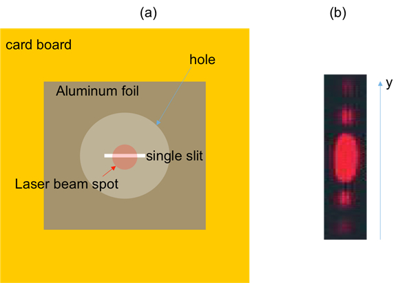
Next, take one piece of aluminum foil, and using a razor blade, cut a straight slit about 1 centimeter long in the middle of the foil. Tape the foil onto one cardboard with the slit positioned inside the hole.
Now, tape one edge of the cardboard to the wooden block and slide the white wall about 30 centimeters away from the slit. Make sure that the cardboard is perpendicular to the table surface, and the hole and vertical slit are exposed, and facing the wall.
Place the laser pointer on the other side of the mounted cardboard, while ensuring that the laser beam will be parallel to the table. Now wear the laser safety goggles, turn on the laser pointer, and shine the laser beam onto the slit.
Turn off the room light, and observe the light pattern on the wall on the other side of the foil. Turn OFF the laser pointer and remove the laser safety goggles.
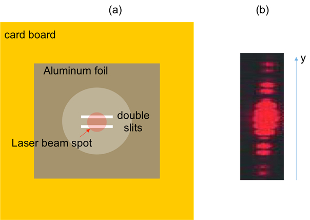
Next, stack three razor blades such that the middle blade is recessed. Take the other aluminum foil and using the stack of razor blades and a ruler cut two closely spaced straight parallel slits, about 1 centimeter long in the middle of the foil. Now tape the foil onto the other cardboard and then tape it onto the wooden block as before.
Wear the laser safety goggle, turn on the laser pointer, and shine the laser beam onto the double slit. Turn off the room light, and observe the light pattern on the wall on the other side of the foil. Finally, turn off the laser pointer.
With the protocol completed, let us now review the results of both the single-slit and the double-slit experiments. In the single slit experiment, the light pattern observed on the wall exhibits the characteristic diffraction fringes. The central bright fringe is approximately twice as wide, in the y-direction, as the other bright fringes which are all around the same width.
Additionally, the intensity of the bright fringes decay away from the center to the peripheral fringes along the y-axis. This is expected for the single slit diffraction pattern, as the parallel light rays from the laser bend at the slit and overlap constructively, forming the bright fringes and destructively forming the dark bands in between.
In the double slit experiment, the light pattern observed on the wall exhibits the characteristic interference fringes.
These interference fringes are much narrower than the bright regions of the diffraction pattern. This is because the inter-slit separation ‘d’ is much larger than the slit width ‘a’, and it is the reciprocal of the inter-slit separation that controls the width of the interference fringes. However, it is the reciprocal of the slit width ‘a’ that controls the width of the diffraction fringes.
The diffraction and interference of light has played an essential role in establishing that light is an electromagnetic wave. Thus, these effects are important in many technologies based on optics and photonics.
Laser diffraction spectroscopy, is a technology that utilizes diffraction patterns of a laser beam passed through any object — ranging from nanometers to millimeters in size — to quickly measure geometrical dimensions of a particle.
A sensor is used to detect the angling of the laser light and a computer is then used to detect the object’s particle sizes from the light energy produced and its layout.
Interferometry is a technique that uses superposition and interference of waves for the precise measurement of distances, small displacements, refractive index changes, and surface irregularities.
Here two waves of the same frequency, but different path length interfere, which results in an interference pattern. This pattern can then be used to make a precise measurement of the unknown parameter. This same technique of interferometry is used in the LIGO or Laser Interferometer Gravitational-Wave Observatory, which are huge detectors built to detect gravitational waves.
You’ve just watched JoVE’s introduction to diffraction and interference of light. You should now be able to understand the theory behind the formation of diffraction and interference light patterns, which was demonstrated using the single-slit and double-slit experiments. Thanks for watching!