Airplane wings, and their design, are essential to defining performance characteristics of an aircraft. The delta wing is a popular design in high-speed airplanes due to its excellent performance in transonic and supersonic flight regimes.
The delta wing has a small aspect ratio, which is defined as the wingspan divided by the average cord length. For a delta wing, this is 1/2 the root cord length. Other common wing designs, like the rectangular wing and the swept-tapered wing, have higher aspect ratios.
The delta wing also has a high sweep angle, which is defined as the angle between the 25% chord line and the lateral axis. These wing characteristics reduce drag at high subsonic, transonic, and supersonic flight regimes. Importantly, the delta wing has a high stall angle as compared to high aspect ratio wings.
In aerodynamics, the stall angle is the point at which the angle of attack is too high, causing lift to decrease. The high stall angle of a delta wing is due to enhanced lift by a leading-edge vortex over the wing, called vortex lift. Vortex lift occurs when a delta wing is subjected to higher angles of attack, which causes flow separation to take place at the leading edge of the wing, instead of occurring downstream near the trailing edge, as it would for a rectangular wing.
The roll up of the leading-edge vortices induces low pressure on the upper surface of the wing. This pressure differential enhances lift. These vortices start from the wing apex, and progress downstream. At some point, they burst, called vortex breakdown, due to the high adverse pressure gradient.
Once vortex breakdown happens, the vortex cannot induce low pressure anymore. At low angles of attack, the vortex breakdown occurs downstream of the trailing edge. However, as the angle of attack increases, the location of the vortex breakdown moves upstream until a point where the breakdown occurs over most of the wing surface. This reduces lift and causes the wing to stall.
In this experiment, we will use a water tunnel with dye to visualize these vortex patterns on a delta wing model and track the location of vortex breakdown at different angles of attack.
To conduct this experiment, you will need access to a water tunnel. First, obtain three 500-mL containers and fill each at least half full with dye. Use one container for blue dye, another one for green dye, and the last one for red dye.
The delta wing model used in our experiment has tubing already connected to the three dye containers. It also has three dye injection taps, which will disperse a different color dye at three different regions of the wing. Distance measurements are marked on the wing using 1-cm tick marks. The delta wing should already be attached to a C-strut support. Connect it to the tunnel with screws, keeping the yaw angle as close to 0 as possible.
Once the delta wing is in place, fill the water tunnel with water. Make sure you attach a paper with tick marks to provide a reference for the side view. Then, position a camera to capture the top view of the wing. Position a second camera to capture the side view. Now press ‘Record’ on each camera to capture footage of the dye injection and the subsequent vortices.
Manually set the angle of attack to 0 by adjusting the angle on the C-strut. Then, set the water tunnel flow speed to 4 in/s. Once the flow has stabilized, supply pressure to the dye reservoirs using the manual pump.
Observe the streaks of dye, then adjust the dye flow rate using the three knobs to generate a continuous streak. Applying all three colors at once enables us to view the vortex interactions at different regions of the wing. Observe the vortex interactions and identify the vortex roll up and the primary vortex core.
After you’ve recorded at least 10 seconds of the vortex, change the angle of attack to five degrees. Wait for the flow and streak lines to stabilize and record the vortices for at least 10 s.
Repeat the measurement by increasing the angle of attack in 5° increments up to 55°. Record at least 10 s of the streakline vortex pattern each time.
If the water becomes too murky, causing the streak lines to appear dull, close the dye supply and turn off the tunnel. Drain the water and replace it with fresh water before proceeding.
When all of the trials are finished, turn off the camera and close the dye supply. Then turn off the tunnel and drain the water. Be sure to wash the dye off of the tunnel when you are finished.
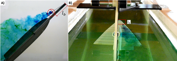
From the experiment, we can identify vortex breakdowns at different angles of attack. The distance from the wing apex to the vortex breakdown, labeled as LB, is measured, as shown. For simplicity, we reference this distance as a percentage of the chord length from the trailing edge.
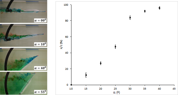
Now let’s look at the distance from the trailing edge to the vortex breakdown for each angle of attack. As shown here, the vortex breakdown location gradually moves upstream as the angle of attack increases. When the angle of attack equals 40°, the vortex breakdown occurs at 96% of chord location from the trailing edge. In other words, almost up to the apex of the wing. At this attitude, the delta wing experiences a full stall. In other words, it experiences a total loss of lift.
In summary, we learned how the low aspect ratio and high sweep angle of a delta wing contribute to its vortex lift and delayed stall. We then observed the vortex flow phenomenon on a model delta wing in a water tunnel, and used the vortex breakdown to estimate the stall angle.
 나눈다.
나눈다.