Recent findings suggest that bacterial flagellar motors sense a variety of environmental signals and remodel in response. The bead-assays discussed here are expected to help explain the role of remodeling in cellular adaptation to environmental stressors.
The role of flagellar motors in bacterial motility and chemotaxis is well-understood. Recent discoveries suggest that flagellar motors are able to remodel in response to a variety of environmental stimuli and are among the triggers for surface colonization and infections. The precise mechanisms by which motors remodel and promote cellular adaptation likely depend on key motor attributes. The photomultiplier-based bead-tracking technique presented here enables accurate biophysical characterization of motor functions, including adaptations in motor speeds and switch-dynamics. This approach offers the advantage of real-time tracking and the ability to probe motor behavior over extended durations. The protocols discussed can be readily extended to study flagellar motors in a variety of bacterial species.
Flagellar motors enable cells to swim by rotating helical extracellular filaments. The amount of torque the motor can generate for a given length of the flagellum (i.e., the viscous load) determines the swimming speeds. On the other hand, its ability to switch the direction of rotation controls cell migration in response to chemicals, a process known as chemotaxis. Chemotaxis and motility being virulence factors 1-3, flagellar motors have been well-characterized over the years 4. Mounting evidence now suggests that the motor acts as a mechanosensor — it mechanically detects the presence of solid substrates 5,6. This ability likely helps in triggering surface colonization and infections 5,7. As a result, the mechanisms whereby the motor senses surfaces and initiates signaling are of significance 8,9.
The flagellar motor can be readily studied by tethering the flagellum to a substrate and observing cell rotation. Such tethering was first achieved by Silverman and Simon, who worked with a polyhook mutant in E. coli and successfully attached hooks to glass substrates with anti-hook antibodies 10. The tethered-cell assay enabled researchers to study the responses of the motor-switch to a variety of chemical stimuli. For example, Segall and co-workers chemically stimulated tethered cells with the aid of iontophoretic pipettes. The corresponding changes in CWbias (the fraction of the time motors spin clockwise, CW) enabled them to measure the kinetics of adaptation in the chemotaxis network 11,12. While the tethered cell assay was effective in studying switch responses, it was only able to offer insights into motor mechanics over a limited range of viscous loads 13. To overcome this problem, Ryu and co-workers tethered spherical, latex beads to filament stubs on cells stuck to surfaces. The beads were then tracked using back-focal interferometry with weak optical traps 14. By working with beads of different sizes, researchers could study the motor over a much wider range of loads. This assay was later improved by Yuan and Berg, who developed a photomultiplier-based bead-tracking technique combined with laser dark-field illumination. Their method enabled tracking of tethered gold nanobeads that were so tiny (~ 60 nm) that the external viscous resistances were lower compared to the internal viscous resistances to rotation 15,16. This led to the measurements of the maximum achievable speeds in E. coli (~ 300 Hz). In V. alginolyticus, similar bead assays enabled measurements of the spinning rates at intermediate viscous loads (~ 700 Hz) 17. By enabling measurements of motor responses over the entire possible range of viscous loads (from zero-load to near-stall), the bead-assays provided an important biophysical tool to understand the torque-generation process 18,19.
Recently, we modified the Yuan-Berg assay to include optical tweezers that enabled us to apply precise mechanical stimuli to individual motors 6. Using this technique, we showed that the force-generators that rotate the motor are dynamic mechanosensors — they remodel in response to changes in viscous loads. It is possible that such load-sensing triggers cell differentiation into swarming bacteria, although the mechanisms remain unclear. It is also likely that the flagellar motors in other species are also mechanosensitive 20, although direct evidence is lacking. Here, we discuss the photomultiplier-based (PMT) approach for tracking the rotation of latex beads tethered to flagellar filaments 15. In comparison to tracking with ultrafast cameras, the photomultiplier-setup is advantageous because it is relatively straightforward to track single beads in real-time and over long durations. It is particularly useful when studying long-time remodeling in flagellar motor complexes due to environmental stimuli 21. Though we detail protocols specifically for E. coli, they can be readily adapted for studying flagellar motors in other species.
1. Cell Preparation
2. Slide Preparation
3. Bead Tracking
4. Data Analysis
The photomultiplier setup is shown in Figure 1A. It is important that the PMTs have high sensitivities over the range of wavelengths scattered by the beads of interest. The PMTs employed here operate in the visible and near-infrared ranges, and were able to detect light scattered by beads illuminated by a halogen light source. The optimum lighting conditions and supply voltages will vary from one setup to another. For the setup used in this work, a PMT gain ~ 104 – 105 proved adequate. Each photomultiplier was covered except for a 3 x 1 mm slit positioned in front of the photomultiplier. The slits limit the region in the cell-sample from which light can enter the photomultipliers, and the two slits are orthogonal to one another. When a rotating bead is positioned at the correct location (Figure 1B), the amount of light entering the photomultiplier increases as the bead comes in the view and decreases as its circular path takes it away from the view. The frequencies of the sinusoidal PMT voltage outputs indicate the speed of rotation and the phase differences between the two signals indicate the direction of rotation. The use of an oscilloscope to display the PMT outputs enables visualization of bead trajectories in real-time.
The time-varying PMT signals, y(t) and x(t), from a representative motor are shown in Figure 2A. The orthogonality of the two slits introduces a phase lag between the two signals. The signal amplitudes depend on the signal-to-noise ratio as well as the eccentricity of rotation. The corresponding trajectories of the bead are indicated in Figure 2B.
A histogram of the speeds measured from a representative motor in a cheY– deleted strain is shown in Figure 3A. The deletion ensures that flagellar motors cannot switch and rotate exclusively counterclockwise (CCW). The average speed from this particular motor was 60 Hz and the measured speeds are consistent with previous reports for motors tethered with 1 µm beads 25. The bead was first positioned at the lower right corner, as seen in the schematic in Figure 1B. The corresponding angular speed is shown in Figure 3B (top panel). Positioning the bead to the adjacent lower left corner resulted in inversion of the sign on the motor speeds (bottom panel). Thus, moving the bead to an adjacent corner will change the observed direction of motor rotation. In this regard, diagonally opposite corners are identical. It is therefore crucial to know the location of the bead during measurements to correctly determine the switching dynamics. Figure 3C shows repeated transitions of a wild-type motor between the two directions of rotation.
Custom codes for data-acquisition software were adapted from prior work to record the data on a computer 15. The PMT output was AC-coupled and low-pass filtered with a cutoff frequency of 100 Hz. Real-time tracking was enabled by connecting the filtered outputs to an oscilloscope.
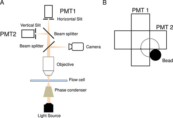
Figure 1: Bead-tracker Setup. A) Schematic of the PMT-based tracking setup. B) The ideal position of the bead (black sphere) relative to the two orthogonal slits. The trajectory is indicated by the dotted lines. The eccentricity e is the radius of the dotted circle. Please click here to view a larger version of this figure.
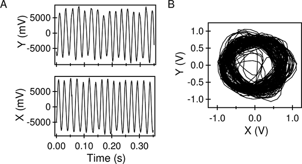
Figure 2: PMT Outputs. A) Low-pass filtered outputs from the two photomultipliers, after centering/scaling. B) The bead trajectories obtained from the PMT data, sampled over 3 s. Please click here to view a larger version of this figure.
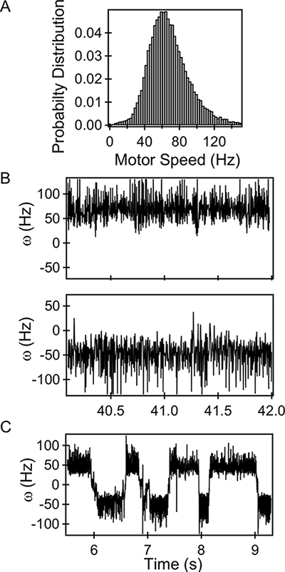
Figure 3: Bead Trajectories. A) Histogram of CCW-only speeds of a representative motor. B) Rotational speeds of a CCW-only motor imaged at lower right corner (top panel). Rotational speeds of the same motor when positioned at the lower left corner (bottom panel). C) Switching in a representative wild-type motor. Please click here to view a larger version of this figure.
In order to facilitate tethered bead-tracking and correct estimation of motor-torques, the following information should be reviewed. When performing these measurements with flagellated cells, shearing is a critical step. Shearing reduces the flagellar filament to a mere stub, thereby ensuring that the viscous load on the motor is predominantly due to the bead and can be estimated within 10% error 16. Shearing also improves the chances of finding circular trajectories with tightly distributed eccentricities (< bead diameter 14). Improper shearing results in wayward trajectories, which compounds errors in tracking and in the calculation of viscous drags, as well as resulting in poor signal-noise ratios. The use of an oscilloscope allows rapid elimination of such data. Since the biomechanical properties of flagellar filaments are expected to vary with species, shearing methods will likely need to be adapted to ensure adequate shearing in the bacteria of interest. An effective way of reducing errors associated with shearing is to work with cells that lack the genes that encode the filament proteins. Probe beads can then be attached directly to the hook via anti-hook antibodies.
Finding a bead that is appropriately tethered can be challenging. This is because most beads in the field of view will either be stuck to the cell bodies or the glass surface. Such beads can be readily brought into sharp focus. Other beads will appear to vibrate or rotate visibly with large amplitudes or large eccentricities (> 1.5 – 2x bead diameter). These are typically tethered to flagellar filaments that have not been fully sheared or rotate in a plane that is inclined to the focal plane. Sampling of such beads will typically result in higher noise, and time-variations in viscous loads may result in an underestimation of motors torques for a given bead-size. A small fraction of tethered beads will undergo random motion; these are merely undergoing Brownian rotation. A fraction of the beads will appear blurred and cannot be brought in focus easily. These are most likely to be motors which have been tethered appropriately and are the motors of interest.
Among the limitations of single-motor tracking such as the one described here is the inability to conduct high-throughput experiments. A high-speed camera that images a larger region of interest can be advantageous in this regard. Other limitations include errors associated with multiple signals arising out of closely spaced rotating beads in the field of view of the PMTs. Finally, errors in determination of the correct position of the recorded bead with respect to the two photomultiplier slits will result in imprecise estimation of the switching dynamics.
Advantages of the setup described here include the ability to track the rotation of the beads over long durations and in real-time. This enables rapid elimination of error-prone trajectories, something that maybe difficult to achieve with ultrafast cameras. Additionally, with a few modifications this setup can be integrated with assays designed to subject cells to a variety of stimuli. Combined with thermoelectric cooling 26, the technique can be employed to measure the responses of individual motors to thermal stimuli. Integration with optical tweezers can enable the measurements of remodeling of individual motors in response to mechanical stimuli, as has been done recently 6. Finally, the adaptation of the motor to chemical stimulants can be measured with the use of an appropriate perfusion chamber and pumps 11.
A majority of known bacterial species are motile and flagellar-mediated motility is predominant in nature. The methods demonstrated here are expected to continue to aid in the development of insights into structural-remodeling and the adaptability of the flagellar motor.
The authors have nothing to disclose.
The authors acknowledge Howard Berg for the gift of the bead-tracking microscope/photomultipliers and the Texas A&M Engineering Experiment Station for funds.
Poly-L-lysine Solution (0.1%) | Sigma-Aldrich | P8920 | http://www.sigmaaldrich.com/catalog/product/sigma/p8920?lang=en®ion=US |
Polybead Microspheres | Polysciences, Inc. | 7307 | http://www.sigmaaldrich.com/catalog/product/sigma/p8920?lang=en®ion=US |
1 ml Luer Slip Tip Syringe | Exel Int. | 26048 | http://www.exelint.com/tuberculin_syringes.php |
Clay Adams Intramedic Luer-Stub Adapter 23-gauge | Becton, Dickinson and Company | 427565 | http://www.bd.com/ds/productCenter/ES-LuerStubAdaptors.asp |
Polyethylene tubing | Harvard Apparatus | 59-8325 | http://www.harvardapparatus.com/laboratory-polye-polyethylene-non-sterile-tubing.html |
Photomultiplier Tubes | Hamamatsu | R7400U-20 | Spectral response range of 300 to 920 nm, Peak wavelength 630 nm, 0.78 ns response time http://pdf1.alldatasheet.com/datasheet-pdf/view/212308/HAMAMATSU/R7400U-20.html |
3×1 mm precision slits | Edmund Optics | NT39-908 | 2 slits mounted at right angles to one another on photomultiplier tubes |
Oscilloscope | Tektronix | TBS 1032B | Alternative brands are acceptable. Digital Oscilloscope, TBS 1000B Series, 2 Analogue, 30 MHz, 500 MSPS, 2.5 kpts http://www.tek.com/oscilloscope/tbs1000b-digital-storage-oscilloscope |
8 Pole LP/HP Filter | Krohn-Hite | 3384 | Alternative brands are acceptable. A frequency range from 0.1 Hz to 200 kHz is recommended. http://www.krohn-hite.com/htm/filters/PDF/3384Data.pdf |
Optiphot microscope | Nikon | NA | Any upright or inverted phase microscope can be used. https://www.thorlabs.com/newgrouppage9.cfm?objectgroup_id=754 |
50:50 (R:T) Cube Beamsplitter | ThorLabs | BS013 |