Our approach to fabricate the multi-depth microchannel network mimics the complex 3D geometries of in vivo microvessels, in which the microchannels have rounded cross sections15. Additionally, the diameters of parent branching channels and the daughter channels approximately obey Murray's law for maintaining the fluid flow at a required level so that the overall channel resistance is low and flow velocities are more uniform throughout the network16-18. The processes and results for the fabrication of a semicircular photoresist master mold and a circular cross-sectional PDMS microchannel network were demonstrated in Movie 1, Figure 2, and Movie 2, respectively. The geometric features of the PDMS microchannel network were characterized and shown in Figure 2. Our results show that the photoresist reflow technique can create multi-depth branching channel networks in a more convenient approach by photoresist reflow techniques, and allow designing the microvascular biomimetic systems which approximately obey Murray's Law.
In many in vitro models, vascular cells are normally cultured on planar plates, filters, or these substrates coated with hydrogels. Under these conditions the microvessels are randomly generated by cellular self-assembly. In addition, conventional assays have inherent difficulties in achieving a constant flow over endothelial cells. The lack of a long-term and continuous media flow prevents the ability to maintain the stability of endothelial cell monolayer with appropriate barrier functions. In our model, the benefit of applying microfluidics is the convenience for fluid access and control (varying flow rates, duration and patterns) as well as getting rid of waste. We demonstrate the processes for primary human umbilical vein endothelial cells (HUVECs) seeding in the microchannels and setting a long-term fluid perfusion system for cell culture (Figure 3). Furthermore, because of the complex geometries of in vivo microvasculature, real-time monitoring of those small vessels is difficult. The developed PDMS based chip offers good optical properties and allows for high-quality and real-time imaging of the endothelialized microchannels. (Figures 4 and Movie 3)
Movie 1. Schematic fabrication procedures for photoresist master molds. Initially, a pre-cleaned silicon substrate was prepared. The positive reflow photoresist layer was spin-coated onto the silicon substrate and was baked and dried. The photoresist was exposed to UV light through a patterned mask, and then, the patterned microchannels were developed. A semicircular cross-sectional microchannel network was created after the reflow at 120 °C for 4 min. Click here to view movie.
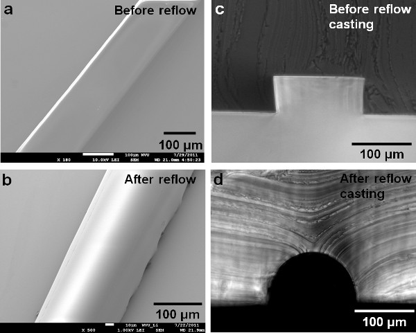
Figure 1. SEM shows the developed photoresist. a) before reflow; b) after reflow; c) molded PDMS shows the cross section of the resist before reflowing; the picture shows a rectangular cross section; d) molded PDMS showing a semicircular cross-section of the resist after reflowing; The cross section after reflow was controlled by the initial dimension design of the pattern and reflow temperature. (Reprinted with permission from Reference 15). Click here to view larger figure.
Movie 2. The schematic fabrication procedures for cylindrical microchannel network in PDMS. A PDMS solution was cast onto the photoresist mold and cured in the oven at a temperature of 60 °C for 3 hr. Two identical cured PDMS layers, each of which has a semicircular cross-sectional microchannel network, were aligned and bonded together to form microchannels with circular cross sections. Click here to view movie.
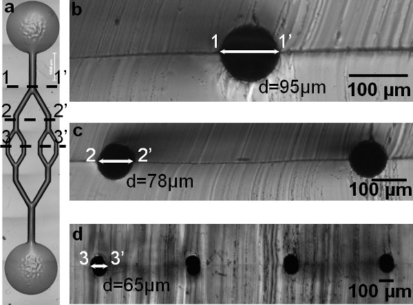
Figure 2. a) An aligned and bonded cylindrical microchannel network in PDMS. b-d) Circular cross-sections of PDMS molds show channel dimensions at each branching level (1-1', 2-2', and 3-3'). In addition, these figures show the creation of a multibranching and multidepth circular cross-sectional microfluidic channel network.
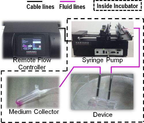
Figure 3. Schematic diagram showing the long-term perfusion through the chip using a remote controlled syringe pump.
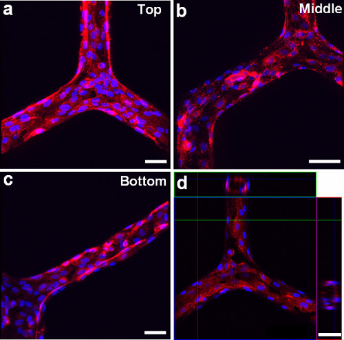
Figure 4. Microscopy images using fluorescent cell membrane dye (red) and cell nuclear dye (blue) show that the HUVECs line the inner surface of a cylindrical microchannel network at different branching regions. a) Top, b) Middle, and c) Bottom. d) Confocal microscopy image shows the circular cross-sectional view of HUVECs lining the channel network. Scale bars: 100 μm.
Movie 3. Confocal movie showing the cell lining along the circular channel network. Click here to view movie.
1. Master mold fabrication
One of the designing and guiding principles for vascular morphometry is known as Murray's law16, which states that the distribution of vessel diameters throughout the network is governed by minimum energy consideration. It also states that the cube of the diameters of a parent vessel at a bifurcation equals the sum of the cubes of the diameters of the daughter vessels ( )19 Additionally, Poiseuille's law has been used to estimate the magnitude of the shear stress in most of the vasculature as
  . in which
  is the hemodynamic shear stress, μ is the blood viscosity, Q is the flow rate, and R is the radius of the vessel20,21. For symmetric bifurcations, an important consequence based on Murray's law and Poiseuille's law is that the wall shear stress remains constant throughout the vascular network. Thus, for a fabricated symmetric microfluidic channel network with circular cross-sections, if the channel dimensions at bifurcations obey Murray's law, the shear stress experienced by the endothelial cells should be constant at different branching channels.
Many microfabrication techniques and processes have been applied to the fabrication of microchannels used for vascular cells22-25, however, the resulting microchannels resulted in rectangular, square or trapezoidal cross-sections of channels. The rectangular cross-sections of channels are constructed with sharp corners and abrupt transitions at bifurcations, which can impose widely varying fluid shear stresses and nonphysiological geometries on cells in different channel positions, thus resulting in variations in cell physiology26,27.
A photoresist reflow process, resulting in a rounded channel profile, involves two procedures, 1) the melting of the patterned photoresist and the liquid resist surfaces are pulled into a shape which minimizes the energy of the system28,29 and 2) a cooling and solidification phase follows the melting process. The shapes of the reflowed channels are well approximated by a semicylindrical surface. Followed by reflowed master mold fabrication, a standard soft lithography approach was used to fabricate the PDMS microfluidic channel network with a circular cross-section. Our results showed that the photoresist reflow technique can create multi-depth branching microchannel networks in a more straight forward approach, and allows us to design microvascular biomimetic systems that approximately obey Murray's Law and mimic the geometry of in vivo microvasculature, so that the overall channel resistance is low, and the shear stress variations at different branching levels can be minimized in the fabricated microfluidic channel network.
The physiologic blood microvessels adopt a roughly circular cross-section with radii between 30-300 μm30. The dimensions for the demonstrated microchannel network in this paper were varied around 60 μm to 100 μm at different branching levels. To fabricate microchannels with different range of diameters for mimicking in vivo microvessels, we recommend to use single spun layer reflow resist (limited to 30 μm) or other lower viscosity resists. For a microchannel with a larger diameter (30-60 μm), a double-coating procedure can be applied to get a thicker photoresist film15. Additional spin-coatings above two layers should be avoided to prevent nonuniform film thickness, which can result in an inaccurate exposure dose. For a film thickness above 60 μm, other higher viscous reflow photoresists are recommended.
In an ideal condition, to fabricate a resist mold with a semicircular cross section, the film thickness can be initially predetermined by giving a required width and focal length of the microchannel as  , where H is the required spun-film thickness, r is half of the channel width, R is the constant radius of curvature, h is the central height of the curvature, and E is the ratio of resist volumes of the microchannel before and after reflowing31. For a cylindrical surface of a given width of microchannel, one particular volume of the resist is required. However, several parameters have been reported to affect the reflowed photoresist and make the resulted channel profiles more complex, such as critical angle and boundary movement between the photoresist and the solid substrate, material evaporation during reflow baking, temperature and timing for the reflow process, outgassing, substrate uniformity, and resist properties32-34. For example, the reflow temperature and timing can result in a volume change causing the boundary movement and hence varying the critical angle and final reflowed resist profile 33. As reported by our previous work 15, the reflow process decreased the channel widths by 2% on average because of photoresist volume reductions and boundary movement. In addition, the volume for getting a cylindrical surface needs to make allowance for the effect of material evaporation during the reflow process 35,36. If cylindrical surfaces with different radii are required through a microchannel network it is necessary to vary the width of the microchannels, resulting in variations in the volumes at different regions in the network 15. To successfully fabricate a cylindrical channel network with different diameters, the resists widths/volumes, reflow temperatures and timing, critical angles, boundary movement, resist viscosities and spin coating protocols, and substrate properties must be considered and tested.
2. Long-term cell culture
The importance of flow and the associated wall shear stress has been well recognized in regulating endothelial biology. This has been seen in areas such as inducing changes in cell shape and orientation, secretion and organization, proliferation and differentiation, intracellular signaling, cytoskeleton protein production and gene expression, vessel maturation and structure, and barrier functions37-47. The current in vitro methods for forming endothelial tubes generally rely on endothelial cells' (ECs) self-organization with or without mesenchymal cells in extracellular matrix (ECM) (type I collagen, fibrin, or Matrigel)48-54. Although these cultures have successfully modeled several microvascular behaviors, the artificial vessels formed through a random process of morphogenesis lack the desired spatial reproducibility and orientation. Additionally, the impact of flow on microvascular stability remains largely unknown because these self-assembled vessels do not easily combine luminal flow with a 3D tubular organization55, posing a challenge to engineering blood vessels to have barrier functions and long-term vascular stability.
Microfluidic systems have proven to be practical and useful for introducing flows to a variety of biochemical and biological analysis56,57. Our approach provides a convenient way to introduce fluid flow over the cultured cells. We used an advanced remote controlled syringe pump to achieve a convenient yet steady and accurate flow control through the microchannels for long-term cell culture (between 4 days and 2 weeks).
3. Cell culture in the chip
Plasma-assisted oxidation of the PDMS microchannels introduces silanol groups (SiOH) on the surfaces which renders the surface hydrophilic and aids in further protein coatings. Different ECM proteins (fibronectin, gelatin, and collagen) were tested for cell attachment, and the best result was found to be fibronectin coating. The HUVECs were prepared at a concentration of 3 x 10⁶ cells/ml in culture media supplemented with 8% dextran (70 kDa) for seeding. Dextran increases the viscosity of the media to enable fine control over seeding density of ECs.
A confluent monolayer was developed between 2-4 days of the HUVECs being exposed to a constant medium flow. To visualize the cells after the cell culture, we labeled cells with membrane staining and nuclei staining dyes, these dyes exhibited lower cytotoxicity58. We stained the cells as an adherent monolayer cultured in the chip. A complete 1x PBS wash is necessary to prevent extra dyes trapped inside the chip.
In summary, by the combination of reflow photoresist technique and PDMS replication, the developed multi-depth microchannel network was approximated by a circular surface and the channel diameters at each bifurcation approximately obey Murray's law. The shear stress variations at different branching levels can be minimized in the fabricated microfluidic channel network. In addition, the results from cell culture indicated the healthy condition of the endothelial cells. Thus, the developed endothelialized microchannels-on-a-chip provides a rapid and reproducible approach to create circular cross-sectional multi-branching and multidepth microchannel networks, which mimics the geometry of in vivo microvessels. The procedure illustrates the use of unique capabilities in advanced micromanufacturing and microfluidic technologies to create a microvasculature model with a long-term, continuous perfusion control as well as high-quality and real-time imaging capability. With the increasing utility of microfluidic channels for cell biology, tissue engineering, and bioengineering applications, the endothelialized microchannels-on-a-chip is a potential assay for microvascular research.
