We demonstrate the use of patterned aerosol adhesives to construct 3D paper microfluidic devices. This method of adhesive application forms semi-permanent bonds between layers, enabling single-use devices to be non-destructively disassembled after use and to ease folding complex nonplanar structures.
We demonstrate the use of patterned aerosol adhesives to construct both planar and nonplanar 3D paper microfluidic devices. By spraying an aerosol adhesive through a metal stencil, the overall amount of adhesive used in assembling paper microfluidic devices can be significantly reduced. We show on a simple 4-layer planar paper microfluidic device that the optimal adhesive application technique and device construction style depends heavily on desired performance characteristics. By moderately increasing the overall area of a device, it is possible to dramatically decrease the wicking time and increase device success rates while also reducing the amount of adhesive required to keep the device together. Such adhesive application also causes the adhesive to form semi-permanent bonds instead of permanent bonds between paper layers, enabling single-use devices to be non-destructively disassembled after use. Nonplanar 3D origami devices also benefit from the semi-permanent bonds during folding, as it reduces the likelihood that unrelated faces may accidently stick together. Like planar devices, nonplanar structures see reduced wicking times with patterned adhesive application vs uniformly applied adhesive.
In recent years, paper microfluidics has garnered considerable popularity for its potential to provide low-cost point of care (POC) diagnostic devices.1-3 POC devices offer functionality similar to those of lab-based tests in a format that allows results to be obtained relatively quickly. POC devices made from paper are low-cost, lightweight, and easy-to-use alternatives to expensive microfluidic chips and miniaturized laboratories, making them ideal for use in resource-limited settings. The most common paper microfluidic devices are one-dimensional lateral flow devices, but planar three-dimensional (3D) paper microfluidic devices hold promise to provide multiplexed diagnostic devices4 that take up a much smaller footprint than would be required by a 2D device5 and correspondingly use a smaller sample volume.
Initially, planar 3D paper microfluidic devices were assembled individually, layer-by-layer with patterned paper layers alternating with laser-cut double-sided tape. Carefully aligned holes cut in the tape layer were filled with cellulose powder to ensure inter-layer fluid transport.4 A number of alternate methods were subsequently developed,6-9 each improving different aspects of the devices. In particular, by eschewing adhesives, devices could be folded via origami techniques with layers held together by an external clamp.8 This eliminates any potential adhesive interference in a diagnostic test and allows the device to be unfolded post-use, potentially allowing even smaller sample volumes by displaying results internally. Alternatively, by using an aerosol adhesive applied between each paper layer, sheets of devices could be assembled simultaneously, without time-consuming patterning and alignment of tape.9
However, by applying an aerosol adhesive through a stencil, it is possible to gain the benefit of both of these techniques. By spraying the adhesive through a stencil, only a fraction of the adhesive is applied to the device, minimizing any potential interference with interlayer fluid transfer. Additionally, with careful stencil selection, a pattern of adhesive can be applied that results in semi-permanent adhesive bonding, allowing devices to be unfolded after use, while still providing sufficient interlayer contact to allow fluid to wick between layers.
Finally, applying aerosol adhesives through a stencil eases the construction of nonplanar 3D paper microfluidic devices, by minimizing the amount of adhesive applied to adjacent faces that may require frequent folding and unfolding during construction.10 Additionally, the use of patterned adhesive enables device to be unfolded after use for more convenient storage. Nonplanar 3D paper microfluidic devices are expected to be used for tasks that would otherwise be impossible in a planar 3D device. Figure 1 depicts the general process flow used to construct both planar and nonplanar 3D devices.
1. Planar 4-layer Device (Stacked Layers) Construction
2. Planar 4-layer Device (Origami Folded Layers) Construction
3. Nonplanar (Origami) Device Construction
4. Wicking Test for 4-layer Devices
5. Origami Wicking Comparison
The 4-layer device tests were performed in a sealed chamber, shielding them from any wind or breezes that might cause excessive evaporation of the limited deposited fluid volume. The majority of the wicking in the 4-layer devices is in the middle layers of the device, so differences in wicking speeds due to evaporation were expected to be minimal. Additionally, there is minimal lateral wicking, with only 13 mm between the inlet and any individual outlet, suggesting that variations in wicking times are likely due to vertical, interlayer fluid transfer. Average wicking times and success rates for 4-layer devices constructed with different amounts of applied adhesive are shown in Table 1.
In stacked devices, uniform adhesive coverage resulted in relatively high success rates that decreased as we increased the quantity of adhesive. Patterned adhesive coverage resulted in very low success rates when adhesive was only applied to one side, but had much higher success rates and faster wicking times when the patterned adhesive was applied to both sides. Typical successes are depicted in Figure 3A. There are several potential explanations for this observed behavior, any combination of which may be applicable. The applied adhesive may be physically blocking, either partially or completely, the pores at the surface of the paper, resulting in a smaller effective contact area between paper layers. Also, the adhesive itself may act as another porous substrate, so heavier coatings of adhesive result in a thicker adhesive layer that fluid must wick through, leading to longer wicking times. Patterning the adhesive, on the other hand, creates adhesive 'dots' that only partially occlude the contact areas, allowing more fluid to wick from paper layer to paper layer directly, which decreases wicking times. However, this very reduction in adhesive coverage also decreases the strength of the adhesive bond between paper layers, resulting in decreased success rates when swelling fibers and unfolding creases cause layers to separate enough that they are no longer in contact. By doubling the size of the border around the channels (increasing the overall device area by ~30%), success rates for both single- and dual-sided adhesive applications increased. A comparison between the two sizes is shown in Figure 4. Typical stacked device failure was characterized by outlets that failed to completely fill with dye, or took longer than 5 min to fill. This is depicted in Figure 3B.
In origami folded devices, uniform adhesive coverage resulted in low success rates with complete failure resulting when applying the equivalent amount of adhesive present in the stacked, uniform, single-sided adhesive devices. Patterned adhesive coverage resulted in much lower success rates; however, this decrease was offset by using slightly larger devices that had 3 mm borders. Typical origami device failure was characterized by outlets that failed to fill with any amount of dye. These outlets were exclusively located along the two sides of the device that contained the creases. This is depicted in Figure 3C.
The masses of adhesive applied under different spray methods are shown in Table 2. The above-described spray duration of 1.33 sec (a four count at 180 bpm) deposits 0.26 mg/cm2 (dry mass) of adhesive when sprayed uniformly across the sheet of devices, while only depositing 0.02 mg/cm2 (dry mass) when sprayed through a stencil that was 23% open.
In nonplanar 3D structures, uniform adhesive coverage resulted in more difficult folding, as adjacent faces prematurely stuck together. The layers inside the structure could not be unfolded once the adhesive dried, and attempts to do so resulted in shredded paper. Patterned adhesive coverage made folding much easier, as any accidental adhesion was easily undone. Once the adhesive dried, the layers could be pulled apart without any ripping or tearing of the paper. Both methods of adhesive application resulted in devices that successfully routed liquid the length of their channels and without mixing; however, the device with uniformly applied adhesive was noticeably slower. A time-lapse of this wicking is shown in Figure 5. Wicking was performed in a humidity controlled chamber kept at >90% relative humidity to minimize evaporation, as evaporation increases with decreasing relative humidity. Due to the long channels present in this design, up to 165 mm long, evaporation can significantly increase the wicking time, even with an infinite fluid reservoir.
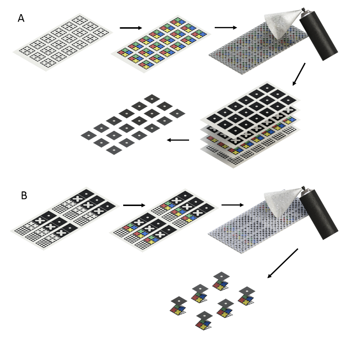
Figure 1. Device Fabrication Process Flow. (A) Stacked device fabrication. (B) Origami device fabrication. Please click here to view a larger version of this figure.
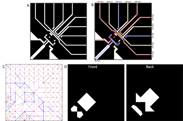
Figure 2. Peacock Patterns. (A) Channel pattern, where black indicates hydrophobic regions. (B) Arrows indicate the path taken by each dye. Circles indicate the point of contact between layers and the dotted lines indicate the vertical wicking paths. The length of each channel from its respective inlet to edge of the tail is indicated in millimeters. Channel widths averaged between 2 and 3 mm in the tail region. (C) Crease Pattern (modified from13). Red lines correspond to mountain folds in the final structure; black lines correspond to valley folds; blue lines correspond to creases that are not folded in the final structure, but aid in preliminary folding steps. (D) Masks placed between the origami device and the metal stencil during adhesive application, where the white portions are removed. Please click here to view a larger version of this figure.
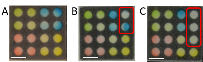
Figure 3. Typical Successes and Failures. (A) Typical Success — all outlets completely filled with dye. (B) Typical stacked failure — outlets that failed had no apparent pattern in their distribution. (C) Typical origami failure — all outlets that failed to fill were located along the left-most or right-most column, closest to the creases. All scale bars are 5 mm. Please click here to view a larger version of this figure.
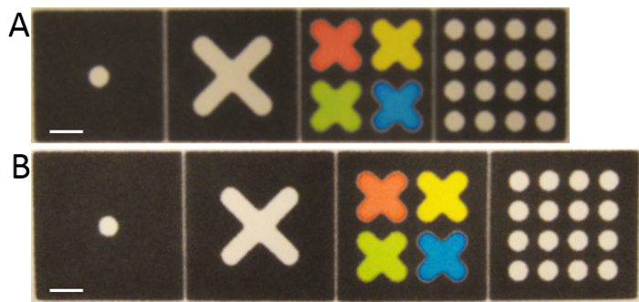
Figure 4. Device Size Comparison. (A) Smaller device (1.6 mm border). (B) Larger device (3 mm border). All scale bars are 5 mm. Please click here to view a larger version of this figure.
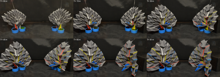
Figure 5. Time Lapse of Origami Peacock. Left: uniform adhesive coverage. Right: patterned adhesive coverage. Please click here to view a larger version of this figure.
Device Style | Adhesive Type (Duration/Border/Sides) | Average ± SD (sec) | Success Rate |
Origami | Uniform (1.33 sec / 1.6 mm / Double) | 44 ± 14 | 45% |
Uniform (0.67 sec / 1.6 mm / Double) | 0 ± 0 | 0% | |
Patterned (1.33 sec / 1.6 mm / Double) | 41 ± 13 | 15% | |
Patterned (1.33 sec / 3 mm / Double) | 64 ± 50 | 40% | |
Stacked | Uniform (1.33 sec / 1.6 mm / Single) | 152 ± 66 | 80% |
Uniform (1.33 sec / 1.6 mm / Double) | 119 ± 68 | 60% | |
Patterned (1.33 sec / 1.6 mm / Single) | 164 ± 75 | 25% | |
Patterned (1.33 sec / 1.6 mm / Double) | 81 ± 25 | 80% | |
Patterned (1.33 sec / 3 mm / Single) | 116 ± 63 | 85% | |
Patterned (1.33 sec / 3 mm / Double) | 80 ± 55 | 100% |
Table 1. Four Layer Device Performance. Average wicking time and success rates for different adhesive application conditions. N=20.
Adhesive Coverage | Spray Duration (sec) | Average Mass ± SD (mg/cm²) |
Uniform | 1.33 | 0.26 ± 0.05 |
Uniform | 0.67 | 0.14 ± 0.03 |
Patterned | 1.33 | 0.02 ± 0.01 |
None | 0 | -0.01 ± 0 |
Table 2. Applied Adhesive Amounts. Average adhesive thickness (dry mass) applied over a 9×9 cm square under different spray conditions. N=10.
The above protocols use perforated metal sheets as stencils for applying aerosol adhesives to construct planar and nonplanar 3D paper microfluidic devices. In planar devices, this has the advantage of allowing devices to be completely unfolded after the adhesive has dried without destroying the device. In other adhesive based construction techniques, this is almost impossible, although, some designs allow for partial destructive disassembly by unpeeling two halves held together with a removable adhesive.14 Adhesiveless construction does allow devices to be unfolded after use, but requires custom clamps or housings for each device.8
In devices with primarily lateral wicking, adhesives can significantly slow wicking. By patterning the adhesive, the amount of adhesive applied to the wicking regions can be significantly reduced, limiting any potential wicking interference. Devices with predominantly vertical wicking also exhibit similarly slow wicking caused by adhesive, although to a much lesser extent. Design of a stencil that completely blocks out all wicking regions, limiting adhesive application to hydrophobic regions only, may eliminate any potential wicking interferences, but may also add considerable alignment time to the construction process.
In nonplanar devices, the patterned adhesive dramatically eases folding, as the quantity of adhesive that is applied to the paper is decreased, making folding significantly easier than with a uniformly applied adhesive layer. Paper completely covered in adhesive is far more difficult to fold when any incidental contact between different areas of the paper causes adhesion that must be undone before continuing.
For planar 3D multilayer devices that have a large wicking area relative to the hydrophobic area, origami folding paired with an aerosol adhesive is likely not the optimal construction technique due to the adhesive's inability to hold wetted paper layers together while overcoming the tendency of the creases to unfold. Devices with designs that include sufficient hydrophobic borders will increase the success rate of origami-folded devices. Using a stronger bond-strength adhesive may also help to solve this issue, preventing water from weakening the paper-adhesive bond.
Stacked layer devices overall performed better, as they lack creases, which tend to unfold the device. Further, the use of a stencil during adhesive application reduces the total amount of adhesive applied, dramatically reducing the time required for fluid to wick between layers.
In designing nonplanar 3D paper microfluidic devices, there are a number of issues to consider. It is important to compare the crease pattern of the folded device to the layout of the channels, as placing channels along a crease will force the crease open upon water imbibition, due to swelling cellulose fibers. Depending on the design of the specific device, though, this may or may not be desired behavior. Device storage at ambient conditions is not favorable to device viability,10 thus long-term storage under dry air is recommended to prevent the adhesive bond between layers from weakening.
As previously noted by Lewis et al.,9 the use of aerosol adhesives provide an efficient means to rapidly produce large quantities of 3D paper microfluidic devices. By patterning such adhesives, new devices can be more rapidly developed that take advantage of being able to be unfolded after use.
Further, patterning enables the construction and development of nonplanar 3D paper microfluidic devices. Such devices are expected to be able to provide functionality not previously found in planar paper microfluidics, such as integrated actuation and sensing. For example, actuation can be achieved by creating a bilayer from a water reactive polymer film15 and a patterned paper substrate. In a device constructed from such a bilayer, actuation would be generated when water wicks along the device's channels and interacts with the film. Once the film dries, the device would return to its initial configuration, leaving it ready to be used again.
The authors have nothing to disclose.
This work is supported by a fund from Bourns College of Engineering of University of California, Riverside. BK received a scholarship from the Lung-Wen Tsai Memorial Award in Mechanical Design.
Camera | Nikon | D5100 | |
Solid-ink printer | Xerox | ColorQube 8880 | |
Hotplate | Torrey Pines | HS60 | |
Humidity chamber | Electro-Tech Systems | 5503-E | |
Spray adhesive | 3M | 62497749309 | Super 77 (16.75 oz can) |
Filter paper | Whatman | Grade 4 | |
Perforated steel sheet | MetalsDepot | PS16116 | |
Tartrazine | Sigma-Aldritch | T0388 | |
Allura Red | Sigma-Aldritch | 458848 | |
Erioglaucine disodium salt | Sigma-Aldritch | 861146 |