The evaluation of tissue development in the fracture callus during endochondral bone healing is essential to monitor the healing process. Here, we report the use of a magnetic resonance imaging (MRI)-compatible external fixator for the mouse femur to allow MRI scans during bone regeneration in mice.
Endochondral fracture healing is a complex process involving the development of fibrous, cartilaginous, and osseous tissue in the fracture callus. The amount of the different tissues in the callus provides important information on the fracture healing progress. Available in vivo techniques to longitudinally monitor the callus tissue development in preclinical fracture-healing studies using small animals include digital radiography and µCT imaging. However, both techniques are only able to distinguish between mineralized and non-mineralized tissue. Consequently, it is impossible to discriminate cartilage from fibrous tissue. In contrast, magnetic resonance imaging (MRI) visualizes anatomical structures based on their water content and might therefore be able to noninvasively identify soft tissue and cartilage in the fracture callus. Here, we report the use of an MRI-compatible external fixator for the mouse femur to allow MRI scans during bone regeneration in mice. The experiments demonstrated that the fixator and a custom-made mounting device allow repetitive MRI scans, thus enabling longitudinal analysis of fracture-callus tissue development.
Secondary fracture healing is the most common form of bone healing. It is a complex process mimicking specific aspects of ontogenic endochondral ossification1,2,3. The early fracture hematoma predominantly consists of immune cells, granulation and fibrous tissue. Low oxygen tension and high biomechanical strains hamper osteoblast differentiation at the fracture gap, but promote the differentiation of progenitor cells into chondrocytes4,5,6. These cells start to proliferate at the site of injury to form a cartilaginous matrix providing initial stability of the fractured bone. During callus maturation, chondrocytes become hypertrophic, undergo apoptosis, or trans-differentiate into osteoblasts. Neovascularization at the cartilage-to-bone transition zone provides elevated oxygen levels, allowing the formation of bony tissue7. After bony bridging of the fracture gap, biomechanical stability is increased and osteoclastic remodeling of the external fracture callus occurs to gain physiological bone contour and structure3. Therefore, the amounts of fibrous, cartilaginous, and bony tissue in the fracture callus provide important information about the bone healing process. Disturbed or delayed healing becomes visible by alterations of callus tissue development both in humans and mice8,9,10,11. Available in vivo techniques to longitudinally monitor callus tissue development in preclinical fracture healing studies using small animals include digital radiography and µCT imaging12,13. However, both techniques are only able to discriminate between mineralized and non-mineralized tissue. In contrast, MRI provides excellent soft tissue contrast and might therefore be able to identify soft tissue and cartilage in the fracture callus.
Previous work showed promising results for post mortem MRI in mice with articular fractures14 and in vivo MRI in mice during intramembranous bone-defect healing15. However, both studies also stated limited spatial resolution and tissue contrast. We previously demonstrated the feasibility of high-resolution in vivo MRI for longitudinal assessment of soft callus formation during murine endochondral fracture healing16. Here, we report the protocol for using an MRI-compatible external fixator for femur osteotomy in mice in order to monitor callus tissue development longitudinally during the endochondral fracture healing process. The design of a custom-made mounting device for insertion of the external fixator ensured a standardized position during repeated scans.
All animal experiments complied with international regulations for the care and use of laboratory animals and were approved by the regional regulatory authorities (No. 1250, Regierungspräsidium Tübingen, Germany). All mice were maintained in groups of two to five animals per cage on a 14-h light, 10-h dark circadian rhythm with water and food provided ad libitum.
1. Preparation of the Surgical Material and Pre-treatment of the Mice
2. Surgical Procedure and Application of the External Fixator
3. MRI Procedure and Image Analysis
First, the success of the surgical procedure can be confirmed by analysis of the MRI scans (see example in Figure 2). All four pins should be located in the middle of the femoral shaft. The size of the osteotomy gap should be between 0.3-0.5 mm. If the size of the osteotomy gap varies greatly from these values, the mouse should be excluded from further analysis.
Secondly, the evaluation of longitudinal scans during the fracture healing process in the same animal provides information about callus tissue development. If mice are scanned at day 10, 14, and 21 (see example in Figure 3), cartilaginous tissue is visible in the middle of the fracture callus on day 10 (relative cartilage area = 30.8%) and day 14 (relative cartilage area = 29.0%), and decreases until day 21 after surgery (relative cartilage area = 10.5%) (Figure 3). Bony tissue is visible at the periphery of the fracture callus on day 10 (relative bone area = 7.2 %), increases until day 14 (relative bone area = 15.6%), and body bridging occurs until day 21 (relative bone area = 45.7%).
Thirdly, after segmentation of the different tissues in the fracture callus using image analysis software, 3D images from the fractured femur and the fracture callus can be generated. In the example shown in Figure 4, a whole femur scanned on day 26 after fracture is displayed. Mature cortex is marked in grey, the ceramic pins are marked in yellow, callus soft tissue is marked in green, cartilage tissue is marked in red, and callus bony tissue is marked in purple.
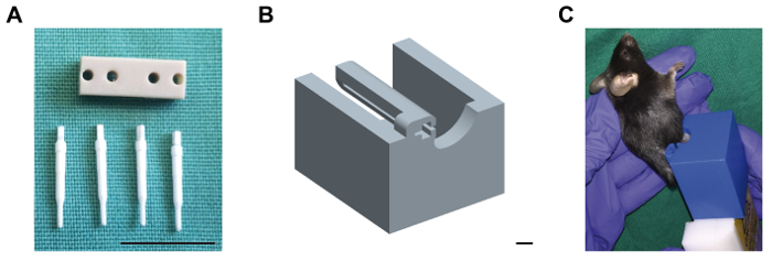
Figure 1: External fixator with ceramic mounting pins and MRI mounting device. (A) The plastic body of the external fixator is shown, as well as the four ceramic mounting pins which are compatible to MRI scans. Scale bar: 1 cm. (B) The computer-aided drawing of the custom-made mounting device for insertion of the external fixator during MRI scans is shown. The external fixator at the right femur of the mouse is inserted into the relief of the mounting device. Then, the device is plugged on the four-element head coil prior to scanning. Scale bar: 0.4 cm. (C) Mouse placed in the mounting device (blue), attached to the 4-element head coil (white). Please click here to view a larger version of this figure.
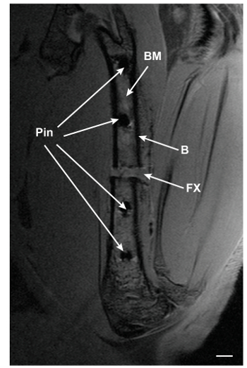
Figure 2: PD-TSE MRI image of a fractured femur 3 days after surgery. A central slice of a fractured femur scanned on day 3 after surgery is shown. BM: bone marrow; B: bone; FX: fracture gap. Scale bar: 0.5 mm. Please click here to view a larger version of this figure.
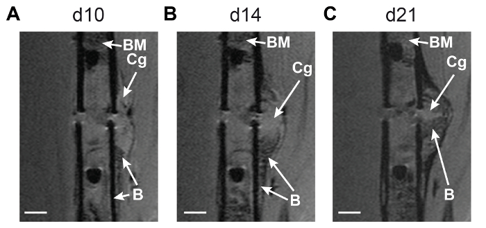
Figure 3: Longitudinal monitoring of fracture callus development using MRI technique. Central MRI slices from the fractured femur of one mouse scanned on (A) day 10, (B) day 14, and (C) day 21 after surgery are displayed. Hyper-intense cartilaginous tissue is visible in the middle of the fracture callus on day 10 and day 14, and decreases until day 21 after surgery. Hypo-intense bony tissue is visible at the periphery of the fracture callus on day 10, increases until day 14, and body bridging occurs until day 21. BM: bone marrow; Cg: cartilaginous tissue; B: bony tissue. Scale bar: 0.5 mm. Please click here to view a larger version of this figure.
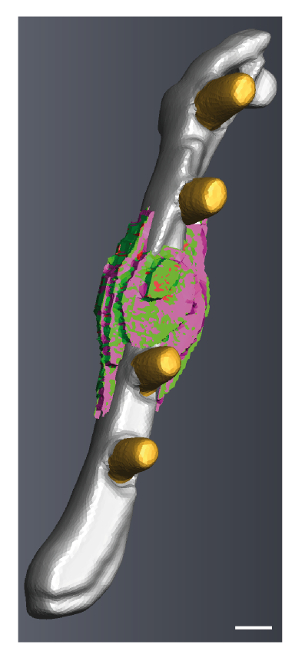
Figure 4: 3D reconstruction from a fractured femur scanned on day 26 after surgery. Mature cortex is marked in grey, the ceramic pins are marked in yellow, callus soft tissue is marked in green, cartilage tissue is marked in red, and callus bony tissue is marked in purple. The image was generated using image analysis software. Scale bar: 0.4 mm. Please click here to view a larger version of this figure.
Modifications and Troubleshooting:
The main goal of this study was to describe a protocol for using of an MRI-compatible external fixator for femur osteotomy in the mouse with the ability to monitor callus tissue development longitudinally during the endochondral fracture-healing process. The design of a custom-made mounting device for insertion of the external fixator ensured a standardized position during repeated scans. Semi-automatic tissue segmentation allows the analysis of the amounts of fibrous, cartilaginous, and bony tissue in the fracture callus. Furthermore, 3D reconstructions of the MRI images allow visualization of the endochondral fracture healing process in each individual mouse.
Critical Steps Within the Protocol:
The most critical steps of the surgical procedure using the MRI-compatible external fixator are: (1) Avoid any damage to the sciatic nerve during the surgery, otherwise the mouse will not be able to weight bear within 5 days after the osteotomy and must be excluded from further analysis. (2) Avoid tension, compression, or shear stress on the fixator during the mounting procedure, otherwise the osteotomy gap will not have a standardized size and shape. Furthermore, make sure to mount the fixator parallel to the longitudinal axis of the femur, ensuring a stable fixation of the osteotomy. (3) Avoid metal chips from the saw if using a gigli wire saw, since those will interfere with the MRI scanning procedure.
The most critical steps of the MRI scanning procedure are: (1) Make sure to avoid bending or compression of the fixator during insertion and removal of the mounting device as this may interfere with fracture healing. (2) Ensure proper temperature control during the scanning procedure to maintain physiological body temperature.
Significance with Respect to Existing Methods and Limitations of the Technique:
Previous studies showed promising results for post mortem MRI in mice with articular fractures14 and in vivo MRI in mice with intramembranous bone-defect healing15. However, both studies also stated limited spatial resolution and tissue contrast. We previously demonstrated the feasibility and accuracy of high-resolution in vivo MRI for longitudinal analysis of soft callus formation during the early and intermediate phases of fracture healing in mice by comparing the new MRI technique with the gold standards µCT and histomorphometry16. However, we also found that the spatial resolution of MRI is significantly lower than the resolution of ex vivo µCT. This is a clear limitation of the MRI technique when compared to competing techniques, including ex vivo but also in vivo µCT.
Future Applications:
Future perspectives for the use of MRI during murine fracture-healing studies are: (1) Combination of MRI scans with the use of contrast agents to measure blood flow through the injured limb. (2) Combination of MRI and PET scans, as well as labeling of cells with superparamagnetic particles of iron oxide for cell trafficking experiments17,18,19,20.
The authors have nothing to disclose.
We thank Sevil Essig, Stefanie Schroth, Verena Fischer, Katja Prystaz, Yvonne Hägele, and Anne Subgang for excellent technical support. We also thank the German Research Foundation (CRC1149, INST40/499-1) and the AO Trauma Foundation Germany for funding this study.
Anaesthesia tube | FMI, Seeheim, Germany | ZUA-82-ANA-TUB-Mouse | |
Anaesthetic machine | FMI, Seeheim, Germany | ZUA-82-GME-MA | |
Artery forceps | Aesculap, Tuttlingen, Germany | BH104R | |
Autoclave | Systec, Wettenberg, Germany | DX-150 | |
Autoclaving packaging | Stericlin, Feuchtwangen, Germany | 2301-04/06/10/12/16 | |
Avizo software | FEI, Burlington, USA | – | Version 8.0.1 |
BioSpec 117/16 magnetic resonance imaging system | Bruker Biospin, Ettlingen, Germany | 117/16 | |
Bulldog clamp | Aesculap, Tuttlingen, Germany | BH 021R | |
Carbon steel scalpel no. 11/15 | Aesculap, Tuttlingen, Germany | BA211/215 | |
Ceramic mounting pin 0.45 mm | RISystem, Davos, Switzerland | HS691490 | |
Clindamycin (300 mg / 2ml) | Ratiopharm, Ulm, Germany | – | |
Dressing forceps 115 mm | Aesculap, Tuttlingen, Germany | BD210R | |
Dressing forceps 130 mm | Aesculap, Tuttlingen, Germany | BD025R | |
Drill bit coated 0.45 mm | RISystem, Davos, Switzerland | HS820420 | |
Durogrip needle holder 125 mm | Aesculap, Tuttlingen, Germany | BM024R | |
Foliodrape | Hartmann, Heidenheim, Germany | 2513026 | |
Frekaderm | Fresenius, Bad Homburg, Germany | 4928211 | |
Gigli saw 0.44 mm | RISystem, Davos, Switzerland | RIS.590.110.25 | |
Hand drill | RISystem, Davos, Switzerland | RIS.390.130-01 | |
Heating plate | FMI, Seeheim, Germany | IOW-3704 | |
Hygonorm gloves | Hygi, Telgte, Germany | 2706 | |
Isoflurane | Abbot, London, UK | Forene | |
Micro forceps 155 mm | Aesculap, Tuttlingen, Germany | BD343R | |
Micro scissors 120 mm | Aesculap, Tuttlingen, Germany | FD013R | |
Mouse FixEx L 0.7 mm | RISystem, Davos, Switzerland | RIS.611.300-10 | |
Needle case for drills | Aesculap, Tuttlingen, Germany | BL911R | |
Needle holder | Aesculap, Tuttlingen, Germany | BB078R | |
Octenisept | Schülke, Norderstedt, Germany | 121403 | |
Osirix software | Pixmeo SARL, Bernex, Switzerland | – | Version 4.0 |
Oxygen, medical grade | MTI, Ulm, Germany | – | |
Resolon 5/0 | Resorba, Nürnberg, Germany | 88143 | |
Saline 0.9% | Braun, Melsungen, Germany | 3570350 | |
Scalpel handle 125 mm | Aesculap, Tuttlingen, Germany | BB073R | |
Scissors 150 mm | Aesculap, Tuttlingen, Germany | BC006R | |
Sealer for autoclave packaging | Hawo GmbH, Obrigheim, Germany | HM500 | |
Sterican 27 G | Braun, Melsungen, Germany | 4657705 | |
Sterile surgical blades no. 11/15 | Aesculap, Tuttlingen, Germany | BB511/515 | |
Surgical gloves | Hartmann, Heidenheim, Germany | Peha-micron 9425712 | |
Surgical light | Maquet SA, Ardon, France | Blue line 80 | |
Syringes 5 ml | Braun, Melsungen, Germany | Injekt 4606051V | |
Tissue forceps 80 mm | Aesculap, Tuttlingen, Germany | OC091R | |
Tramadol 25 mg/l | Grünenthal, Aachen, Germany | 100mg/ml | |
Vasofix Safety | Braun, Melsungen, Germany | 4268113S-01 | |
Vicryl 5-0 | Ethicon, Norderstedt, Germany | V30371 | |
Visdisic eye ointment | Bausch & Lomb, Berlin, Germany | 3099559 |