In this paper, a method for measuring radiance in situ in living tissue is described. This work includes details of the construction of micro-scale probes for different measurements of radiance and irradiance, provides guidance for mounting tissue for the characterization of radiance, and outlines computational methods for analyzing the resulting data.
Organisms appear opaque largely because their outer tissue layers are strongly scattering to incident light; strongly absorbing pigments, such as blood, typically have narrow absorbances, such that the mean free path of light outside the absorbance peaks can be quite long. As people cannot see through tissue, they generally imagine that tissues like the brain, fat, and bone contain little or no light. However, photoresponsive opsin proteins are expressed within many of these tissues, and their functions are poorly understood. Radiance internal to tissue is also important for understanding photosynthesis. For example, giant clams are strongly absorbing yet maintain a dense population of algae deep in the tissue. Light propagation through systems like sediments and biofilms can be complex, and these communities can be major contributors to ecosystem productivity. Therefore, a method for constructing optical micro-probes for measuring scalar irradiance (photon flux intersecting a point) and downwelling irradiance (photon flux crossing a plane perpendicularly) to better understand these phenomena inside living tissue has been developed. This technique is also tractable in field laboratories. These micro-probes are made from heat-pulled optical fibers that are then secured in pulled glass pipettes. To change the angular acceptance of the probe, a 10-100 µm sized sphere of UV-curable epoxy mixed with titanium dioxide is then secured to the end of a pulled, trimmed fiber. The probe is inserted into living tissue, and its position is controlled using a micromanipulator. These probes are capable of measuring in situ tissue radiance at spatial resolutions of 10-100 µm or on the scale of single cells. These probes were used to characterize the light reaching the adipose and brain cells 4 mm below the skin of a living mouse and to characterize the light reaching similar depths within living algae-rich giant clam tissue.
Surprisingly, land animals and shallow ocean dwellers have enough light within their body for visual physiology and even photosynthesis. For example, the light levels in the center of a mouse's head (outside of the strong hemoglobin absorbance bands) are attenuated by three or four orders of magnitude relative to the outside world. This is roughly the difference between the light levels indoors and outside. So, the opacity of a tissue or material due to strong scattering is not the same as opacity due to strong light absorption. Light can keep propagating over long distances in a strongly forward-scattering system, similar to light propagating through aquatic systems with high concentrations of cells and particles1. This observation is particularly salient in light of the fact that opsin proteins are near-ubiquitously expressed in all tissues of all animals. Thus, it is important to understand how and where light is attenuated and scattered within living tissue. However, unlike aquatic systems, with living tissue, it is impossible to immerse an instrument in the water column and obtain radiance and irradiance measurements, and a new technique is necessary.
Other methods previously used to characterize the absorption and scattering properties of living tissue include measuring tissue reflectance probes and/or integrating spheres2,3, microscopic methods such as scanning confocal microscopy4, measuring the diffusion of laser light on the surface5, and modeling techniques such as Monte Carlo radiative transfer6. The experimental methods mentioned often require specific, large, and expensive equipment or detailed knowledge about tissue structure and are generally limited in their ability to characterize the spatial structure of light deep within the tissue.
There are also similar probe-based methods that use a hypodermic needle to insert an optical fiber through tissue7,8,9. In our experience, modified needles are effective at puncturing tissue but require considerable force and generally tear delicate tissues when passaging through densely packed cells. Therefore, these needles generally require a surgical procedure to insert more than a millimeter or so into a tissue layer. The method described here, using a lubricated, pulled glass support, is capable of sliding between cells with minimal wounding of the tissue and without additional surgery.
This manuscript presents a method inspired by the work of Jorgenson and colleagues on measuring light within algal mats10,11, using glass-supported optical microprobes and portable electronics that are amenable to probing deep into dense tissue and to construction and use in the field. These probes can be constructed to characterize scalar irradiance (light hitting a point from all directions) and downwelling radiance (light intersecting a horizontal plane) inside living tissue at high spatial resolutions. These probes were originally developed to measure radiative transfer within the tissue of photosymbiotic giant clams12. Standard measurements of absorption and transmission of the total tissue were not enough to characterize the photosynthetic performance of the tissue, since it makes a big difference whether all the incident light is absorbed by a few cells experiencing high intensity at the surface of the tissue or many cells experiencing low intensities throughout the volume of the tissue. In a second project, these probes were used to measure in vivo irradiance within a mouse's brain13,14, thereby characterizing the light environment of opsins expressed deep within the brain. These micro-probes are both small and sensitive enough to measure irradiance within mouse brain tissue with all the fur, skin, and bone intact and demonstrate that physiological light levels are easily high enough to stimulate deep-brain opsins.
This micro-optical probe and measuring setup could be useful to researchers needing to quantify and characterize the light internal to biological tissue, particularly for a more nuanced understanding of photosynthesis or the functions of visual pigments expressed outside of the eyes. This method can be used alone or in conjunction with other techniques to fully characterize the optical properties and light propagation within living tissue at a low cost, with small portable equipment built in-house and with task-dependent adjustable parameters.
This study is compliant with all the relevant ethical regulations of Yale University regarding vertebrate and invertebrate animal research.
1. Building the optical micro-probe
2. Preparing and mounting the tissue for optical measurements (Figure 2 and Figure 3)
3. Measurement setup for tissue biopsies
4. Data collection
This protocol describes the procedure for constructing a micro-optical probe that can be used to measure the downwelling irradiance (the light reaching a point from one direction) or, with the addition of a light-scattering spherical tip, to measure the scalar irradiance (the light reaching a point from all directions). These probes can measure irradiance at spatial resolutions approaching the length scales of single cells inside living tissue. This protocol also describes a representative method for preparing a tissue sample for irradiance measurements using the described probe and a representative method for data viewing and analysis.
Figure 1 shows the output of micro-probe production. When pulled, the optical fiber should taper for about 3 cm and not have any scratches along the taper. It should also be flat at the end and have a diameter of 15-30 µm (Figure 1D). The flatness of the tip can be improved by sanding the end with carborundum paper or scoring and breaking again. Similarly, the pulled glass pipette used as the fiber's housing should not have any sharp or broken edges. When the scattering ball is formed on the end of the fiber's flat, cut tip, it should be spherical (Figure 1C). Before curing, misshapen ones can be removed by another round of inserting the ball into the parent adhesive droplet and quickly pulling the fiber out. A fast speed of movement will pull the ball of glue from the end of the fiber. Slower movements result in additional adhesive building on the fiber. Watching the process using a dissecting microscope while the fiber is attached to a light source is helpful for visualizing the work and determining if the process is working. It is important to secure the fiber inside the glass pipette with glue and electrical tape before applying the scattering adhesive; otherwise, the fiber may break, or the adhesive may smear with the shifting fiber (Figure 1).
Figure 2 shows the measurement apparatus. In this example, the holders for both the tissue sample and the probe have adjustment capabilities in three dimensions (Figure 2). Attaching both the sample and the probe to manipulators helps with the alignment but is not essential; the probe could be attached to a stationary post. The most resolved movements of the manipulators should be oriented in the vertical, z-direction so that position in the tissue and/or the amount the probes moves can be accurately determined (Figure 2A). A boom-mounted stereomicroscope can be useful when placed such that one can view the stage, probe, and sample through the eyepiece to check the alignment of the probe with the stage, dish, and sample (Figure 2B). Watching the spectra in real-time while lowering the sample onto the probe is helpful because if the spectrum measured by the probe suddenly changes, this suggests that the sample is successfully located inside the highly scattering or absorbing tissue or that the probe is bending or breaking. Abrupt shifts in the shape and intensity of the spectrum most likely indicate tissue entrance, while abrupt intensity changes without a change in shape suggest that the probe is bending or breaking. At the top of the clam tissue, there is a thin clear membrane that the probe cannot penetrate without breaking. In a case like this, the top of the tissue should be monitored to see when the probe is about to exit, and the measurements should be stopped at that point so that the probe does not break.
Figure 3 shows the tissue biopsy sample embedded in a Petri dish of gelatin, as described in section 2. There is a hole in the bottom of the Petri dish to allow the optical probe's insertion into the tissue from underneath. The biopsy is 8 mm in diameter and centered over the hole in the Petri dish (Figure 3A). There is a small amount of gelatin below the tissue sample, and the gelatin is filled to the top of the dish above the tissue (Figure 3B).
Figure 4A shows the probe as its starts to exit the top of the tissue, and Figure 4B shows the representative data. A Matlab script (Supplementary File 2) was used to generate the traces in Figure 4B. The x-axis is the wavelength, and the y-axis is the percentage of light at a tissue depth relative to the baseline spectrum. Individual measurements for tissue depth are indicated by the lines with grey scale coloration. Measurements taken deeper in the tissue are represented by a darker line. The baseline spectrum is the measurement in a gelatin-only sample and is used to characterize the lamp and the probe's response to the lamp. Gelatin has slight absorption and scattering, meaning the signal for gelatin absorption against wavelength is not completely flat. Therefore, the spectra taken throughout the tissue are either divided by the spectrum of the probe in gelatin or by the spectrum of the probe at the top of the tissue so that the spectral data shown in Figure 4B represent the percentage of light only for the tissue sample and are, thus, independent of the light source, the gelatin, and the specifics of each individual probe.
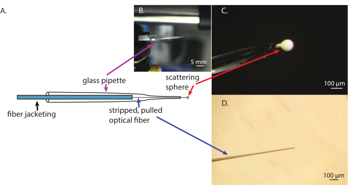
Figure 1: Stages of fabrication of the micro-optical intra-tissue radiometry probe. (A) A schematic of the optical probe. (B) A view of the finished optical probe. (C) A close-up of the scattering sphere attached to the pulled optical fiber inside the glass pipet support. (D) The pulled and cleaned optical fiber. Please click here to view a larger version of this figure.
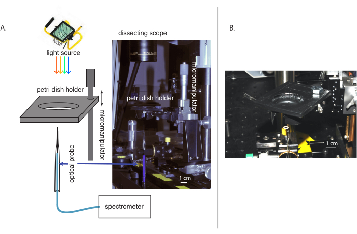
Figure 2: Images and diagrams of the experimental setup for measuring scalar irradiance inside the tissue. (A) An overall schematic and image of the experimental setup. (B) A close-up of the sample Petri dish holder. Please click here to view a larger version of this figure.
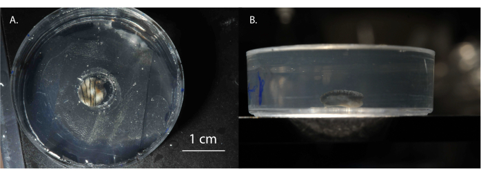
Figure 3: Clam tissue biopsy. (A) Top and (B) side views of a biopsy of clam tissue ready to be measured in the altered Petri dish filled with gelatin. Please click here to view a larger version of this figure.
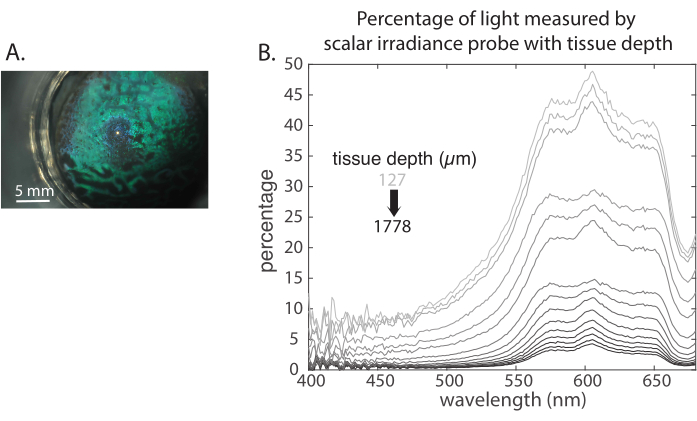
Figure 4: Representative data. (A) Microscope image of how the probe looks when coming up through the tissue. (B) Representative data obtained with the intra-tissue radiometry probe. Please click here to view a larger version of this figure.
Supplementary File 1: Matlab script used for loading and processing the data. Please click here to download this File.
Supplementary File 2: Matlab script used to generate the traces in Figure 4B. Please click here to download this File.
This protocol describes a technique for systematically characterizing the optical environment through a large volume of living tissue with a spatial resolution approximately on the scale of single cells. This inexpensive, flexible, and field-tractable method could be useful to any researchers studying the propagation of light within living systems. From experience, compared to existing methods7, these probes require a little more practice and skill to build but result in less tissue damage and the ability to more comprehensively characterize larger volumes of dense tissue.
This method comprises four parts. The first part, building the probe, was inspired by previous device designs10,11. The current approach was developed for systematic, less destructive scans of the entirety of thick tissue, as the pulled glass needle can gently slide between cells. It is also amenable for use in a field laboratory12,13,14. This protocol results in probes with ~20 µm diameter tips for measuring the downwelling radiance and an optional 50-100 µm diameter scattering sphere for measuring the scalar irradiance. Larger or smaller scalar irradiance spheres could be developed by modifying the materials used, for example, a UV-curable adhesive with a different initial viscosity. The weight in both the pipette pulling and the fiber process can be adjusted to result in more or less taper. The heating rate can also be modified through the distance from the torch flame to adjust the pulling process and the resulting taper.
The probe construction technique requires some manual skill and trial and error to perfect but can become reliable and quick with practice. Here, some troubleshooting nuances developed over time are presented. Pulling the optical fiber down from the jacketed end results in more consistent tapers. It is important to apply the opaquing pen before adding the spherical scattering tip, since the wetting properties of the opaque ink favorably influence the formation of a tidy ball of adhesive at the fiber tip. If the resulting adhesive ball is misshapen, it is possible to pull it off and try again. To do this, the micromanipulator can be used to slide the entire ball into the adhesive reservoir and then withdrawn very slowly. This usually pulls the first, misshapen attempt off, leaving it in the adhesive reservoir and making it possible to try again.
Treated with care, these probes can be used repeatedly for different samples. The biggest hazard is accidentally knocking the probe tip into something while moving it. Between measurements, they should be cleaned of cellular debris using isopropyl alcohol and compressed air. The probes can also be stored for weeks as long as the probe tip is not touching anything and there are no forces on the fiber optic assembly that may pull apart the tape and glue holding the probe inside the glass sleeve. This can be accomplished by clamping the fiber and glass pipette in several places to the edge of a high shelf.
The second and third parts of this method involve the mechano-optical aspects of the experiment and securing the tissue for measurement. This part of the method was developed specifically for measuring intra-tissue scalar irradiance inside giant clam tissue12. Here, details for troubleshooting these aspects of the method are presented. First, the biopsy should be large relative to the probe. This prevents the probe from moving the tissue as it transits. Additionally, the tissue should sit on the bottom of the Petri dish so that the elasticity and weight of the gelatin combine to keep the tissue in place during the measurement. It is also important that the room is cool enough to maintain the gelatin in an elastic, solid state under the experimental light source. Similarly, it helps to use an LED or other source with comparatively little heat generation relative to visible light.
The geometric and optomechanical parameters of the method are very flexible. For instance, the scalar irradiance probe was used to measure irradiance inside an intact mouse's brain and adipose tissue13,14. To do this, the probe was mounted on the manipulators on a standard rodent stereotactic frame, and the light source was mounted pointing toward the mouse's rostrum. In any geometry, the key to the successful use of this method is to always collect appropriate lamp and dark reference spectra at the start of any given measurement. If a probe breaks during a tissue measurement and there is no initial characterization without the tissue in place, the data will be difficult or impossible to interpret, and it will be necessary to start over with a fresh probe. In contrast, with appropriate references in place at the start, partial measurements are usable data.
The last part of this method concerns the data acquisition. The use of a fiber-optic spectrometer for monitoring signals from the probe is described, which ensures the ease of SMA coupling and provides fully spectral wavelength information. However, for systems with lower photon flux, it is also possible to couple these probes to photomultiplier tubes or avalanche photodiodes. In any case, all the detectors require reference measurements for each new measurement. Therefore, with only slight adjustments to the data collection methods described, all different types of optical parameters can be characterized.
Future interesting uses of this method could be the quantification of light deep within the bodies of larger mammals and within plants with complex radiative transfer properties, such as succulents.
The authors have nothing to disclose.
The authors thank Sanaz Vahidinia for introducing us to Dr. Jorgensen's colleagues and his work. This research was supported by grants from the Army Research Office (no. W911NF-10-0139), the Office of Naval Research (through MURI award no. N00014-09-1-1053), and NSF-INSPIRE award NSF-1343158.
1" travel ball bearing center+D11+A2:D31+A2:A2:D31 | Edmond Optics | 37-935 | Part 2 of manipulator for lowering sample |
1/4" thick acrylic sheet | McMaster-Carr | 8505K754 | For making Petri dish holder |
3/4" mini spring clamp | Anvil | 99693 | Use as weight for pulling optical fiber |
8 mm biopsy punch | Fisher Scientific | NC9324386 | For tissue sample |
Butane Torch | McMaster-Carr | MT-51 | Heat source for pulling fiber and pipette |
Collimating lens | Thorlabs | LLG5A1-A | To collimate light source through liquid light guide |
Compressed air | McMaster-Carr | 7437K35 | For drying pulled fiber and pipette |
Cyanoacrylate glue – liquid | McMaster-Carr | 66635A31 | For securing tapered fiber end at top of pulled pipette |
Electrical tape | McMaster-Carr | 76455A21 | For securing fiber in pipette and for adding grip to clamps |
Fine grade carborundum paper | McMaster-Carr | 4649A24 | Small triangle on exacto knife holder works well |
Gelatin | Knox | 10043000048679 | For securing the tissue biopsy in the petri dish |
Glass Pasteur Pipete | Fisher Scientific | 13-678-20B | Disposable glass pipette 5.75" in length |
Insulin syringes, 31G needle | BD | 320440 | For applying glue |
Isopropanol | McMaster-Carr | 54845T42 | For cleaning pulled fiber and pipette |
Kimwipe | Cole-Parmer | SKU 33670-04 | For wiping optical fiber and glass pipette clean |
LED driver | Thorlabs | LEDD1B | For powering the UV LEDs |
Light source for measurements | Cole-Parmer | UX-78905-05 | Low heat white light source for measurements |
Linear metric X-Y-Z axis rack and pinion stage | Edmond Optics | 55-023 | Part 1 of manipulator for lowering sample |
Liquid light guide | Thorlabs | LLG5-4T | For light source in measurements |
Magnetic feet | Siskiyou | MGB 8-32 | For use with magnetic strips |
Magnetic strips | Siskiyou | MS-6.0 | For mounting magnetically to breadboard |
Manipulator #1 | Siskiyou | MX10R | 4-axis manipulator with pipette holder |
Opaquer pen, small | WindowTint | TOP01 | For opaquing side of optical fiber to prevent stray light from enter probe |
Optical breadboard | Edmond Optics | 03-640 | For stable affixation of probe holder, sample, microscope and light source |
Optical fibers | Ocean Optics | P-100-2-UV-VIS | About 4 fibers are good to have |
Plasma light source | Thorlabs | HPLS345 | For tissue radiometry measurements |
Plastic plier clamp | McMaster-Carr | 5070A11 | Plier clamp used for weight in pulling pipette |
Polystyrene Petri dishes | Thomas scientific | 3488N10 | Sample holders, enough volume to hold sample thickness plus ~10 mm of gelatin on top |
Razor blades | McMaster-Carr | 3962A3 | For stripping jacketing from optical fiber |
Silicone oil lubricant | Thomas scientific | 1232E30 | For reducing friction between probe and tissue |
Software for analyzing data | Matlab | Chosen software for data analysis | |
Spectrometer + spectrometer software | Avantes | AvaSpec-2048L | Spectrometer can be any brand, this one is compatible with sma-terminated optical fibers and comes with its own software for running the spectrometer |
Titanium dioxide powder | Sigma Aldrich | 718467-100G | For making scattering sphere |
Toolour tabletop clip | Toolour | Toolour0004 | For holding pipette while pulling and for holding finished probes |
Trigger-action bar clamps | mcMaster-Carr | 51755A2 | Good for holding optical fibers while pulling or curing |
UV curable adhesive | Delo Photobond | GB368 | For making scattering sphere |
UV light source | Thorlabs | M365FP1 | Light source for curing adhesive in scattering ball, this one is sma-fiber compatible, higher intensity = less cure time |
White LED light source | Thorlabs | MCWHF2 | For characterizing pulled fiber and scattering sphere |