A Method to Estimate Cadaveric Femur Cortical Strains During Fracture Testing Using Digital Image Correlation
Summary
In this protocol, the femur surface strains are estimated during fracture testing using the digital image correlation technique. The novelty of the method involves application of a high-contrast stochastic speckle pattern on the femur surface, carefully specified illumination, high speed video capture, and digital image correlation analysis for strain calculations.
Abstract
This protocol describes the method using digital image correlation to estimate cortical strain from high speed video images of the cadaveric femoral surface obtained from mechanical testing. This optical method requires a texture of many contrasting fiduciary marks on a solid white background for accurate tracking of surface deformation as loading is applied to the specimen. Immediately prior to testing, the surface of interest in the camera view is painted with a water-based white primer and allowed to dry for several minutes. Then, a black paint is speckled carefully over the white background with special consideration for the even size and shape of the droplets. Illumination is carefully designed and set such that there is optimal contrast of these marks while minimizing reflections through the use of filters. Images were obtained through high speed video capture at up to 12,000 frames/s. The key images prior to and including the fracture event are extracted and deformations are estimated between successive frames in carefully sized interrogation windows over a specified region of interest. These deformations are then used to compute surface strain temporally during the fracture test. The strain data is very useful for identifying fracture initiation within the femur, and for eventual validation of proximal femur fracture strength models derived from Quantitative Computed Tomography-based Finite Element Analysis (QCT/FEA).
Introduction
Digital Image Correlation (DIC) is an image post-processing method that is used in the current protocol to estimate the full field surface strain of cadaveric femoral test specimens from time-sequence images obtained during mechanical fracture tests. The technique was first developed and applied in experimental stress analysis in the 1980's and has experienced a rapid increase in use in recent years1,2,3. It has several key advantages over more traditional approaches of mounting strain gauges on a structure including increased spatial distribution of the strain field, finer gauge lengths through increased camera resolution, and avoiding issues with strain gauge glue adhesion or compliance. A major advantage of DIC for biological tissues, such as bone, is that it can be applied to irregular geometries comprising of highly heterogeneous material properties4,5. Its primary drawback over traditional strain acquisition methods is that it requires expensive high speed video cameras of sufficient resolution for the measurement of the region of interest to achieve sufficient spatial and temporal sampling to accurately estimate strain fields.
The primary application of the temporal strain fields obtained from bone fracture DIC analysis is to validate the strain estimations in QCT/FEA models of femoral strength5. Such validation is the focus of many orthopedic research groups which predominantly utilize remote measurements of force and displacement from load cells and displacement transducers6,7,8. In addition, post-fracture image analysis of the fracture pattern has been combined with these remote measurements as further means of model validation9. More recently, the DIC method was applied to validate an FEA model of fracture and crack propagation in the proximal femur10. By utilizing strain correlation between models and experiments, even more confidence in the validity of computational models of proximal femora will be obtained and further advance the QCT/FEA diagnostic method closer to clinical use.
This work explains a detailed protocol to incorporate the necessary steps for DIC analysis in fracture testing of proximal femora. The procedure included the bone preparation steps of spraying a white paint on the bone surface and then speckling black spots on the dried white surface of the bone, methods of obtaining images with sufficient spatial and temporal resolution using high speed video cameras, and the process and tools we used for computing strain fields from these images. We also explained several caveats that may affect the quality of the measurements.
Protocol
All experiments were conducted with Institutional Review Board approval. The samples were obtained from anatomical research labs in collaboration.
1. Preparing Specimens for Testing
- Thaw the femora at RT for 24 h.
- When femur is in queue for testing, remove any wrap that was applied prior to freezing and wipe the femur with a dry towel to remove any remnant moisture, fatty deposits, or soft tissues. Pot the greater trochanter into a prefabricated aluminum cup with bone cement.
- Using a box to contain the particles as much as possible, spray the bone with white plastic primer to achieve a thin, uniform coating. Take care to cover the bone with one uniform layer of paint for optimal contrast and strong adhesion to the femur surface.
NOTE: The thickness was not measured. - Let the paint dry for at least 5 min. This is important to avoid the unintended mixing with speckled droplets in Section 2.
- Wrap the bone with wet cloth to avoid tissue dryness.
2. Speckling Process
- Approximately, add 1 part of water to 2 parts of paint for best speckling on the bone. Add water gradually (for a better mixture) to the acrylic paint to make a black color.
- Dip a clean toothbrush in a palette of black paint to absorb color and flick the brush to make black speckles over the white coating.
- Let the paint dry for 5 min before proceeding.
3. Image Acquisition
- Mount the prepared speckled femur in the mechanical test machine by inserting the potted distal end into the fixture and tighten two screws to secure the specimen.
- Adjust the two high intensity discharge light reflectors such that the femur surface achieves the highest illumination possible while avoiding reflections in the camera image. Proceed quickly with the following steps in Section 3 to avoid unwanted heating of the specimen from light radiation prior to the test.
- Reduce the aperture of the front and back view high speed video camera lenses such that the entire region of interest of the femur in the field of view is in focus.
- Readjust the light reflectors to further improve illumination while reducing glare.
- Set the image acquisition software to capture at 6000 frames/s at a resolution of 1024 x 512 pixels. Set the total number of frames to be acquired after the trigger signal is received to 12288. Arm high speed video software for image acquisition when the trigger signal is received from the test system. When the testing is complete, the video resides in the camera's buffer memory.
- Using the image acquisition software, save the video to disk by specifying a desired path and file name and clicking "Save". Be prepared to wait between 5 – 40 min for this process to complete depending on the number of frames to be saved.
4. Image Preparation
- Create separate working directories for front and back views of the femur.
- Use video analysis software to open the appropriate high speed video recording and note the key frame reference numbers at 1) the start of load frame actuator movement, and 2) the frame immediately after the fracture event.
- To downsample an uncompressed TIFF image sequence from the high speed video, open and run the "mov_frames.m" script in the working directory for the pertinent femur side.
- In the resulting dialog box, enter the ending frame number identified in Step 4.2 with a step size of 25 – 40. Click "Extract Frames" and inspect the working directory to ensure the *.tiff files were extracted correctly.
5. Finite Element Mesh Creation
- Use an external finite element meshing program to create the finite element mesh. Calculate 2D strains from the differential displacement vectors with the finite element method. Import the initial extracted *.tiff image into the finite element software pre-processor as a template for spline creation.
- Find two easy to identify fiduciary points in the image that are at opposite corners of the frame and record their X and Y coordinates (these will eventually be used in Step 6.1). These coordinates are arbitrary based on the convention the FEA software uses to import the *.tiff image. The coordinates of these points will be used to register the nodes of the finite element mesh with the corresponding pixels of the video images in Step 6.2.
- In an image editing software, open the same image that was imported into the finite element software preprocessor and record the X and Y direction values of the pixels associated with the points identified in step 5.2. These will eventually be used in Step 6.1.
- In the "Sketch" module of the finite element meshing program, use the spline tool to outline a closed section representing the region of interest. Verify the region is not too large such that the surface of the bone would move outside the region prior to fracture due to rotation.
- Prepare the closed section created in Step 5.4 for meshing by seeding the edges with a global mesh size of 1 mm under the menu "Seed Part Instance".
- Under "Assign mesh controls", set the element shape to quadrilateral.
- Mesh the closed section.
- Export the mesh to an ASCII file of the mesh database consisting of nodal coordinates and element definitions.
- With the resulting finite element input file open in a text editor, copy the node block containing node numbers and coordinates into a new text file and save as "nodes.txt". Repeat for the element block and save the new text file as "elements.txt".
6. Register the FE Mesh with the High Speed Video Images and Conduct Digital Image Correlation Analysis
- Inside a new session, create 2-element row vectors called ab1 and ab2 with the values identified in Step 5.2., and px1 and px2 with the values identified in Steps 5.3 by typing those vector names on the command line. Save the Workspace as "points.mat".
- Run the script "convert_imagesize.m" to register the points from the finite element mesh with the extracted high speed video image.
- Run the script "rrImageTrackGui.m". Load the first image ("p01.tif") and enter the number of the last *.tiff file that was extracted as the total number of images to process.
- Load the mesh created in Step 5.7 by making sure the mesh option is set to "Read from file" and click "Accept". The finite element mesh should appear over the bone image.
- Specify the tracking values based on the following guidelines for Tracking parameters and click "Proceed" (keeping in mind that the parameter values are image size, texture and amount of deformation taking place, and need to be tested carefully on a case-by-case basis).
- Use a starting Kernel size of 21. The Kernel size, n, is the size of an n x n window (where n is an odd number) of pixels that is used for the cross-correlation and determination of the deformation vector for that area that will be used for strain calculations.
- Use a starting Subpixel size of 4. The Subpixel size, m, is the size of the (2m+1) x (2m+1) sub-window over which subpixel deformation is computed by assuming homogeneous strain in that sub-window.
- Use a starting Smoothness factor of 2. Smoothness factor is the amount of smoothing applied to the displacement field at tracked locations before computing strains.
- Use a starting maxMove factor of 10. maxMove factor is the maximum number of pixels that any node can be away from its trajectory relative to its neighbor's trajectory. This helps avoid badly tracking to deformation.
- Use a starting smoothGrid factor of 15. The smoothGrid factor is the size of the grid (slightly coarser than the mesh of the tracked nodes) that is used for the smoothing.
- Select a guide point that has significant contrast around it while avoiding areas with any glare or blurriness. Check this point by clicking "Check guide" and verify the correlation peak is strong (at least twice the amplitude) compared to its neighbors. Click "Accept" and "Perform Tracking" when satisfied. This can be a lengthy computational process where differential displacement is computed for the temporal image sequence.
- After Step 6.6 has completed, click "Animate". When animate has finished, click "Write strains (post processing software)", enter *.exe, and then select writeStrainRR_simple.exe11. This will calculate the strains. Close the GUI.
7. Post-processing of Displacement and Strain Data
- To obtain strain Vs. frame number, run "analyzeFailurePrecursor.m" from the command line with an input argument of step size (choose 20 – 30). The peaks will signify bone damage, and the largest peak will correspond to the frame close to global bone failure.
- To create movie files of the strains, run "makeMovies.m" from the command window with the arguments (numVars, endstep, flag).
NOTE: The argument numVars is defined as 1 – 3 being displacements, 4 – 6 being xx, yy, and xy strain components, 7 & 8 are the two principal and von Mises strain, and 9 is the strain energy. The argument endstop is the last frame to be included in the movie.- Set the optional argument flag to 1 to only create movies for the entity specified for the numVars argument and to 0 to create movies of all variables.
8. Fine Tuning and Refinement of Results
- If DIC tracking gave poor results such as a discontinuous strain field that falls outside continuum mechanics assumptions, determine what is happening and why the tracking is failing. Repeat Section 6 paying particular attention to the adjustment of tracking parameters. A secondary option may be to return to the finite element software and create a more uniform and possibly finer mesh.
- If DIC tracking gave reasonable results, create a finer series of images for DIC. Using those key frame reference numbers from Step 4.2 and the corresponding frame rate of the video, identify the frame spacing for three different regimes of interest in the fracture test with the requirement in mind that the points should be moving no more than 6 pixels between frames.
NOTE: For the initial segment of the test when the strains are building up slowly in the femur, the frame spacing will be relatively large (for example, for the 100 mm/s displacement rate, the frame spacing for this portion is 3333 μs). For the intermediate portion of the test closer to the fracture frame, strain is increasing more rapidly and smaller frame spacing is needed (1667 μs for the 100 mm/s displacement rate). For the final portion right before fracture, the frame spacing is at its smallest (16.7 μs at the 100 mm/s displacement rate). - Optional for documentation purposes only: Using the information from Step 8.2, create formatted data entries in an ASCII file entitled "steps.txt" containing a row of data for each frame spacing. The format of each row will be the starting frame of that regime separated by the number of frames to skip (based on Step 8.2) separated by a colon then the final frame of that regime (i.e. a format of "1:20:200" would instruct the extraction software to extract frame 1 to frame 200 in steps of 20).
- Immediately following that designation, insert a tab and designate the image extraction number range (for the "1:20:200" example, the complete row designation would be "1:20:200 <Press TAB>1:11" without the quotations). Repeat for the other two test regimes so there will be three rows of information in the "steps.txt" file. This file serves as a record for how the images were extracted from the original high speed video.
- Run the mov_Frames.m code again this time specifying multiple frame spacing regimes in the dialog box. Enter the frame numbers and step sizes identified in Step 8.2 to determine the start, finish, and frame skip parameters expected in the tool's dialog box. Make sure to do this in a new directory otherwise the original images will be overwritten.
- Repeat Sections 6 and 7 and review the results for improvement. Each femur may require different additional iterations depending on the nature of the fracture event, speckle pattern, and lighting. When repeating Step 6.5, keep the settings the same except reduce maxMove to 6 (from 10).
Representative Results
Before the speckling process, the femur is cleaned from excess fat and soft tissues, and the greater trochanter is potted in an aluminum cup. During solidification of polymethylmethacrylate (PMMA), the bone is wrapped in a saline soaked cloth to avoid tissue dryness. Once PMMA is solidified, the bone is cleaned again right before spraying (Figure 1). Then, the bone surface is sprayed or brushed with a water-based plastic white color. Once dried, the white surface is speckled with black color to have a stochastic pattern of black spots on the white background (Figure 2). Once the bone is placed in the testing fixture, the lights and high-speed video cameras are set, and the optimal contrast of the pattern and the focus of the cameras are checked prior to testing (Figure 3). The DIC method requires a high contrast speckling pattern and sufficient illumination. Otherwise, the results may be affected by several issues such as oversaturation of the surface, poor contrast, and dull images (Figure 4). Uncompressed images from the high speed videos are able to be extracted in multiple temporal sampling regimes and the DIC tracking algorithm can be operated through graphical user interfaces (Figure 5). The outline of the femur sample is used to identify the region of interest for strain field estimation (Figure 6A) and for creation of a finite element mesh for strain calculation (Figure 6B). The onset of fracture is detected by monitoring the degree of strain deviation during testing, with peaks representing bone damage and time frame of fracture (Figure 6C). Finally, 2D strain fields are superimposed back onto the untested bone image for enhanced visualization (Figure 6D).
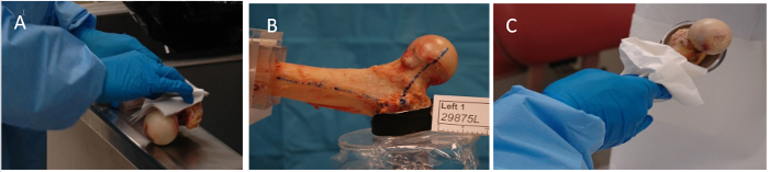
Figure 1: Bone Preparation before Painting the Bones. (A) cleaning the bone from fat and moisture after being thawed; (B) potting greater trochanter; (C) cleaning before spraying process Please click here to view a larger version of this figure.
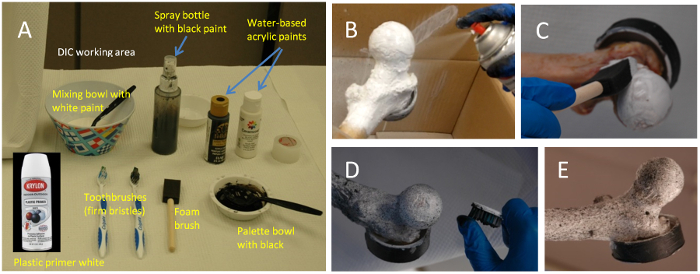
Figure 2: Painting Process. (A) DIC working area and necessary tools; (B) spraying bone with white primer; (C) brushing white color on the bone surface; (D) speckling black spots on the white bone surface; (E) final speckled surface of the bone ready for testing Please click here to view a larger version of this figure.
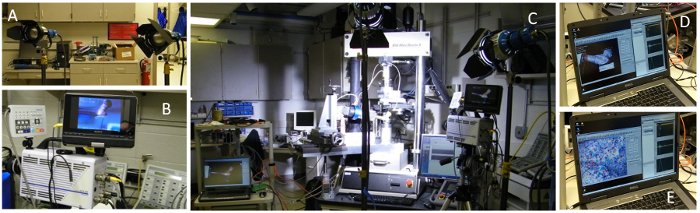
Figure 3: Lighting and Camera Settings. (A) setting up lamps and shields; (B) setting up high speed video cameras; (C) a bone sample loaded to the testing machine with lights and cameras ready for check and test; (D) checking the images for the functionality of the cameras; (E) examining the area of interest, in the femoral neck, for focusing zones, depth of field, lack of blur, and general quality of images for DIC Please click here to view a larger version of this figure.
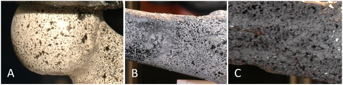
Figure 4: Bone DIC Caveats. (A) oversaturation on the head region; (B) mixing and flowing of black and white when white surface is not dry; (C) poor contrast, local oversaturation, poor clarity of the image Please click here to view a larger version of this figure.
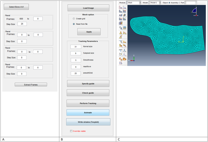
Figure 5: Custom Scripting Dialogs that were used in the DIC Processing. (A) mov_frames.m, (B) rrImageTrackGui.m, (C) generated 2D mesh Please click here to view a larger version of this figure.
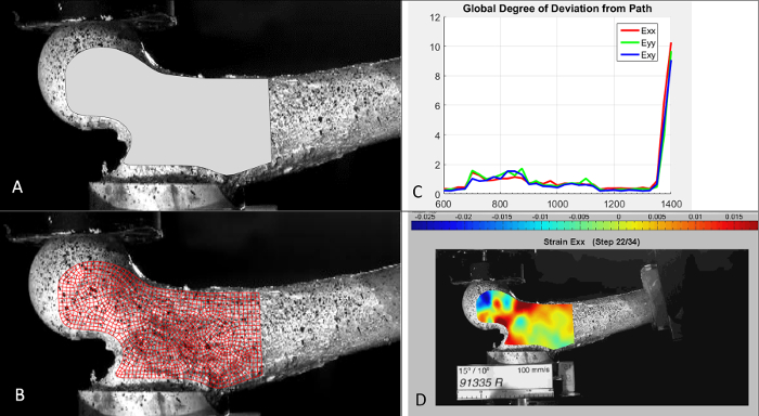
Figure 6: Example of Intermediate DIC Results. (A) spline drawn to highlight the region of interest, (B) generated mesh overlaid on bone image, (C) strain deviations as a function of high speed video frame, (D) calculated strain contour plot associated with the 2 test images prior to bone fracture Please click here to view a larger version of this figure.
Discussion
We introduced a protocol to consistently prepare femoral samples for high contrast imaging during fracture testing which were then used to estimate full field strain distributions with DIC. This protocol ensured appropriate contrast texture of black tracking speckles against a solid white background on the bone surface. Following this protocol, we successfully replicated the estimation of strains using DIC analysis for eighty-nine femora.
DIC is an optical method which involves placing a mesh over a series of images captured by high speed video cameras and tracking the pixel intensity changes between frames using a cross-correlation algorithm. During the experiments, we found several considerations that need to be taken into account for the accuracy and robustness of the method and those details are reflected in the presented protocol in detail. First, we found the sensitivity and the resolution of cameras are of great importance for the spatial strain measurements of interest. Second, a very fine texture of contrasting black marks on white surface should be avoided as they may not be visible to the cameras. Third, cameras and lighting should be set at appropriate distances to ensure optimal aperture size for depth of field and the quality and contrast of the images. Excessive lighting may lead to saturation of the images resulting in poor contrast. Finally, the temporal spacing between images needs to be set such that the surface speckles do not move more than 6 pixels between frames so that tracking is accurately captured during cross-correlation.
As demonstrated in this work, DIC has the capability to provide full field time-sequence strain estimates for femur fracture tests, something not easily obtained with strain gauge experimental techniques. Although strain gauge measurements have been employed by a number of researchers, such measurements can be hindered by inadequate mounting adhesion to the bone surface, gauge conditioning, and a limited spatial distribution12,13. In contrast, full-field strain data is extremely useful for validation of QCT/FEA models of bone strength by comparing strain fields between model and test, and it also has clinical application to correlate femoral fracture types with the pattern of strain development on the surface of the femur for this physiological fall load case5,9. While fixture compliance could be a problem when testing very stiff femora, DIC circumvents this issue by calculating cortex strains directly from bone local deformation thus, eliminating fixture compliance as a source of errors when estimating femoral stiffness. The results from these image correlations may aid in developing better QCT/FEA models including material failure and metrics of damage and fracture. These can eventually help guide therapy decisions especially for osteoporotic patients.
The method does have several drawbacks, however. The bone specimen surface must be uniformly covered with a stochastic speckle pattern which has high contrast with the background. Occasionally reflections from lighting or large deformations can alter the ability for the algorithm to track the pattern precisely from frame to frame (Figure 4). A second limitation is when single camera (2D) DIC is employed, strain calculations can be affected where the bone surface plane deviates from being parallel with the camera image sensor plane14. This can occur when the femoral surfaces rotate towards or away from the camera during fracture testing. We are exploring future work in this area to add a second camera and utilize 3D DIC methods for improved accuracy. Until recently, such methods have been out of reach in a research setting but are now becoming more readily available. Another limitation of the method specific to biological tissue is the uncertainty of paint adhesion to the femur surface. By our observations, this was not an issue in our testing, but any slippage of the femur tissue and paint would affect the results. Additionally, any non-bone tissue left behind during bone preparation can interfere with cortex strain measurements. Finally, the image tracking settings and mesh density are factors that may affect the quality of results from the DIC analysis and need to be carefully considered.
The current protocol presents a method to efficiently and consistently prepare femoral specimens for digital image correlation analysis and for estimation of corresponding strain fields from high speed camera imaging during fracture testing. It has been demonstrated in our laboratory to yield consistency over multiple testing timeframes and with varying research personnel and operators over a 6 year time period. The procedure for DIC presented here for femoral preparation and testing can be easily extended to other bone types.
Declarações
The authors have nothing to disclose.
Acknowledgements
The authors would like to thank the Materials and Structural Testing Core at Mayo Clinic for their technical support in performing the fracture testing. In addition we would like to thank Ramesh Raghupathy and Ian Gerstel for their assistance in developing the DIC scripts and specific details of the DIC protocol during their tenure at Mayo Clinic, and the Victor Barocas Research Group, University of Minnesota for the underlying open source software that performs the core of the digital image correlation strain calculations11. This study was financially supported by the Grainger Innovation Fund from the Grainger Foundation.
Materials
| Krylon plastic primer white | Krylon, Peoria, AZ, USA | N/A | Used as a base coat for a smooth white finish on bone surface |
| Water-based acrylic white and black paint | Plaid Enterprises (Ceramcoat), Norcross, GA, USA | N/A | Paint source for white and black colors |
| Mixing bowl | Not specific (generic) | N/A | Used to mix and prepare paint |
| Foam brush | Linzer Products, Wyandanch, NY, USA | N/A | Used to apply paint on bone surface |
| Toothbrush | Colgate-Palmolive, New York, NY, USA | Firm bristle | Used to apply appropriate size and distribution of speckling pattern |
| Hygenic Orthodontic Resin (PMMA) | Patterson Dental, St Paul, MN, USA | H02252 | Controlled substance and can be purchased with proper approval |
| Kenmore Freezer | Sears Holdings, Hoffman Estates, IL, USA | N/A | Used to maintain a -20oC storage enviroment for bone specimens |
| Physiologic Saline (0.9% Sodium Chloride) | Baxter Healthcare, Deerfield, IL, USA | NDC 0338-0048-04 | Used for keeping specimens hydrated |
| Scalpels and scrapers | Aspen Surgical (Bard-Parker), Caledonia, MI, USA | N/A | Used to remove soft tissue from bone specimens |
| Fume Hood | Hamilton Laboratory Solutions, Manitowoc, WI, USA | 70532 | Used for ventilation when preparing PMMA for potting of specimens |
| Lighting units | ARRI, Munich, Germany | N/A | Needed for illumination of target for image capture |
| High-speed video camera | Photron Inc., San Diego, CA, USA | Photron Fastcam APX-RS | Used to capture the high speed video recordings of the fracture events |
| Photron FASTCAM Imager and Viewer | Photron Inc., San Diego, CA, USA | Ver.3392(x64) | Used to record and view the high speed video recordings |
| Camera lens | Zeiss, Oberkochen, Germany | Zeiss Planar L4/50 ZF Lens | Needed for appropriate image resolution |
| ABAQUS CAE | Dassault Systemès, Waltham, MA, USA | Versions 6.13-4 | Used for defining region of interest and creating finite element mesh |
| MATLAB | Mathworks, Natick, MA, USA | Version 2015b | Used for image processing and DIC analysis |
| TecPlot | TecPlot Inc., Bellevue, WA | Used for post processing of strain fields | |
| Strain Calculator Software | Victor Barocas Research Group, University of Minnesota, Minneapolis, MN, USA | http://license.umn.edu/technologies/20130022_robust-image-correlation-based-strain-calculator-for-tissue-systems | Used to calculate strain field |
| mov_frames.m | Matlab script, Mayo Clinic, Rochester, MN,USA | N/A | Used to downsample uncompressed images from high speed video files |
| convert_imagesize.m | Matlab script, Mayo Clinic, Rochester, MN,USA | N/A | Used to register image pixel coordinates with mesh coordinates |
| rrImageTrackGui.m | Matlab script, Mayo Clinic, Rochester, MN,USA | N/A | Used to perform the image cross-correlation to obtain deformations and run Strain Calculator |
| analyzeFailurePrecursor.m | Matlab script, Mayo Clinic, Rochester, MN,USA | N/A | Used to track the peak strain components temporally |
| makeMovies.m | Matlab script, Mayo Clinic, Rochester, MN,USA | N/A | Used to create portable *.avi movies of the deformation components, strain components, principal strains, von Mises strain, and strain energy |
Referências
- Peters, W., Ranson, W. Digital imaging techniques in experimental stress analysis. Opt Eng. 21 (3), 213427-213427 (1982).
- Kwon, O., Hanna, R. The Enhanced Digital Image Correlation Technique for Feature Tracking During Drying of Wood. Strain. 46 (6), 566-580 (2010).
- Sutton, M. A., Orteu, J. J., Schreier, H. W. Image Correlation for Shape, Motion and Deformation Measurements. Adv of Opt Methods in Exp Mech. 3, (2009).
- Grassi, L., et al. How accurately can subject-specific finite element models predict strains and strength of human femora? Investigation using full-field measurements. J Biomech. 49 (5), 802-806 (2016).
- Den Buijs, J. O., Dragomir-Daescu, D. Validated finite element models of the proximal femur using two-dimensional projected geometry and bone density. Comput Methods Programs Biomed. 104 (2), 168-174 (2011).
- Keyak, J. H., Rossi, S. A., Jones, K. A., Skinner, H. B. Prediction of femoral fracture load using automated finite element modeling. J Biomech. 31 (2), 125-133 (1998).
- Lotz, J. C., Cheal, E. J., Hayes, W. C. Fracture Prediction for the Proximal Femur Using Finite-Element Models . 1Linear-Analysis. J Biomech Eng-T Asme. 113 (4), 353-360 (1991).
- Cody, D. D., et al. Femoral strength is better predicted by finite element models than QCT and DXA. J Biomech. 32 (10), 1013-1020 (1999).
- Dragomir-Daescu, D., et al. Robust QCT/FEA models of proximal femur stiffness and fracture load during a sideways fall on the hip. Ann Biomed Eng. 39 (2), 742-755 (2011).
- Bettamer, A., Hambli, R., Allaoui, S., Almhdie-Imjabber, A. Using visual image measurements to validate a novel finite element model of crack propagation and fracture patterns of proximal femur. Comput Methods Biomech Biomed Eng Imaging Vis. , 1-12 (2015).
- Raghupathy, R., Barocas, V. . Robust Image Correlation Based Strain Calculator for Tissue Systems. , (2016).
- Taddei, F., et al. Subject-specific finite element models of long bones: An in vitro evaluation of the overall accuracy. J Biomech. 39 (13), 2457-2467 (2006).
- Grassi, L., et al. Accuracy of finite element predictions in sideways load configurations for the proximal human femur. J Biomech. 45 (2), 394-399 (2012).
- Gerstel, I., Raghupathy, R., Dragomir-Daescu, D. Digital Image Correlation Identifies Quantitative Characteristics in Proximal Femur Fracture Crack. ORS Annual Mtg. , (2012).
