This work presents a detailed surgical planning protocol using 3D technology with free open-source software. This protocol can be used to correctly quantify femoral anteversion and simulate derotational proximal femoral osteotomy for the treatment of anterior knee pain.
Anterior knee pain (AKP) is a common pathology among adolescents and adults. Increased femoral anteversion (FAV) has many clinical manifestations, including AKP. There is growing evidence that increased FAV plays a major role in the genesis of AKP. Furthermore, this same evidence suggests that derotational femoral osteotomy is beneficial for these patients, as good clinical results have been reported. However, this type of surgery is not widely used among orthopedic surgeons.
The first step in attracting orthopedic surgeons to the field of rotational osteotomy is to give them a methodology that simplifies preoperative surgical planning and allows for the previsualization of the results of surgical interventions on computers. To that end, our working group uses 3D technology. The imaging dataset used for surgical planning is based on a CT scan of the patient. This 3D method is open access (OA), meaning it is accessible to any orthopedic surgeon at no economic cost. Furthermore, it not only allows for the quantification of femoral torsion but also for carrying out virtual surgical planning. Interestingly, this 3D technology shows that the magnitude of the intertrochanteric rotational femoral osteotomy does not present a 1:1 relationship with the correction of the deformity. Additionally, this technology allows for the adjustment of the osteotomy so that the relationship between the magnitude of the osteotomy and the correction of the deformity is 1:1. This paper outlines this 3D protocol.
Anterior knee pain (AKP) is a common clinical issue among adolescents and young adults. There is a growing body of evidence that increased femoral anteversion (FAV) plays an important role in the genesis of AKP1,2,3,4,5,6,7,8,9,10,11. In addition, this same evidence suggests that a derotational femoral osteotomy is beneficial for these patients, as good clinical results have been reported1,2,3,4,5,6,7,8,9,10,11. However, this type of surgery is not widely used in daily clinical practice among orthopedic surgeons, especially in the cases of adolescents and young active patients with anterior knee pain27, because the many controversial aspects generate uncertainty. For example, it has been observed that sometimes the correction obtained after the osteotomy is not what was previously planned. That is, there is not always a 1:1 ratio between the amount of rotation planned when performing the osteotomy and the amount of FAV corrected. This finding has not been studied to date. Therefore, it is the subject of the present paper. To explain the discrepancy between the magnitude of the rotation performed with the osteotomy and the magnitude of the correction of FAV, it was hypothesized that the axis of rotation of the osteotomy and the axis of rotation of the femur may not coincide.
One of the main problems to be addressed is accurately locating the femoral axis of rotation and the axis of rotation of the osteotomy. The first femoral axis is the femoral axis measured on the CT scan at the time of the patient's diagnosis, while the second femoral axis is the femoral axis measured after performing the osteotomy. Over the last decade, 3D technology has become increasingly important in preoperative planning, especially in orthopedic surgery and traumatology, for simplifying and optimizing surgical techniques15,16. The development of 3D technology has supported the creation of anatomical biomodels based on 3D imaging tests such as CT, in which customized prosthetic implants can be adapted17,18,19 and osteosynthesis plates can be molded in the case of fractures20,21,22. Additionally, 3D planning has already been used in previous studies to analyze the origin of the deformity in unilateral torsional alterations of the femur14. Currently, there are several software programs that are completely free and adaptable to most computers and 3D printers on the market, making this technology easily accessible to most surgeons in the world. This 3D planning allows for the accurate calculation of the initial axis of rotation of the femur and the axis of rotation of the femur after the intertrochanteric osteotomy has been performed. The main purpose of this study is to demonstrate that the axis of rotation of the femoral intertrochanteric osteotomy and the axis of rotation of the femur do not coincide. This 3D technology makes it possible to visualize this discrepancy between the axes and correct it through an adjustment of the osteotomy. The ultimate goal is to stimulate greater interest from orthopedic surgeons in this type of surgery.
This protocol with a 3D methodology is conducted in four fundamental steps. First, CT images are downloaded, and the 3D biomodel is created from the DICOM (Digital Imaging and Communication in Medicine) files of the CT scan. Higher-quality CT scans allow for better biomodels but mean the patient receives more ionizing radiation. For surgical planning with biomodels, the quality of conventional CT is sufficient. The DICOM image of a CT scan consists of a folder with many different files, with one file for each CT cut made. Each of these files contains not only the CT cut's graphical information but also the metadata (data associated with the image). To open the image, it is essential to have a folder with all the files of the series (the CT). The biomodel is extracted from the totality of the files.
Second, to obtain the 3D biomodel, it is necessary to download the 3D Slicer computer program, an open-source program with many utilities. Furthermore, this is the most widely used computer software in international 3D laboratories and has the advantage of being completely free of cost and downloadable from its main page. As this software is an X-ray image viewer, the DICOM image must be imported into the program.
Third, the first biomodel obtained with 3D Slicer will not match with the definitive one, because there will be regions such as the CT table or bones and soft parts nearby that are of no interest. The biomodel is "cleaned" almost automatically with the 3D design software, MeshMixer, which can also be downloaded directly from its official website for free. Finally, femoral anteversion is calculated, and the osteotomy is simulated using another free software from the Windows Store, 3D Builder.
The study was approved by the ethics committee of our institution (reference 2020-277-1). Patients signed the CT scan informed consent.
1. Downloading the CT images
2. Obtaining the 3D biomodel (Supplementary File 1-Figure S1)
3. Preparation of the biomodel
4. Calculation of the proximal femoral anteversion
Femoral anteversion can be measured by different methods. Some of them focus on the femoral neck, using the line passing through the center of the neck and one passing through the femoral condyles as references. Others add a third reference point at the lesser trochanter23. Murphy's method, which is the most reliable in clinical practice because it has the best clinical-radiological relationship, is one such method using a third reference point25,26. In addition, the torsional component of the femur, which varies in the different segments of the bone, contributes to the calculation of the FAV24.
In a preliminary study, the FAV was measured in 10 3D biomodels using Murphy's method 12. Then, a 10°, 20°, and 30° intertrochanteric rotational femoral osteotomy was simulated on each of the 3D biomodels (Group I). Once the osteotomy was performed, the FAV was remeasured, and it was observed that the rotation axis of the femur did not coincide with the rotation axis of the osteotomy in group I.
Through the 3D guides, one can see that the two axes do not coincide because the red guide does not match the violet guide (3D Builder, Supplementary File 1). The red guide represents the rotational axis of the osteotomy, while the violet guide represents the rotational axis of the femur. For this reason, it is necessary to make an adjustment that involves realigning the two guides so that the rotation axis of the femur and the rotation axis of the osteotomy coincide (3D Builder, steps 4.8.1-4.8.3, Supplementary File 1) (Figure 1).
Therefore, another surgical simulation of the osteotomy was performed, and a reset was needed to match the axis of femoral rotation with the rotation axis of the osteotomy. The resulting FAV was measured again (Group II). Table 1 details the values of the FAV obtained in each group for the three magnitudes of rotational osteotomy (10°, 20°, and 30°). The variable"correction" was defined as the difference between the initial FAV and the FAV measured after the osteotomy. When the adjustment was made so that the femur's rotation axis and the osteotomy's rotation axis coincided, the relationship between the planned correctionand the final correction was 1:1 in the three correction magnitudes(10°, 20°, and 30°) (Table 2). The same did not occur in group 1, inwhich the 1:1 ratio was not achieved (Table 2).
Group 1 | Group 2 | P value | |
FAV 10° | 22° (±9.1º) | 17.9° (±8.8º) | <0.001 |
FAV 20° | 15.8° (±8.7º) | 7.7° (±9.6º) | <0.001 |
FAV 30° | 8.9° (±8.9º) | -2.2° (±10.3º) | <0.001 |
Table 1: FAV comparison between Group 1 and Group 2. The means and SD values are presented. Abbreviation: FAV = femoral anteversion.
Derotation (correction) | Group 1 | Group 2 | P value |
10° | 6.9° (±1.4º) | 11.1° (±2.8º) | <0.001 |
20° | 13.1° (±3.2º) | 21.3° (±6.0º) | <0.001 |
30° | 20° (±5.1º) | 31.3° (±8.3º) | <0.001 |
Table 2: Correction comparison between group 1 and group 2. The means and SD values are presented.
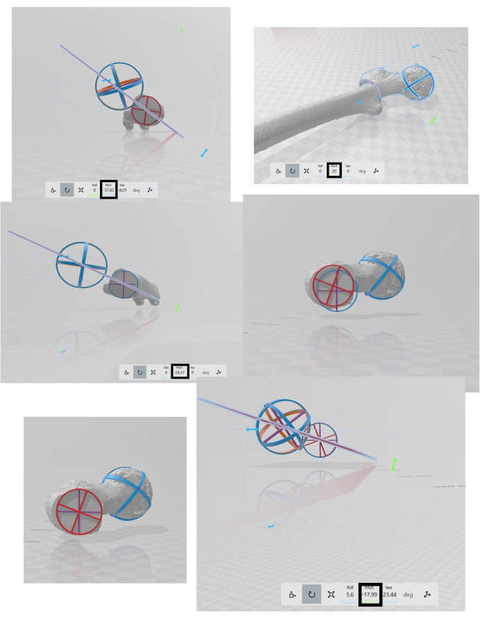
Figure 1: The final outcome: The result of the osteotomy after the adjustment has been applied. There are six panels, which should be read from left to right and from top to bottom. First panel: femoral anteversion calculated in the CT using Murphy's method. Second panel: Rotational osteotomy of the proximal femur (internal rotation of 20°). Third panel: New femoral anteversion after the rotational osteotomy of the proximal femur (the final correction does not coincide with the planned correction). Fourth panel: The guides do not match. Fifth panel: Matching the guides. Sixth panel: New femoral anteversion with the adjustment made (the final correction coincides with the planned correction). Please click here to view a larger version of this figure.
Supplementary File 1: Software instructions. The 3D Slicer software (obtaining and creating the biomodel); the MeshMixer software (making the solid model); the 3D Builder software (importing the biomodel, performing the femoral osteotomy, and calculating the femoral anteversion). Please click here to download this File.
Supplementary File 2: Osteotomy guides. A 3mf file containing the red circular guide, purple circular guide, sphere, and red plane (https://www.dropbox.com/work/JoVE%20Review/File%20requests/64474?preview=Guides+osteotomy+Caterina+Chiappe.3mf).
The most important finding of this study is that 3D technology allows the planning of proximal external derotational femoral osteotomy. This technology can simulate the surgery that is to be performed on a specific patient on the computer. It is a simple, reproducible, and free technique that uses software adaptable to most computers. The only technical problem may be that the 3D builder software works only with the Windows operating system. The major limitation is the learning curve. This protocol is still in the preliminary study phase and can certainly be improved in the future, but it is already an available resource that can help surgeons with decision-making. The technology also heightens the precision of the surgery. In addition, 3D technology can increase surgeons' adherence to this surgical technique. It is also important considering that there are currently no other preoperative planning methods for derotational femoral osteotomy.
The critical procedures during the 3D surgical planning can be summarized in three steps. First, it is important to obtain a good, clean 3D biomodel where only the anatomical part useful for planning is selected. For this, it is necessary to be as accurate as possible during protocol steps 3.3-3.3.2. Second, the intertrochanteric osteotomy must be performed correctly, making sure that the femur is parallel to the x-axis and perpendicular to the y-axis. These axes are already drawn in the work plan of the 3D builder software (protocol steps 4.4.1-4.4.1.3). Third, the femoral anteversion must be calculated correctly in the first measurement and after the osteotomy. For this purpose, the provided guides should be positioned properly. This is done by making sure that the circumferential guides (violet and red) and the sphere are in contact with three points of the cortex of the bone and that the red plane passes exactly through the center of the sphere and the center of the circumferential guides (protocol steps 4.5.1-4.5.9).
The differences observed between group I and group II can be explained as follows. There was no concordance between the femoral rotation axis and the rotation axisof the osteotomy. When both axes coincided in 3D planning, which is called "adjustment", the relationship between the planned correction and the final correction obtained did coincide. Thus, this 3D technology provides a reliable evaluation of both axes. In this study, there were differences of up to 10° between what was intended to be corrected and what was actually corrected. These degrees of differences could be disastrous for the knee because patellofemoral pressures will significantly worsen13, and the patient's pain, which is the cause of the consultation, will not be resolved. In addition, 3D technology makes it possible to have the printed femur in the operating room with the osteotomy performed and with the appropriate "adjustment" so that the rotation axis of the femur coincides with the rotation axis of the osteotomy.
The main limitation of this study is the absence of an evaluation ofintra-observer and interobserver variability, which would provide more consistency to the results. In summary, the use of 3D technology for the surgical planning of proximal femoral derotational osteotomy allows the precision of this surgical technique to be improved and provides more certainty to orthopedic surgeons, making this surgery more attractive for them.
The authors have nothing to disclose.
The authors have no acknowledgments.
3D Builder | Microsoft Corporation, Washington, USA | open-source program; https://apps.microsoft.com/store/detail/3d-builder/9WZDNCRFJ3T6?hl=en-us&gl=us | |
3D Slicer | 3D Slicer Harvard Medical School, Massachusetts, USA | open-source program; https://download.slicer.org | |
MeshMixer | Autodesk Inc | open-source program; https://meshmixer.com/download.html |