אפיון מנוע אינדוקציה AC
English
COMPARTILHAR
Visão Geral
מקור: עלי באזי, המחלקה להנדסת חשמל, אוניברסיטת קונטיקט, סטורים, CT.
מטרות הניסוי הן למצוא את הפרמטרים המעגליים המקבילים של מנוע אינדוקציה תלת פאזי באמצעות המעגל המקביל לכל שלב ובדיקות דומות לאלה המשמשות באפיון שנאי. בהנדסת חשמל, ניתן לקבוע מעגל שווה ערך (או מעגל תיאורטי) עבור מערכת נתונה. המעגל המקביל שומר על כל המאפיינים של המערכת המקורית, ומשמש כמודל כדי לפשט את החישובים. מטרה נוספת היא להפעיל את המנוע באזור מהירות המומנט הליניארי.
Princípios
Procedimento
Resultados
A common mistake in finding the equivalent circuit parameters of induction machines is to use the three-phase measured power in calculations of the per-phase equivalent circuit, while one third of the power should be used: three phases consume the measured power, and thus, one third of the power is in one phase.
Calculations of the equivalent circuit parameters are similar to those of the transformers, but it is common to split X1 and X2' per the NEMA frame of the machine. For example, if the motor is of NEMA frame A or D, then X1 and X2' are assumed to be equal, while if the motor is of NEMA frame B, then X1 and X2' are split as 40% and 60% of Xeq, respectively, and if the motor is of NEMA frame C, then X1 and X2' are split as 30% and 70% of Xeq, respectively. It is expected to find that X1 and X2' are 1-10% of Xm, R1 and R2' are on the order of mΩ to several Ω depending on the motor power rating, and RC would be on the order of tens to hundreds of Ω, as it is several orders of magnitude larger than R1 and R2'.
The linear region of the induction motor torque-speed curve is found using the load test and can be extrapolated from no-load to full- or rate-load conditions. A typical torque-speed curve is shown in Fig. 3 for several NEMA frames and the linear region is the right-most region close to the 90-100% speed.
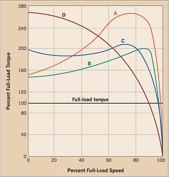
Figure 3: Typical torque-speed curves for various NEMA frames.
Applications and Summary
Three-phase induction machines, especially induction motors, are the workhorses of modern industry. Appropriately characterizing an induction motor provides engineers and technicians with information on the motor’s efficiency and torque-speed characteristics. These are essential in determining which motor size and frame best fits an application. Once a motor is characterized and the torque-speed curve is known from equivalent circuit parameters using the tests described, different NEMA frames have different curve shapes. For example, an elevator application requires high-starting torque; therefore, frames, such as NEMA frame D, are more suitable than A or B. When dealing with the induction motor’s integral parts of larger systems that consume considerable amounts of energy (e.g., chillers), knowing the equivalent circuit parameters of a motor can provide good estimates of the motor’s efficiency and its contribution to energy consumption in that larger system.
Transcrição
AC Induction Motors are the workhorses of modern industry, as they are simple, rugged, and reliable. An induction motor has only two main parts. The first is the stationary part called the stator, which consists of stationary coils around a cavity. Suspended in the cavity is the rotor, which is a pair of end rings capping a cylindrical arrangement of bars. This is often called the squirrel cage. The electrical parameters of these two components provide information about the motor’s efficiency and the relationship between torque and speed. This is essential for determining the best motor size and type for an application. This video will introduce the basics of induction motor operation and demonstrate how to determine an equivalent circuit model for a three-phase induction motor.
A three-phase AC induction motor uses three-phase power with each phase connected to its own separate set of stator coils. The coils are arranged in a pattern that generates one magnetic field for each phase of the supplied power. The resulting net magnetic field, called the stator magnetic field, rotates with constant angular velocity. The rotating magnetic flux induces current in the rotor, similar to the way that a transformer transfers power from the primary coil to the secondary. The current through the bars of the squirrel cage in turn creates its own magnetic field, called the induced rotor magnetic field. The interaction between these two fields produces a force on the rotor, which causes is to follow the stator magnetic field. Like an iron bar following the magnets around it. If the rotor exactly follows the magnetic field, like this bar, then the motor is synchronous. However, in an induction motor, the rotor lags behind the stator magnetic field. This lag, called slip, causes induction motors to be asynchronous. Thus, the induction motor will always turn more slowly than the synchronous speed. Torque increases with decreasing slip, or as motor speed decreases from synchronous until a certain point called the breakdown torque. With the addition of a load, the rotation speed decreases as slip increases, resulting in decreasing torque. The following experiments will show how to measure various electrical parameters of the induction motor in order to describe the motor using an equivalent circuit model.
Each of the following tests requires knowledge of the rotor ratings, which are printed on the motor’s name plate. For the rated voltage of 208 volts at 60 hertz, record the rated power in both horsepower and watts. Also record the rated current in amps and the rated speed in both revolutions per minute and radians per second. The rated torque can be calculated and is equal to the rated power divided by the rated speed. Here the induction motor shaft drives a DC generator. The electrical load on the DC generator is directly related to the mechanical power into it. And in turn, acts as the mechanical load on the induction motor. First, set the DC power supply current limit to 1.8 amps, then turn it off. This DC test measures the resistance of just the stator winding since only the stator terminals are accessible for a squirrel cage induction motor. Connect the power supply output across stator terminals A and B. Turn on the power supply and record its output voltage and current. Repeat this procedure for the other two-phase combinations B and C, and C and A. For each of the phase combinations, calculate the resistance by dividing output voltage by output current. The result if for two phases in series, so the per phase resistance, R1, is half this value. The stator winding resistance depends on the motor power rating, and is six ohms for this motor.
Test the induction motor with no-load to obtain measurements needed for further calculations. First, disconnect all terminals of the DC generator, or dynamometer, so it generates no power and provides no mechanical load to the induction motor. With the three-phase power source off, assemble the apparatus. Set the variac to 0% output and connect it to the three-phase outlet. Turn on the three-phase power and quickly increase the variac output until each of the digital power meters reads about 208 volts. Record the power, voltage, and current measurements from both meters. The sum of the power measured by the two digital power meters is the power consumed by the three phases acting together. 1/3 of this is the power in one phase. Record the motor torque and designate it t-zero, the no-load torque. If the torque measurement apparatus is not well calibrated, t-zero may not necessarily equal zero. Next, use a strobe light to measure the motor’s rotation speed with no-load, which is close to its synchronous speed of 1,800 RPM. Adjust the course and find frequency knobs until the shaft looks stationary. The motor speed is typically between the rated speed on the name plate and the synchronous speed. Convert the strobe light frequency from RPMs to the no-load angular rotation speed, omega zero. Set the variac back to 0% output, then turn off the three-phase power. Leave the rest of the apparatus intact.
The locked rotor test measures the electrical parameters when the motor is fixed and unable to rotate. In this state, the largest difference in motion between the rotor and stator field occurs. For this test, use the set up of the no-load test and disconnect all terminals of the DC generator or dynamometer. With the three-phase power turned off and the variac at 0% output, lock the rotor on the DC motor side with the mechanical clamp. Except for the locked rotor, the apparatus is the same as for the no-load test. Turn on the three-phase power and the induction motor. Slowly increase the variac output to the rated current on the digital power meters. Record the power, voltage, and current from both meters. To finish, set the variac back to 0%, then turn off the three-phase power.
Effectively, the stator winding performs the same function as the primary coil of a transformer, and the rotor is equivalent to the secondary winding. The motor can therefore be modeled using an equivalent circuit similar to that of a transformer. However, the circuit is simplified to remove the ideal transformer portion and refers to the rotor components as a reflection of the stator. The per-phase equivalent circuit includes the stator winding resistance, R1, calculated from the DC test. The stator also exhibits opposition to changes in current and voltage called the reactance X1. The rotor parameters are reflected from the stator, including the reflected resistance, R2 prime, and rotor reflected reactance, X2 prime. The mutual magnetizing reactance, XM parameter is an equivalent for the magnetic flux in the air gap between the rotor and stator. Finally, a loss of power occurs between the stator and rotor, and is modeled as the core loss equivalent resistance, RC. All of these values can be calculated from the tests demonstrated, and are detailed in the tests protocol.
AC induction motors are widely used in a variety of applications, due to their simplicity, ruggedness, and reliability. An induction motor is often selected based on its linear torque speed under a changing mechanical load. The load test traces the linear torque speed characteristic as the mechanical load changes. For this test, a DC generator, or dynamometer, is connected to the induction motor so that it provides a controlled load on the rotor. The apparatus is assembled with a load resistance, R-L, of 300, 200, or 100 ohms. The power, voltage, and current measurements are recorded from the connected meters. Then, the torque reading and rotation speed are measured with and without the load resistance. A plot of the induction motor torque speed characteristics will be like these curves for the four classes of NEMA motors. An electron microscope requires an evacuated chamber to contain the sample and uses a vacuum pump which may have a small induction motor. The vacuum in the chamber enables transmission of electrons to the sample, and from the sample to the imaging apparatus. Finally, lathes and other machine shop equipment may use more powerful three-phase induction motors. Because of their simplicity and lack of mechanical commutation, induction motors can withstand heavy use with reduced likelihood of failure. This ruggedness is a clear advantage when fabricating metal parts.
You’ve just watched Jove’s introduction to AC induction motors. You should now understand the basic principle of operation and how to perform the tests to determine their equivalent circuit parameters.