Capacitance
English
COMPARTILHAR
Visão Geral
Source: Yong P. Chen, PhD, Department of Physics & Astronomy, College of Science, Purdue University, West Lafayette, IN
This experiment will use commercial capacitors and a parallel plate capacitor to demonstrate the concept of capacitance. A capacitor stores opposite charges on two conductors, for example two opposite metal plates, leading to a potential difference (voltage drop) between the two conductors. The amount of charge on each conductor is proportional to this voltage drop, with the capacitance as the proportionality factor. If the voltage is changing with time, the current flowing into the capacitor will be proportional to the rate of that change, and again the capacitance is the proportionality factor.
The capacitance of the parallel plate capacitor is the product of the dielectric constant with the distance between the plates divided by the area of the plate. This experiment will demonstrate the proportionality with distance by first depositing some charge onto the capacitor and then using a high-impedance voltmeter (electrometer) to monitor the voltage between the plates as the distance is increased. The voltage change will also be monitored with a dielectric material, such as a plastic plate inserted into the space between the metal plates.
A capacitance meter will be used to directly measure the capacitance, as well as to measure parallel and series connections of commercially-available capacitors and to study how the total capacitance is related to individual capacitances.
Princípios
Procedimento
Resultados
For a capacitor, a plot of current I versus ramp rate ΔV/Δt is linear, as shown in Figure 7. Since the current is the rate of the change in the charge Q on one conductor terminal, this also reflects the linear relationship between charge Q and voltage V for a capacitor (Equation 1). The slope of the line is equal to the capacitance of the capacitor (Equation 2).
For a parallel plate capacitor with fixed charge Q, a plot of the voltage V between the plates versus the distance d between the plates should also be linear, as depicted in Figure 8. This verifies Equation 4, which is a consequence of the capacitance C of the parallel plate capacitor being inversely proportional to the distance d (Equation 3) and the voltage V being inversely proportional to the capacitance C (because the charge Q is fixed, Equation 1).
For two capacitors, each having 1 μF of capacitance, their parallel connection should give a total capacitance of 2 µF, and their series connection should measure a total capacitance of 0.5 µF, consistent with Equations 5 and 6 on the rules of combining capacitances in parallel or in series.
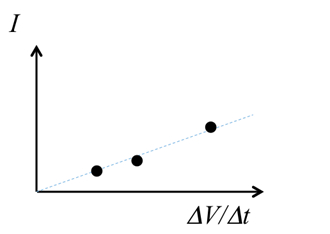
Figure 7: An exemplary linear plot between current and voltage ramp rate.
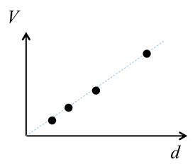
Figure 8: An exemplary linear plot between inter-plate voltage and distance.
Applications and Summary
In this experiment, the charging of a capacitor was demonstrated, where the current is the product of the capacitance and the rate of change of voltage. By observing how the voltage varies given a fixed charge, we have demonstrated how the capacitance of a parallel plate capacitor varies with the separation and with the medium between the plates.
The capacitance meter can also be used to directly measure the capacitance, and determine the total capacitance for capacitors connected in parallel or in series.
Capacitors are commonly used in many circuit applications. They can be used to store charges and energy. They are essential for electrical signal processing. For example, taking the derivative of an electrical signal, so called the "differentiator", as the capacitor current, is directly proportional to the derivative of a time dependent voltage applied to the capacitor. They are also used in filters (the conduction between the two conductors making up a capacitor generally increases at higher frequency although it is very low at low frequency).
The author of the experiment acknowledges the assistance of Gary Hudson for material preparation and Chuanhsun Li for demonstrating the steps in the video.
Transcrição
A capacitor is essential in circuits because it resists changes in voltage by storing equal and opposite charges on its conductive terminals and then supplying energy when the voltage supply drops.
A capacitor is composed of two conductive terminals, such as the two plates in a “parallel plate capacitor”, separated by an insulating material or gap. When voltage is applied across a capacitor, it draws current. This causes electrons to accumulate on one plate while they are repelled on the other, thus storing equal and opposite charges on the two plates.
The ability of the component to store charge is called capacitance, and is measured in units called Farads.
This video uses a parallel plate capacitor to illustrate the concept of capacitance and its dependence on physical factors and network configuration.
When a power source is applied to a circuit, the capacitor draws “charging current” until its conductors are fully charged. The amount of charge ‘Q’ a capacitor can store depends on the capacitance ‘C’ of the component, and the magnitude of the supplied voltage ‘V’.
When the voltage drops, charge from the capacitor’s conductors flows to the circuit, generating current until the stored charge is depleted, thus stabilizing voltage fluctuation. Current is the rate of change in the amount of charge. Combining this with the previous equation, we can say that the current flow out of the capacitor is capacitance times the rate of change in voltage.
The value of C is constant for a given capacitor, and can be obtained by using this equation, which shows that C is directly proportional to A — the plate surface area, d — the gap distance, and epsilon — the dielectric constant or “permittivity” of the insulating material between the plates.
Dielectric constant is a measure of the extent to which the material becomes polarized in an electric field.
Thus, given the relationship between epsilon and C, and C and Q; at a given voltage, higher the permittivity, higher will be the capacitor’s charge storage capacity.
Vacuum has a dielectric constant of 8.85×10⁻¹² Farads per meter, denoted ε0. Other media generally have greater permittivity values, which are scaled to ε0 and termed the “relative” permittivity of the medium. For example, the relative permittivity of air is approximately one, polymers range from 2 to 4, and distilled water is 80.
Now that physical properties effecting capacitance have been explained, let’s take a look at how to measure capacitance in individual or networked capacitive elements.
To start, gather the following materials: a commercial capacitor with capacitance close to 470 micro farad, a programmable voltage source, and an amp-meter or multi-meter that can measure current.
Next, with the voltage source set to 0 V, connect its positive terminal to the amp-meter. Then connect the other port of the amp-meter to the capacitor, using cables with clamps or banana plugs. This enables the measurement of output current from the capacitor. Following that connect the negative port of the voltage source to the other terminal of the capacitor.
Then, switch the voltage source from 0 to 1 V and observe the transient current reading on the amp-meter. Next adjust the voltage back to 0 before increasing to 2 V, 5 V and finally 10 V. For each target voltage allow one second of rest at 0 V between changes to different target voltages. Observe the transient current as the voltage changes.
As predicted by the equation the transient current is expected to be larger for a larger target voltage.
Lastly, program the voltage source to generate a voltage ramp from 0 V to 10V over 5 seconds, and record the “steady state” amp-meter reading mid-ramp. Next, repeat for ramp times of 10 s, 20 s, and 30 s.
Now obtain a parallel plate capacitor with adjustable separation between the plates, and use a 300V battery as the voltage source. Replace the amp-meter with a 1 mega-ohm resistor. This resistor provides an extra protection limiting the current flow in the circuit.
Second, connect a high-impedance voltmeter, or electrometer, between the two plates in order to measure the voltage difference.
Next, connect the battery to the capacitor, and wait until the electrometer also reaches the steady state of 300 V, indicating the capacitor is fully charged. Then quickly disconnect the battery from the plates. The electrometer should still read 300 V.
Repeat the measurement after decreasing the distance between the plates to 15, 10, and 5 mm.
Finally, with a capacitor plate distance of 20 mm, insert a plastic slab between the two plates and observe what happens to the electrometer voltage reading.
For the commercial capacitor, the plot of measured current versus voltage ramp rate reveals a linear relationship between the two parameters.
This complies with the relationship predicated by this equation, which we derived earlier in the video. As per the equation, the slope of the line is equal to the capacitance.
For the parallel plate capacitor with fixed charge, the plot of voltage between the plates versus distance between the plates is linear. This again supports the theoretical relationships. We know that capacitance and plate distance are inversely proportional. We also know that when conductor charge is fixed, capacitance and voltage are also inversely proportional. Combining these two equations reveals that voltage and plate distance are directly proportional to each other when the charge is fixed.
This equation also predicts that with a fixed charge, the larger dielectric constant of the gap medium, the lower would be the voltage between the plates. This was confirmed when the air in the gap was replaced by plastic and we saw a drop in the voltmeter reading.
Capacitors are used in a large variety of engineering and scientific applications to store charge and selectively discharge electricity.
Capacitors are essential for electrical signal processing. For example, biologists used a two-choice test to evaluate how mice recognize and respond to different ultrasonic vocalizations. First, sound files are recorded from live mice and trimmed using high pass filters to select for frequency.
High-pass filter circuits use capacitors to block low frequency oscillations, as the conduction between capacitor plates generally increases at higher frequencies and decreases at low frequencies. Then, variable frequency sounds are simultaneously played in two separate locations, allowing mice to migrate towards the preferred vocalization.
While mains supplies are AC with fluctuating current, many electronic devices, such as computers, require DC power. Capacitors are used within AC power adapters to filter electrical signals and stabilize the DC supply, providing a smooth, uninterrupted source.
You’ve just watched JoVE’s introduction to capacitors. You should now understand the concept of capacitance, how to measure this physical parameter, and how properties like plate-to-plate distance or gap material effect the capacitance value. As always, thanks for watching!